exhaust FIAT 500 1966 1.G Workshop Manual
[x] Cancel search | Manufacturer: FIAT, Model Year: 1966, Model line: 500, Model: FIAT 500 1966 1.GPages: 128, PDF Size: 9.01 MB
Page 2 of 128
CHAPTER 1
THE ENGINE
1 :1
1 :2
1 :3
1 :4
1 :5
1 :6
1 :7
1 :8
1:9
1 :10
1 :11Description
Engine removal (sedan—all versions)
Engine removal (station wagon)
Engine disassembly (sedan—all versions)
Engine disassembly (station wagon)
Cylinder head removal, servicing and
replacement
Timing gear overhaul
Crankcase and cylinders
Piston assembly
Connecting rods
Crankshaft and main bearings
1 :1 Description
The 'New 500' two-cylinder aircooled engine operates
on the four-stroke 'Otto Cycle' and is fitted directly to
the transmission unit which incorporates the rear drive
assembly as shown in FIG 1 :1 and FIG 1 :2.
With the power unit fitted at the rear several advantages
are obtained including better load distribution to the
wheels when the vehicle is loaded, elimination of propeller
shaft reducing the size of centre tunnel and better use of
available space.
The cylinder block comprises t w o cast iron cylinder
barrels w i t h cooling fins. The bottom of the cylinders fit
into machined seats in the aluminium crankcase.
The aluminium crankcase carries eight studs on which
are located the t w o cylinder barrels w i t h the aluminium
cylinder head on the top.
A two bush crankshaft of special cast iron is fitted into
the lower half of the crankcase. The crankshaft is
F5009 provided with a counterweight and is hollow to allow for
lubrication.
The steel connecting rods have thin wall bearing halves
on the big-end, and bronze bushes in the small-end. The
offset piston pin is of steel and retained in the piston by
two circlips.
Light alloy pistons are used and are of the taper-oval-
shaped type with a maximum diameter at the base of the
skirt, along an axis perpendicular to the piston pin. Pistons
are fitted with four rings as follows, one compression at
the top, two standard oil scraper rings and one side slotted
oil scraper ring.
The one-piece aluminium cylinder head is finned to
provide a larger cooling surface and carries the inlet and
exhaust manifolds.
The inlet passages merge into a single centralized
flange onto which is mounted the carburetter. The exhaust
passages run almost parallel to the axis of the engine. 1 :12
1 :13
1 :14
1 :15
1 :16
1 :17
1 :18
1 :19
1 :20
1 :21
1 :22Flywheel and starter ring gear
The oil pump
Lubrication, oil filter, relief valve
Valve timing
Valve stem to rocker clearance
Engine assembly (sedan—all versions)
Engine assembly (station wagon)
Power plant mounting
Adjustment of generator and fan belt drive
Modifications
Fault diagnosis
Page 7 of 128
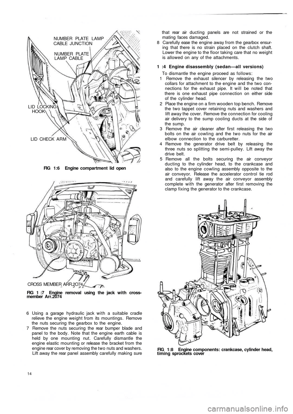
LID CHECK A R M
FIG 1:6 Engine compartment lid open LID LOCKING
HOOK
NUMBER PLATE
LAMP CABLE NUMBER PLATE LAMP
CABLE JUNCTION
CROSS MEMBER ARR.2O74.
FIG 1 :7 Engine removal using the jack with cross-
member Arr.2074
6 Using a garage hydraulic jack with a suitable cradle
relieve the engine weight from its mountings. Remove
the nuts securing the gearbox to the engine.
7 Remove the nuts securing the rear bumper blade and
panel to the body. Note that the engine earth cable is
held by one mounting nut. Carefully dismantle the
engine elastic mounting or release the bracket from the
engine rear cover by removing the two nuts and washers.
Lift away t h e rear panel assembly carefully making sure
14
FIG 1 : 8 Engine components: crankcase, cylinder head,
timing sprockets cover To dismantle the engine proceed as follows:
1 Remove the exhaust silencer by releasing the two
collars for attachment to the engine and the two con-
nections for the exhaust pipe. It will be noted that
there is one exhaust pipe connection on either side
of the cylinder head.
2 Place the engine on a firm wooden top bench. Remove
the two tappet cover retaining nuts and washers and
lift away the cover. Remove the connection for cooling
air delivery to the sump cooling ducts at the side of
the sump.
3 Remove the air cleaner after first releasing the two
bolts on the air cowling and the two nuts for the air
elbow connection to the carburetter.
4 Remove the generator drive belt by releasing the
three nuts so splitting the semi-pulley. Lift away the
drive belt.
5 Remove all the bolts securing the air conveyor
ducting to the cylinder head, to the crankcase and
also to the engine cowling assembly opposite to the
air conveyor. Release the accelerator control tie rod
and carefully lift away the air conveyor assembly
complete with the generator after first removing the
clamp fixing the generator to the crankcase. 1 :4 Engine disassembly (sedan—all versions) t h a t rear air ducting panels are not strained or the
mating faces damaged.
8 Carefully ease the engine away from the gearbox ensur-
ing that there is no strain placed on the clutch shaft.
Lower the engine to the floor taking care that no weight
is allowed on any of the attachments.
Page 9 of 128
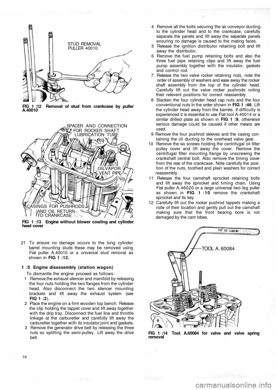
STUD REMOVAL
PULLER 40010
FIG 1 :12 Removal of stud from crankcase by puller
A.40010
FIG 1 :13 Engine without blower cowling and cylinder
head cover.SPACER A N D CONNECTION
FOR ROCKER SHAFT
LUBRICATION TUBE
OILVAPOR
.VENT PIPE
CASINGS FOR PUSHRODS
(AND OIL RETURN
TO CRANKCASE
21 To ensure no damage occurs to the long cylinder
barrel mounting studs these may be removed using
Fiat puller A.40010 or a universal stud removal as
shown in FIG 1 :12.
1 :5 Engine disassembly (station wagon)
To dismantle the engine proceed as follows:
1 Remove the exhaust silencer and manifold by releasing
the four nuts holding the two flanges from the cylinder
head. Also disconnect the two silencer mounting
brackets and lift away the exhaust system (see
FIG 1 : 2).
2 Place the engine on a firm wooden top bench. Release
the clip holding the tappet cover and lift away together
with the drip tray. Disconnect the fuel line and throttle
linkage at the carburetter and carefully lift away the
carburetter together with its insulator joint and gaskets.
3 Remove the generator drive belt by releasing the three
nuts so splitting the semi-pulley. Lift away the drive
belt.
16
FIG 1 :14 Tool A.60084 for valve and valve springremoval
TOOL A . 60084
4 Remove all the bolts securing the air conveyor ducting
to the cylinder head and to the crankcase, carefully
separate the panels and lift away the separate panels
ensuring no damage is caused to the mating faces.
5 Release the ignition distributor retaining bolt and lift
away the distributor.
6 Remove the fuel pump retaining bolts and also the
three fuel pipe retaining clips and lift away the fuel
pump assembly together with the insulator, gaskets
and control rod.
7 Release the t w o valve rocker retaining nuts, note the
order of assembly of washers and ease away the rocker
shaft assembly from the top of the cylinder head.
Carefully lift out the valve rocker pushrods noting
their relevent positions for correct reassembly.
8 Slacken the four cylinder head cap nuts and the four
conventional nuts in the order shown in FIG 1 :46. Lift
the cylinder head away from the barrels. If difficulty is
experienced it is essential to use Fiat tool A.40014 or a
similar drilled plate as shown in FIG 1 :9, otherwise
serious damage could be caused if other means are
used.
9 Remove the four pushrod sleeves and the casing con-
taining the oil ducting to the overhead valve gear.
10 Remove the six screws holding the centrifugal oil filter
pulley cover and lift away the cover. Remove the
centrifugal filter mounting flange by unscrewing the
crankshaft central bolt. Also remove the timing cover
f r o m t h e rear of t h e crankcase. Note carefully the posi-
tion of the nuts, toothed and plain washers for correct
reassembly.
11 Release the four camshaft sprocket retaining bolts
and lift away the sprocket and timing chain. Using
Fiat puller A.46020 or a large universal two-leg puller
as shown in FIG 1 : 1 0 remove the crankshaft
sprocket and its key
12 Carefully lift out the rocker pushrod tappets making a
note of their location and gently pull out the camshaft
making sure that the front bearing bore is not
damaged by the cam lobes.
Page 11 of 128
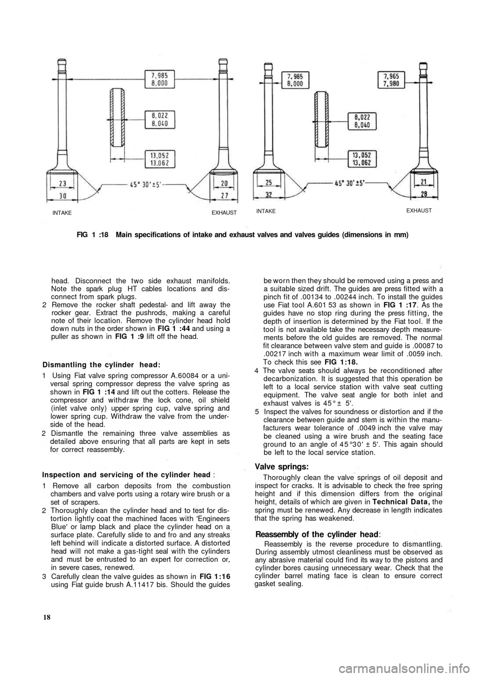
INTAKEEXHAUSTINTAKEEXHAUST
FIG 1 :18 Main specifications of intake and exhaust valves and valves guides (dimensions in mm)
head. Disconnect the t w o side exhaust manifolds.
Note the spark plug HT cables locations and dis-
connect from spark plugs.
2 Remove the rocker shaft pedestal- and lift away the
rocker gear. Extract the pushrods, making a careful
note of their location. Remove the cylinder head hold
down nuts in the order shown in FIG 1 :44 and using a
puller as shown in FIG 1 :9 lift off the head.
Dismantling the cylinder head:
1 Using Fiat valve spring compressor A.60084 or a uni-
versal spring compressor depress the valve spring as
shown in FIG 1 :14 and lift out the cotters. Release t h e
compressor and withdraw the lock cone, oil shield
(inlet valve only) upper spring cup, valve spring and
lower spring cup. Withdraw the valve from the under-
side of the head.
2 Dismantle the remaining three valve assemblies as
detailed above ensuring that all parts are kept in sets
for correct reassembly.
Inspection and servicing of the cylinder head :
1 Remove all carbon deposits from the combustion
chambers and valve ports using a rotary wire brush or a
set of scrapers.
2 Thoroughly clean the cylinder head and to test for dis-
tortion lightly coat the machined faces with 'Engineers
Blue' or lamp
black and place the cylinder head on a
surface plate. Carefully slide to and fro and any streaks
left behind will indicate a distorted surface. A distorted
head will not make a gas-tight seal with the cylinders
and must be entrusted to an expert for correction or,
in severe cases, renewed.
3 Carefully clean the valve guides as shown in FIG 1:16
using Fiat guide brush A.11417 bis. Should the guides
18Reassembly is the reverse procedure to dismantling.
During assembly utmost cleanliness must be observed as
any abrasive material could find its way to the pistons and
cylinder bores causing unnecessary wear. Check that the
cylinder barrel mating face is clean to ensure correct
gasket sealing.Reassembly of t h e cylinder head:
be worn then they should be removed using a press and
a suitable sized drift. The guides are press fitted with a
pinch fit of .00134 to .00244 inch. To install the guides
use Fiat tool A.601 53 as shown in FIG 1 :17. As the
guides have no stop ring during the press fitting, the
depth of insertion is determined by the Fiat tool. If the
tool is not available take the necessary depth measure-
ments before the old guides are removed. The normal
fit clearance between valve stem and guide is .00087 to
.00217 inch with a maximum wear limit of .0059 inch.
To check this see FIG 1:18.
4 The valve seats should always be reconditioned after
decarbonization. It is suggested that this operation be
left to a local service station with valve seat cutting
equipment. The valve seat angle for both inlet and
exhaust valves is 4 5 ° ± 5'.
5 Inspect the valves for soundness or distortion and if the
clearance between guide and stem is within the manu-
facturers wear tolerance of .0049 inch the valve may
be cleaned using a wire brush and the seating face
ground to an angle of 45°30' ± 5'. This again should
be left to the local service station.
Valve springs:
Thoroughly clean the valve springs of oil deposit and
inspect for cracks. It is advisable to check the free spring
height and if this dimension differs from the original
height, details of which are given in Technical Data, the
spring must be renewed. Any decrease in length indicates
that the spring has weakened.
Page 12 of 128
Cylinder head installation:
To refit the cylinder head proceed as follows:
Place a new cylinder head joint on the cleaned faces of
the cylinder barrels. Insert the rocker pushrod and
lubrication pipe sleeves together with the relevant
gaskets and rings.
Fit the washers and nuts to the studs and tighten to
fingertight.
Tighten the nuts in the order shown in FIG 1 :44 and
FIG 1 :46 to a torque wrench setting of 18.1 Ibft. Reset
the torque wrench to a new setting of 23.9 Ibft and
tighten the nuts once more in the recommended order.
Replace the pushrods in the correct order.
Refit the rocker shaft ensuring correct location of the
lubrication tube to the rocker shaft and replace the
plain and lockwashers. Tighten the nuts to a torque
wrench setting of 15.2 Ibft. Reset the tappet to rocker
clearance adjustment.
Connect the t w o exhaust side manifolds to the cylinder
head. Using new gasket refit the spark plugs and HT
cables. Replace the rocker cover fitted with a new cork
gasket and blower conveyor to the cylinder head
securing screws. Refit the carburetter and reconnect its
fuel line and controls. Refit the air cleaner and elbow
and connect the rocker cover breather pipe (if fitted).
1
2
3
4
5
1 :7 Timing gear overhaul
Camshaft:
The cast iron camshaft is located in the crankcase and is
supported at either end in sets machined directly in the
crankcase. No bushes are used. The camshaft is driven by
a chain from the crankshaft at half engine speed and
operates the overhead valves through tappets, pushrods
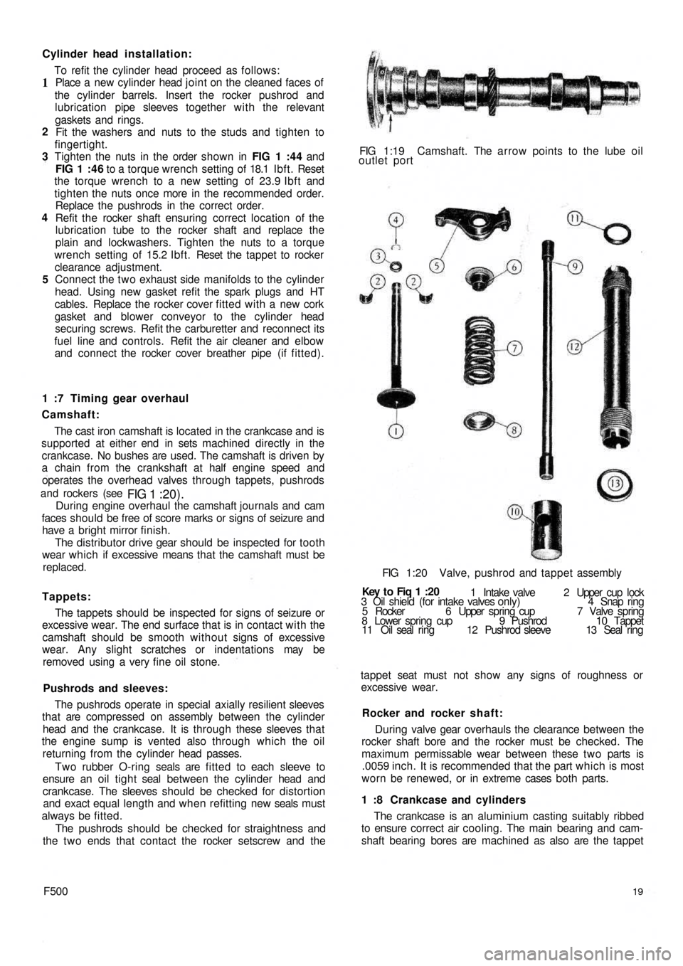
and rockers (see
FIG 1 :20).During engine overhaul the camshaft journals and cam
faces should be free of score marks or signs of seizure and
have a bright mirror finish.
The distributor drive gear should be inspected for tooth
wear which if excessive means that the camshaft must be
replaced.
Tappets:
The tappets should be inspected for signs of seizure or
excessive wear. The end surface that is in contact with the
camshaft should be smooth without signs of excessive
wear. Any slight scratches or indentations may be
removed using a very fine oil stone.
Pushrods and sleeves:
The pushrods operate in special axially resilient sleeves
that are compressed on assembly between the cylinder
head and the crankcase. It is through these sleeves that
the engine sump is vented also through which the oil
returning from the cylinder head passes.
Two rubber O-ring seals are fitted to each sleeve to
ensure an oil t i g h t seal between the cylinder head and
crankcase. The sleeves should be checked for distortion
and exact equal length and when refitting new seals must
always be fitted.
The pushrods should be checked for straightness and
the t w o ends that contact the rocker setscrew and the
F50019
The crankcase is an aluminium casting suitably ribbed
to ensure correct air cooling. The main bearing and cam-
shaft bearing bores are machined as also are the tappet 1 :8 Crankcase and cylinders During valve gear overhauls the clearance between the
rocker shaft bore and the rocker must be checked. The
maximum permissable wear between these t w o parts is
.0059 inch. It is recommended that the part which is most
worn be renewed, or in extreme cases both parts. Rocker and rocker shaft: tappet seat must not show any signs of roughness or
excessive wear. 3 Oil shield (for intake valves only) 4 Snap ring
5 Rocker 6 Upper spring cup 7 Valve spring
8 Lower spring cup 9 Pushrod 10 Tappet
11 Oil seal ring 12 Pushrod sleeve 13 Seal ring 1 Intake valve 2 Upper cup lock Key t o Fiq
1 :20 FIG 1:20 Valve, pushrod and tappet assembly FIG 1:19 Camshaft. The arrow points to the lube oil
outlet port
Page 21 of 128
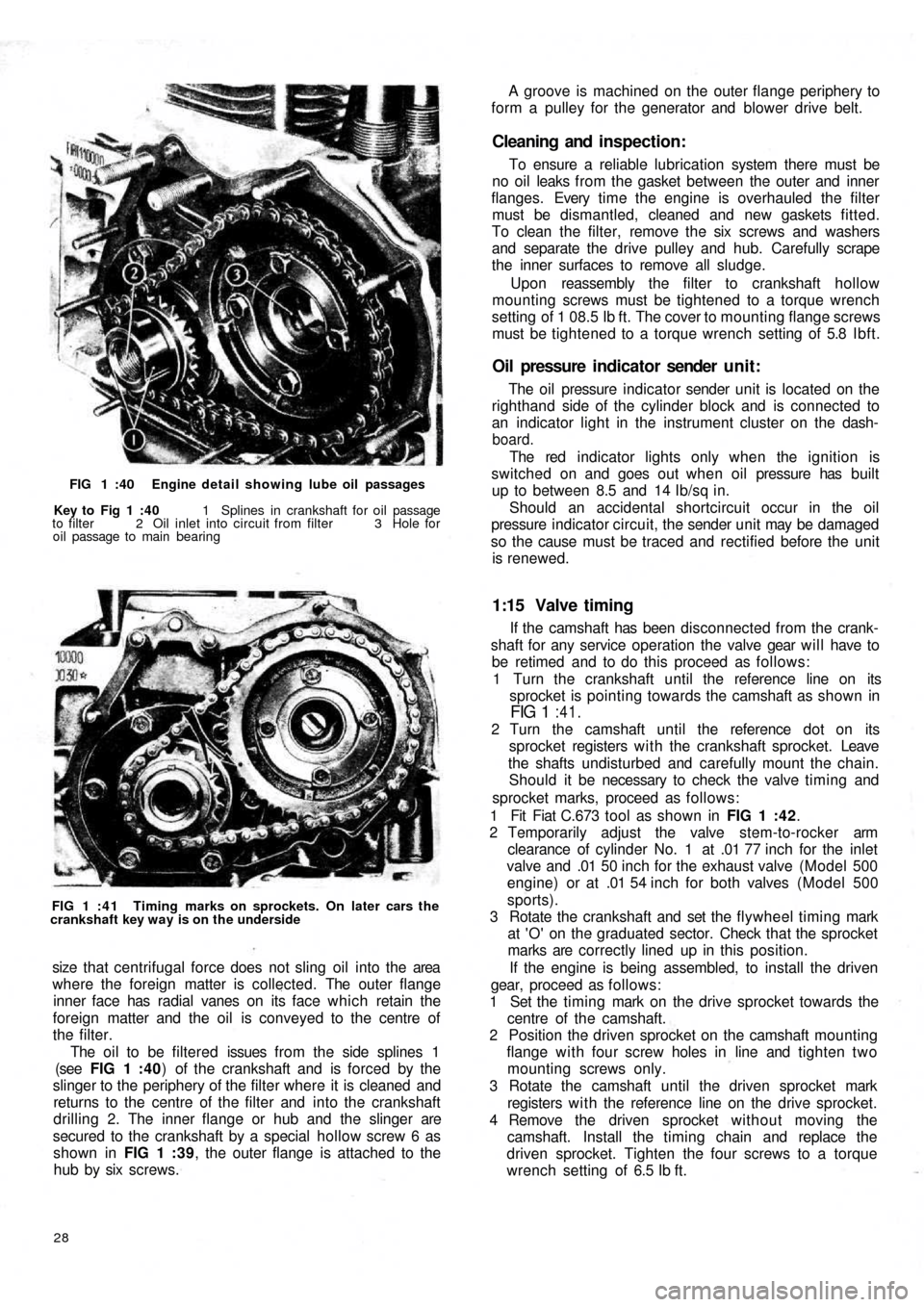
FIG 1 :40 Engine detail showing lube oil passages
Key to Fig 1 :40 1 Splines in crankshaft for oil passage
to filter 2 Oil inlet into circuit from filter 3 Hole for
oil passage to main bearing
FIG 1 : 4 1 Timing marks on sprockets. On later cars the
crankshaft key way is on the underside
size that centrifugal force does not sling oil into the area
where the foreign matter is collected. The outer flange
inner face has radial vanes on its face which retain the
foreign matter and the oil is conveyed to the centre of
the filter.
The oil to be filtered issues from the side splines 1
(see FIG 1 :40) of the crankshaft and is forced by the
slinger to the periphery of the filter where it is cleaned and
returns to the centre of the filter and into the crankshaft
drilling 2. The inner flange or hub and the slinger are
secured to the crankshaft by a special hollow screw 6 as
shown in FIG 1 :39, the outer flange is attached to the
hub by six screws.
28
If the camshaft has been disconnected from the crank-
shaft for any service operation the valve gear will have to
be retimed and to do this proceed as follows:
1 Turn the crankshaft until the reference line on its
sprocket is pointing towards the camshaft as shown in
FIG 1 :41.
2 Turn the camshaft until the reference dot on its
sprocket registers w i t h the crankshaft sprocket. Leave
the shafts undisturbed and carefully mount the chain.
Should it be necessary to check the valve timing and
sprocket marks, proceed as follows:
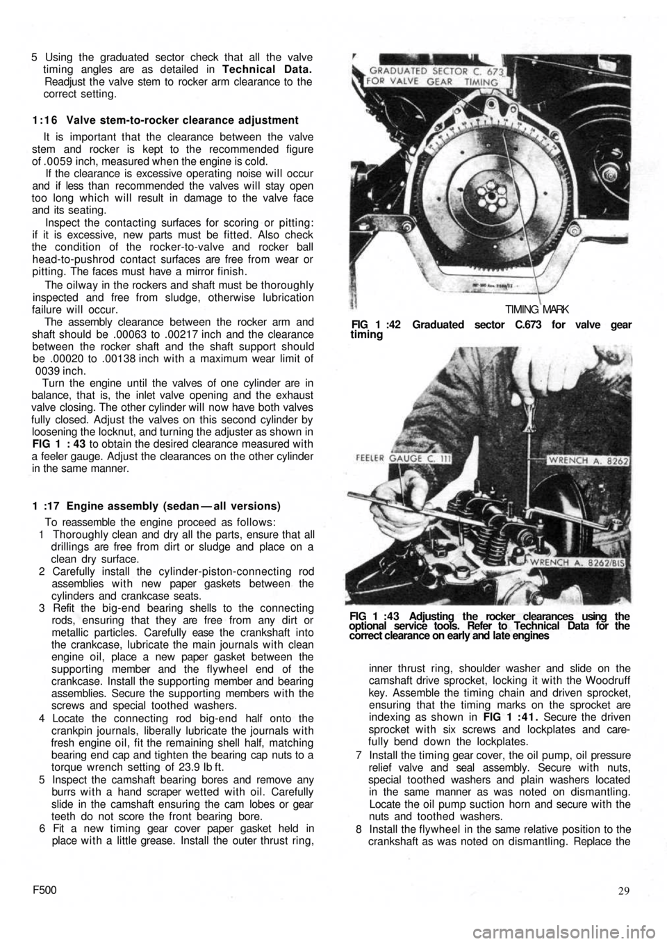
1 Fit Fiat C.673 tool as shown in FIG 1 :42.
2 Temporarily adjust the valve stem-to-rocker arm
clearance of cylinder No. 1 at .01 77 inch for the inlet
valve and .01 50 inch for the exhaust valve (Model 500
engine) or at .01 54 inch for both valves (Model 500
sports).
3 Rotate the crankshaft and set the flywheel timing mark
at 'O' on the graduated sector. Check that the sprocket
marks are correctly lined up in this position.
If the engine is being assembled, to install the driven
gear, proceed as follows:
1 Set the timing mark on the drive sprocket towards the
centre of the camshaft.
2 Position the driven sprocket on the camshaft mounting
flange with four screw holes in line and tighten two
mounting screws only.
3 Rotate the camshaft until the driven sprocket mark
registers w i t h the reference line on the drive sprocket.
4 Remove the driven sprocket without moving the
camshaft. Install the timing chain and replace the
driven sprocket. Tighten the four screws to a torque
wrench setting of 6.5 Ib ft.
1:15 Valve timing
The oil pressure indicator sender unit is located on the
righthand side of the cylinder block and is connected to
an indicator light in the instrument cluster on the dash-
board.
The red indicator lights only when the ignition is
switched on and goes out when o i l pressure has built
up to between 8.5 and 14 Ib/sq in.
Should an accidental shortcircuit occur in the oil
pressure indicator circuit, the sender unit may be damaged
so the cause must be traced and rectified before the unit
is renewed.
Oil pressure indicator sender unit:
To ensure a reliable lubrication system there must be
no oil leaks from the gasket between the outer and inner
flanges. Every t i m e t h e engine is overhauled the filter
must be dismantled, cleaned and new gaskets fitted.
To clean the filter, remove the six screws and washers
and separate the drive pulley and hub. Carefully scrape
the inner surfaces to remove all sludge.
Upon reassembly the filter to crankshaft hollow
mounting screws must be tightened to a torque wrench
setting of 1 08.5 Ib ft. The cover to mounting flange screws
must be tightened to a torque wrench setting of 5.8 Ibft.
Cleaning and inspection:
A groove is machined on the outer flange periphery to
form a pulley for the generator and blower drive belt.
Page 22 of 128
5 Using the graduated sector check that all the valve
timing angles are as detailed in Technical Data.
Readjust the valve stem to rocker arm clearance to the
correct setting.
1:16 Valve stem-to-rocker clearance adjustment
It is important that the clearance between the valve
stem and rocker is kept to the recommended figure
of .0059 inch, measured when the engine is cold.
If the clearance is excessive operating noise will occur
and if less than recommended the valves will stay open
too long which will result in damage to the valve face
and its seating.
Inspect the contacting surfaces for scoring or pitting:
if it is excessive, new parts must be fitted. Also check
the condition of the rocker-to-valve and rocker ball
head-to-pushrod contact surfaces are free from wear or
pitting. The faces must have a mirror finish.
The oilway in the rockers and shaft must be thoroughly
inspected and free from sludge, otherwise lubrication
failure will occur.
The assembly clearance between the rocker arm and
shaft should be .00063 to .00217 inch and the clearance
between the rocker shaft and the shaft support should
be .00020 to .00138 inch with a maximum wear limit of
0039 inch.
Turn the engine until the valves of one cylinder are in
balance, that is, the inlet valve opening and the exhaust
valve closing. The other cylinder will now have both valves
fully closed. Adjust the valves on this second cylinder by
loosening the locknut, and turning the
adjuster as shown in
FIG 1 : 43 to obtain the desired clearance measured with
a feeler gauge. Adjust the clearances on the other cylinder
in the same manner.
1 :17 Engine assembly (sedan — all versions)
To reassemble the engine proceed as follows:
1 Thoroughly clean and dry all the parts, ensure that all
drillings are free from dirt or sludge and place on a
clean dry surface.
2 Carefully install the cylinder-piston-connecting rod
assemblies w i t h new paper gaskets between the
cylinders and crankcase seats.
3 Refit the big-end bearing shells to the connecting
rods, ensuring that they are free from any dirt or
metallic particles. Carefully ease t h e crankshaft into
the crankcase, lubricate the main journals with clean
engine oil, place a new paper gasket between the
supporting member and the flywheel end of the
crankcase. Install the supporting member and bearing
assemblies. Secure the supporting members with the
screws and special toothed washers.
4 Locate the connecting rod big-end half onto the
crankpin journals, liberally lubricate the journals with
fresh engine oil, fit the remaining shell half, matching
bearing end cap and tighten the bearing cap nuts to a
torque wrench setting of 23.9 Ib ft.
5 Inspect the camshaft bearing bores and remove any
burrs w i t h a hand scraper wetted with oil. Carefully
slide in the camshaft ensuring the cam lobes or gear
teeth do not score the front bearing bore.
6 Fit a new timing gear cover paper gasket held in
place w i t h a little grease. Install the outer thrust ring,
F50029 inner thrust ring, shoulder washer and slide on the
camshaft drive sprocket, locking it with the Woodruff
key. Assemble the timing chain and driven sprocket,
ensuring that the timing marks on the sprocket are
indexing as shown in FIG 1 :41. Secure the driven
sprocket with six screws and lockplates and care-
fully bend down the lockplates.
7 Install the timing gear cover, the oil pump, oil pressure
relief valve and seal assembly. Secure w i t h nuts,
special toothed washers and plain washers located
in the same manner as was noted on dismantling.
Locate the oil pump suction horn and secure with the
nuts and toothed washers.
8 Install the flywheel in the same relative position to the
crankshaft as was noted on dismantling. Replace the FIG 1 : 4 3 Adjusting the rocker clearances using the
optional service tools. Refer to Technical Data for the
correct clearance on early and late engines FIG 1 :42 Graduated sector C.673 for valve gear
timing
TIMING MARK
Page 23 of 128
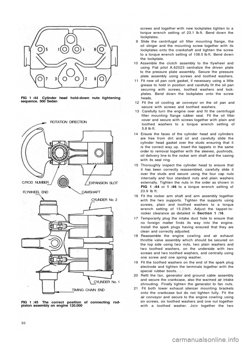
FIG 1 :44 Cylinder head h o ld-down nuts tightening
sequence. 500 Sedan
TIMING CHAIN ENDCYLINDER No. 1 CYLINDER No. 2 FLYWHEEL END
CAMSHAFT
EXPANSION SLOT C/ROD NUMBERROTATION DIRECTION
FIG 1 :45 The correct position of connecting rod-
piston assembly on engine 120.000
30
screws and together with new lockplates tighten to a
torque wrench setting of 23.1 Ib ft. Bend down the
lockplates.
9 Slide the centrifugal oil filter mounting flange, the
oil slinger and the mounting screw together with its
lockplates onto the crankshaft and tighten the screw
to a torque wrench setting of 108.5 Ib ft. Bend down
the lockplate.
10 Assemble the clutch assembly to the flywheel and
using Fiat pilot A.62023 centralize the driven plate
to the pressure plate assembly. Secure the pressure
plate assembly using screws and toothed washers.
11 Fit new oil pan cork gasket, if necessary using a little
grease to hold in position and carefully fit the oil pan
securing with screws, toothed washers and lock-
plates. Bend down the lockplates onto the screw
heads.
12 Fit the oil cooling air conveyor on the oil pan and
secure with screws and toothed washers.
13 Carefully turn the engine over and fit the centrifugal
filter mounting flange rubber seal. Fit the oil filter
cover and secure with screws together with plain and
toothed washers to a torque wrench setting of
5.8
Ib ft.
14 Ensure t h e faces of the cylinder head and cylinders
are free from dirt and oil and carefully slide the
cylinder head gasket over the studs ensuring that it
is the correct way up. Insert the tappets in the same
order to removal together with the sleeves, pushrods,
oil delivery line to the rocker arm shaft and the casing
with its seal ring.
15 Thoroughly inspect the cylinder head to ensure that
it has been correctly reassembled, carefully slide it
over the studs and secure using the four cap nuts
internally and four standard nuts and plain washers
externally. Tighten the nuts in the order as shown in
FIG 1 :44 or 1 :46 to a torque wrench setting of
23.9 Ib ft.
16 Fit the rocker arm shaft and arm assembly together
with the two supports. Tighten the supports using
screws, plain and toothed washers to a torque
wrench setting of 15.2Ibft. Adjust the tappet-to-
rocker clearance as detailed in Section 1 :16.
17 Temporarily plug the intake duct hole to ensure that
no foreign matter finds its way into the engine.
Install the spark plugs having ensured that they are
clean and correctly adjusted.
18 Reassemble the engine cowling and air
exhaust
throttle valve assembly which should be secured on
the top side using t w o nuts, t w o plain washers and
two toothed washers, on the underside with two
screws and t w o toothed washers, and centrally using
one screw and one spring washer.
19 Fit the toothed washers on the end of the spark plug
electrode and tighten the terminals together with the
special rubber boots.
20 Refit the fan, generator and ground cable assembly
and secure the crankcase, also the warmed air intake
shrouding. Finally tighten the generator to fan nuts.
21 Fit both lower exhaust silencer mounting brackets
onto the crankcase but do not tighten fully. Fit the
air conveyor and secure to the engine cowling using
six screws, six toothed washers and one nut together
with a toothed washer. Join together the t w o
Page 24 of 128
sections of the air conveyor securing with seven
screws, seven toothed washers and five nuts.
22 Slide the fuel pump control rod into its seating,
assemble the insulator between oil wetted graphite
gaskets and fit the pump to the crankcase using nuts
and toothed washers.
23 Fit the air conveyor cover complete with the accelera-
tor control relay lever and rod. Secure using eight
mounting screws, eight toothed washers, eight plain
washers and eight nuts. Fit the fuel line retaining clip
which is secured by one of the air conveyor upper
screws. Install the generator and fan drive pulley
having first placed four adjusting rings between the
pulley halves and the thrust ring on the outside.
Secure the pulley to generator shaft using three
screws and three toothed washers. Fit the generator
fan drive belt.
24 Refit the carburetter having first positioned the
bakelite heat shield between the t w o oil moistened
graphite gaskets. Secure the carburetter using t w o
copper washers and t w o self-locking nuts. Fit the
exhaust silencer and secure to the exhaust manifolds
with nuts and spring washers. Place the t w o graphite
gaskets between the manifold joints. Fit both exhaust
silencer upper mounting brackets and secure them
on the top side to the brackets already in place w i t h
nuts and toothed washers on the bottom side w i t h
screws and toothed washers.
25 Carefully position the distributor at a 10 deg advance
setting and secure w i t h a
nut, plain washer and
spring washer. Fit the fuel pump to carburetter line
complete w i t h mounting bracket rubber lining and
secure the line with two clamps. If difficulty is
experienced in positioning the fuel line into the pump
or carburetter funnels it is suggested that the line
ends should be heated in hot water and thoroughly
dried before installing.
26 Install the air cleaner elbow and rubber hose assembly
on the top of the carburetter using a graphite gasket
in between and secure w i t h nuts, plain washers and
spring washers. Carefully position the air cleaner, line
and hose assembly and connect it to the elbow.
Secure the cleaner to air conveyor cover using screws
and toothed washers.
27 Fit the spark plug cables complete with the rubber
grommet for cable mounting bracket on engine
cowling and connect the cables to the distributor
and spark plugs. Fit the oil pressure gauge sender
unit together w i t h its sealing washer.
28 Install the cylinder head cover and oil breather pipe
assembly w i t h a cork gasket inserted between.
Secure w i t h self-locking nuts and fibre washers.
Connect the accelerator control relay lever rod to the
carburetter and secure with the clip.
29 Fill the oil pan with the correct grade and quantity of
oil, insert the dipstick and the engine is ready for
refitting.
1:18 Engine assembly (station wagon)
Reassembly of this engine is straightforward as it is
the reverse procedure to dismantling. It is recommended
that Sections 1 :5 and 1 :17 are studied as the assembly
technique is similar for both the horizontal and vertical
F50031 cylinder engines. The following points should however
be noted:
1 Refer to FIG 1 :45 for the correct positioning of the
connecting rod-piston assembly on the 120.000
engine.
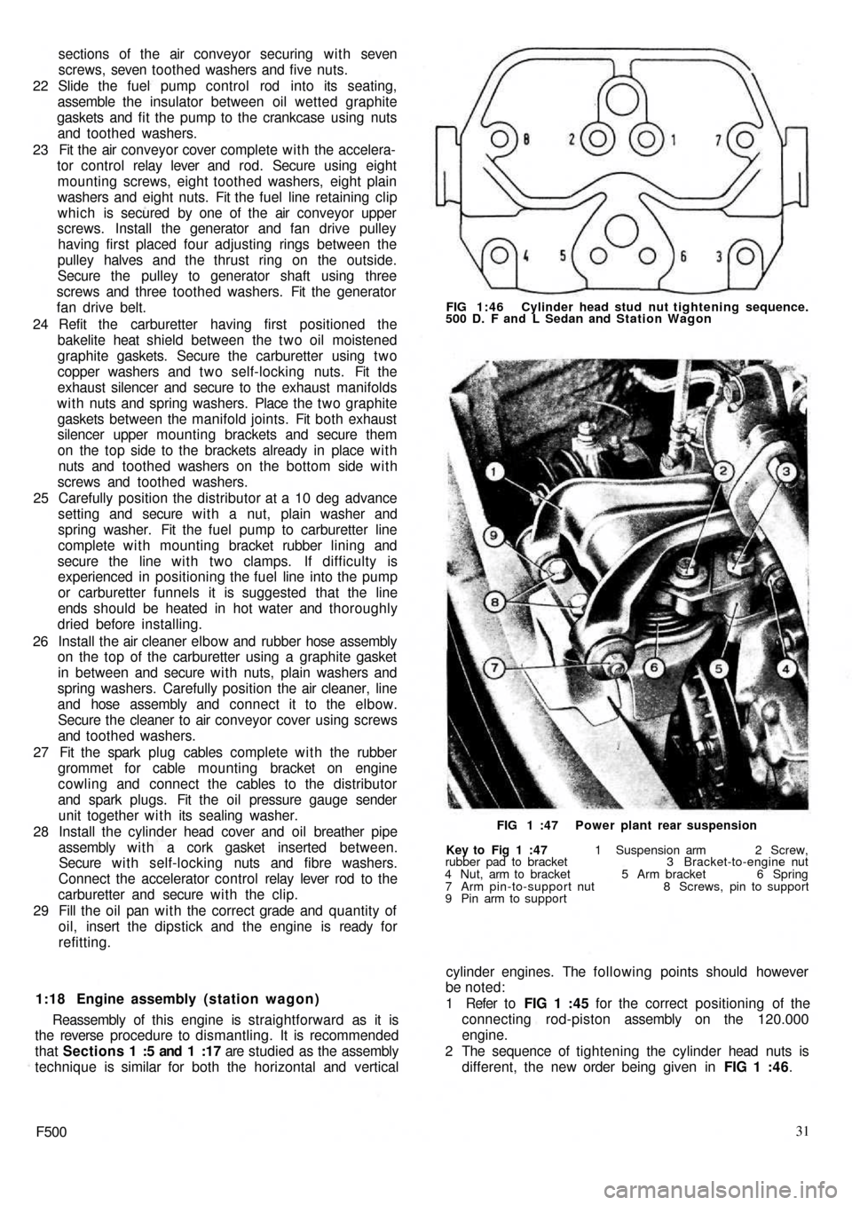
2 The sequence of tightening the cylinder head nuts is
different, the new order being given in FIG 1 :46.
Key to Fig 1 :47 1 Suspension arm 2 Screw,
rubber pad to bracket 3 Bracket-to-engine nut
4 Nut, arm to bracket 5 Arm bracket 6 Spring
7 Arm pin-to-support nut 8 Screws, pin to support
9 Pin arm to supportFIG 1 :47 Power plant rear suspension FIG 1:46 Cylinder head stud nut tightening sequence.
500 D. F and L Sedan and Station Wagon
Page 26 of 128
4 Mixture too weak
5 Water in fuel system
6 Petrol tank vent blocked
7 Incorrect valve clearance
(c) Engine idles badly
1 Check 1 and 6 in (b)
2 Air leak at manifold joints
3 Slow-running jet blocked or out of adjustment
4 Air leak in carburetter
5 Over-rich mixture
6 Worn piston rings
7 Worn valve stems or guides
8 Weak exhaust valve springs
(d) Engine misfires
1 Check 1, 2, 3, 4, 5, 8, 10, 13, 14, 1 5, 16, 17 in (a);
2, 3, 4 and 7 in (b)
2 Weak or broken valve springs
(e) Engine overheats
1 Generator and fan drive belt too loose
2 Shutter or thermostat seized in closed position
(f) Compression low
1 Check 14 and 15 in (a), 6 and 7 in (c) and 2 in (d)
2 Worn piston ring grooves
3 Scored or worn cylinder bores
(g) Engine lacks power
1 Check 3, 10, 1 1 , 13, 14, 15, 16 and 17 in (a), 2, 3, 4
and 7 in (b) 6 and 7 in (c) and 2 in (d). Also check (e)
and (f)
2 Leaking joint washers
3 Fouled sparking plugs
4 Automatic centrifugal advance not operating
(h) Burnt valves or seats
1 Check 14 and 15 in (a), 7 in (b) and 2 in (d). Alsocheck (e)
2 Excessive carbon around valve seat and head
(j) Sticking valves
1 Check 2 in (d)
2 Bent valve stem
3 Scored valve stem or guide
4 Incorrect valve clearance
(k) Excessive cylinder wear
1 Check 11 in (a) and see Chapter 4
2 Lack of oil
3 Dirty oil
4 Piston rings gummed up or broken
5 Badly fitting piston rings
6 Connecting rods bent
(l) Excessive oil consumption
1 Check 6 and 7 in (c) and check (k)
2 Ring gaps too wide
3 Oil return holes in piston choked with carbon
4 Scored cylinders
5 Oil level too high
6 External oil leaks
7 Ineffective valve stem oil seals
(m) Crankshaft and connecting rod bearing failure
1 Check 2 in (k)
2 Restricted oilways
3 Worn journals or crank pins
4 Loose bearing caps
5 Extremely low oil pressure
6 Bent connecting rod
(n) High fuel consumption (see Chapter 2)
(o) Engine vibration
1 Loose generator bolts
2 Blower blade assembly out-of-balance
3 Incorrect clearance for rear engine mounting rubber
F50033