check engine light FIAT 500 1967 1.G Workshop Manual
[x] Cancel search | Manufacturer: FIAT, Model Year: 1967, Model line: 500, Model: FIAT 500 1967 1.GPages: 128, PDF Size: 9.01 MB
Page 6 of 128
The interior of the car can be heated by the engine
warmed air being ducted into the front compartment and
controlled by a lever on the heating system tunnel.
Engine ignition is by a battery, ignition coil and distribu-
tor which is driven by a gear on the camshaft. The engine
is started by an electric starter motor which is mounted on
the gearbox casing and is controlled by a lever located
behind the gearchange lever.
The complete power unit is mounted by a spring support
at the centre of the rear b o d y crossmember and by t w o
rubber pads mounted laterally to the gearbox.
1 :2 Engine removal (sedan—all versions)
To remove the engine from the car proceed as follows:
Raise t h e rear of t h e car and place on firmly based
stands placed under suitable brackets on the underside
of the body.
Disconnect the battery positive terminal clamp from the
battery terminal post. Release the clip securing the main
petrol pipe to the tank sender unit and ease t h e pipe
from the unit. Drain the oil from the engine sump into
a suitably sized container.
D i s c o n n e c t t h e rear number plate light wire (see
FIG 1 : 6) . Release t h e engine compartment lid check
strap from its slot and separate the lid from the body by
sliding the hinge apart.
Remove the cables attached to the ignition coil, also
to the generator and the starter motor. Remove the
starter motor control tie rod.
Release the oil pressure
indicator cable, the main petrol pipeline at the pump,
the accelerator and starting device controls.
Remove the t w o hoses of the heating and cooling
system which are the input hose to the blower and the
hose for the car heating system. Release and lift out the
engine apron. Remove the starter motor mounting bolts
and carefully lift away the motor.
Using a garage hydraulic jack with suitable cradle (see
FIG 1 : 7) or a rope sling relieve the engine weight
from its mountings. Remove the nuts securing the
gearbox to the engine and the flywheel protection
apron.
Remove the bolts fixing the elastic support to the cross-
member. Remove the rear crossmember mounting nuts
noting that the engine earth cable is held by one
mounting nut and lift away the crossmember.
Carefully ease t h e engine away from the gearbox
ensuring that there is no strain placed on the clutch
shaft. Lower the engine to the floor taking care that no
weight is allowed on any of the attachments. 1
2
3
4
5
6
7
8
1 :3 Engine removal (station wagon)
To remove the engine from the station wagon proceed
as follows:
1 Raise t h e rear of the vehicle and place on firmly based
stands placed under suitable brackets on the underside
of the body.
2 Disconnect the battery positive terminal clamp from
the battery terminal post. Release the clip securing the
main petrol pipe to the tank sender unit and ease the
pipe from the unit. Drain the oil from the engine sump
into a clean dry container of suitable size.
3 H o l d t h e rear door open and secure using string to stop
it swinging to the closed position. Secure the luggage
compartment floor panel in its upright position.
F50013 4 Remove the cables attached to the ignition coil, also
to the generator and starter motor. Remove the starter
motor control tie rod. Release the o i l pressure indicator
cable, the main petrol pipeline at the pump, the accele-
rator and starting device controls. Disconnect the air
filter housing.
5 Remove the hose connecting the car heating system
to the engine cowling. Disconnect the clip holding the
air pipe to the blower and carefully disconnect the pipe
from the blower cowling. Remove the starter motor
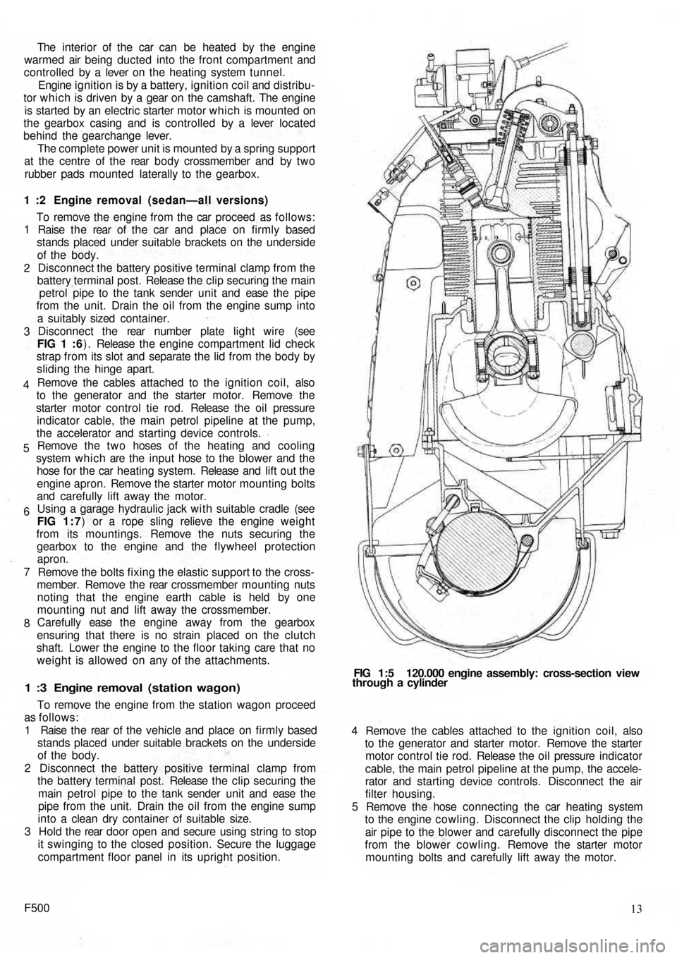
mounting bolts and carefully lift away the motor. FIG 1:5 120.000 engine assembly: cross-section view
through a cylinder
Page 11 of 128
INTAKEEXHAUSTINTAKEEXHAUST
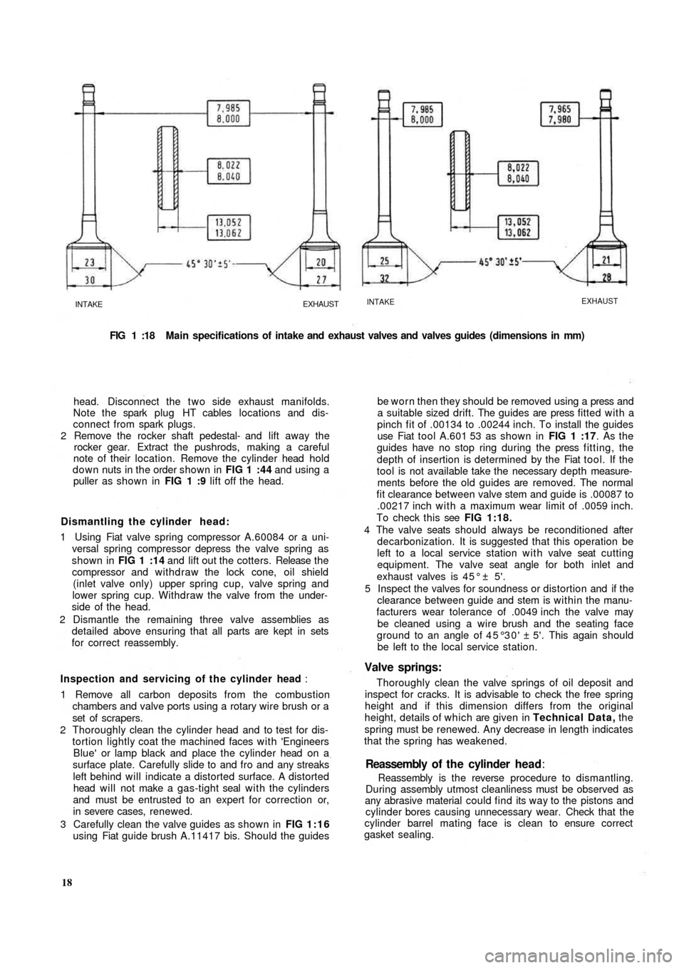
FIG 1 :18 Main specifications of intake and exhaust valves and valves guides (dimensions in mm)
head. Disconnect the t w o side exhaust manifolds.
Note the spark plug HT cables locations and dis-
connect from spark plugs.
2 Remove the rocker shaft pedestal- and lift away the
rocker gear. Extract the pushrods, making a careful
note of their location. Remove the cylinder head hold
down nuts in the order shown in FIG 1 :44 and using a
puller as shown in FIG 1 :9 lift off the head.
Dismantling the cylinder head:
1 Using Fiat valve spring compressor A.60084 or a uni-
versal spring compressor depress the valve spring as
shown in FIG 1 :14 and lift out the cotters. Release t h e
compressor and withdraw the lock cone, oil shield
(inlet valve only) upper spring cup, valve spring and
lower spring cup. Withdraw the valve from the under-
side of the head.
2 Dismantle the remaining three valve assemblies as
detailed above ensuring that all parts are kept in sets
for correct reassembly.
Inspection and servicing of the cylinder head :
1 Remove all carbon deposits from the combustion
chambers and valve ports using a rotary wire brush or a
set of scrapers.
2 Thoroughly clean the cylinder head and to test for dis-
tortion lightly coat the machined faces with 'Engineers
Blue' or lamp
black and place the cylinder head on a
surface plate. Carefully slide to and fro and any streaks
left behind will indicate a distorted surface. A distorted
head will not make a gas-tight seal with the cylinders
and must be entrusted to an expert for correction or,
in severe cases, renewed.
3 Carefully clean the valve guides as shown in FIG 1:16
using Fiat guide brush A.11417 bis. Should the guides
18Reassembly is the reverse procedure to dismantling.
During assembly utmost cleanliness must be observed as
any abrasive material could find its way to the pistons and
cylinder bores causing unnecessary wear. Check that the
cylinder barrel mating face is clean to ensure correct
gasket sealing.Reassembly of t h e cylinder head:
be worn then they should be removed using a press and
a suitable sized drift. The guides are press fitted with a
pinch fit of .00134 to .00244 inch. To install the guides
use Fiat tool A.601 53 as shown in FIG 1 :17. As the
guides have no stop ring during the press fitting, the
depth of insertion is determined by the Fiat tool. If the
tool is not available take the necessary depth measure-
ments before the old guides are removed. The normal
fit clearance between valve stem and guide is .00087 to
.00217 inch with a maximum wear limit of .0059 inch.
To check this see FIG 1:18.
4 The valve seats should always be reconditioned after
decarbonization. It is suggested that this operation be
left to a local service station with valve seat cutting
equipment. The valve seat angle for both inlet and
exhaust valves is 4 5 ° ± 5'.
5 Inspect the valves for soundness or distortion and if the
clearance between guide and stem is within the manu-
facturers wear tolerance of .0049 inch the valve may
be cleaned using a wire brush and the seating face
ground to an angle of 45°30' ± 5'. This again should
be left to the local service station.
Valve springs:
Thoroughly clean the valve springs of oil deposit and
inspect for cracks. It is advisable to check the free spring
height and if this dimension differs from the original
height, details of which are given in Technical Data, the
spring must be renewed. Any decrease in length indicates
that the spring has weakened.
Page 12 of 128
Cylinder head installation:
To refit the cylinder head proceed as follows:
Place a new cylinder head joint on the cleaned faces of
the cylinder barrels. Insert the rocker pushrod and
lubrication pipe sleeves together with the relevant
gaskets and rings.
Fit the washers and nuts to the studs and tighten to
fingertight.
Tighten the nuts in the order shown in FIG 1 :44 and
FIG 1 :46 to a torque wrench setting of 18.1 Ibft. Reset
the torque wrench to a new setting of 23.9 Ibft and
tighten the nuts once more in the recommended order.
Replace the pushrods in the correct order.
Refit the rocker shaft ensuring correct location of the
lubrication tube to the rocker shaft and replace the
plain and lockwashers. Tighten the nuts to a torque
wrench setting of 15.2 Ibft. Reset the tappet to rocker
clearance adjustment.
Connect the t w o exhaust side manifolds to the cylinder
head. Using new gasket refit the spark plugs and HT
cables. Replace the rocker cover fitted with a new cork
gasket and blower conveyor to the cylinder head
securing screws. Refit the carburetter and reconnect its
fuel line and controls. Refit the air cleaner and elbow
and connect the rocker cover breather pipe (if fitted).
1
2
3
4
5
1 :7 Timing gear overhaul
Camshaft:
The cast iron camshaft is located in the crankcase and is
supported at either end in sets machined directly in the
crankcase. No bushes are used. The camshaft is driven by
a chain from the crankshaft at half engine speed and
operates the overhead valves through tappets, pushrods
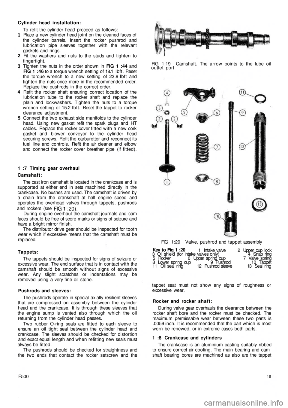
and rockers (see
FIG 1 :20).During engine overhaul the camshaft journals and cam
faces should be free of score marks or signs of seizure and
have a bright mirror finish.
The distributor drive gear should be inspected for tooth
wear which if excessive means that the camshaft must be
replaced.
Tappets:
The tappets should be inspected for signs of seizure or
excessive wear. The end surface that is in contact with the
camshaft should be smooth without signs of excessive
wear. Any slight scratches or indentations may be
removed using a very fine oil stone.
Pushrods and sleeves:
The pushrods operate in special axially resilient sleeves
that are compressed on assembly between the cylinder
head and the crankcase. It is through these sleeves that
the engine sump is vented also through which the oil
returning from the cylinder head passes.
Two rubber O-ring seals are fitted to each sleeve to
ensure an oil t i g h t seal between the cylinder head and
crankcase. The sleeves should be checked for distortion
and exact equal length and when refitting new seals must
always be fitted.
The pushrods should be checked for straightness and
the t w o ends that contact the rocker setscrew and the
F50019
The crankcase is an aluminium casting suitably ribbed
to ensure correct air cooling. The main bearing and cam-
shaft bearing bores are machined as also are the tappet 1 :8 Crankcase and cylinders During valve gear overhauls the clearance between the
rocker shaft bore and the rocker must be checked. The
maximum permissable wear between these t w o parts is
.0059 inch. It is recommended that the part which is most
worn be renewed, or in extreme cases both parts. Rocker and rocker shaft: tappet seat must not show any signs of roughness or
excessive wear. 3 Oil shield (for intake valves only) 4 Snap ring
5 Rocker 6 Upper spring cup 7 Valve spring
8 Lower spring cup 9 Pushrod 10 Tappet
11 Oil seal ring 12 Pushrod sleeve 13 Seal ring 1 Intake valve 2 Upper cup lock Key t o Fiq
1 :20 FIG 1:20 Valve, pushrod and tappet assembly FIG 1:19 Camshaft. The arrow points to the lube oil
outlet port
Page 21 of 128
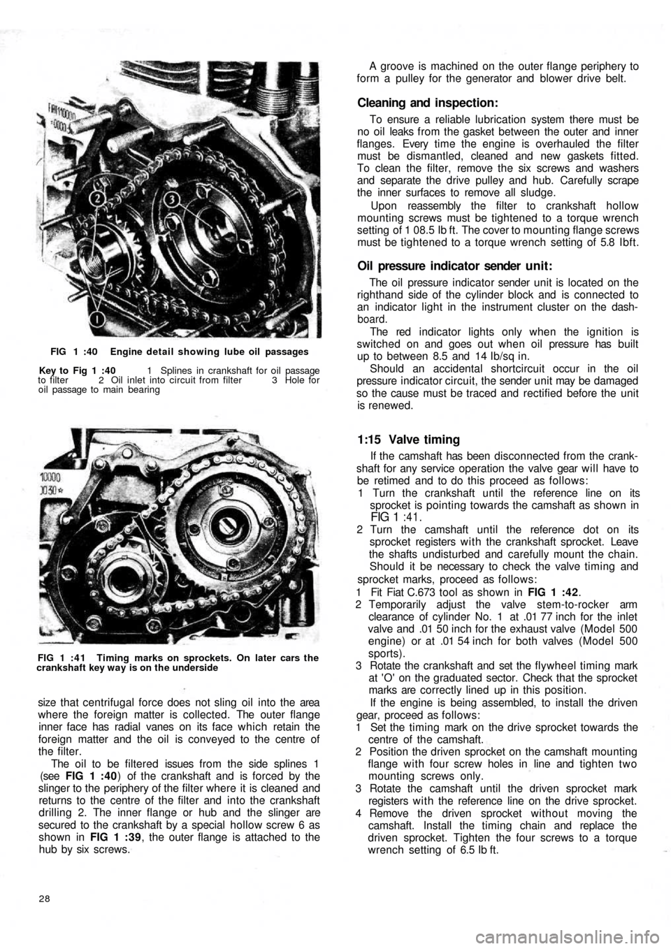
FIG 1 :40 Engine detail showing lube oil passages
Key to Fig 1 :40 1 Splines in crankshaft for oil passage
to filter 2 Oil inlet into circuit from filter 3 Hole for
oil passage to main bearing
FIG 1 : 4 1 Timing marks on sprockets. On later cars the
crankshaft key way is on the underside
size that centrifugal force does not sling oil into the area
where the foreign matter is collected. The outer flange
inner face has radial vanes on its face which retain the
foreign matter and the oil is conveyed to the centre of
the filter.
The oil to be filtered issues from the side splines 1
(see FIG 1 :40) of the crankshaft and is forced by the
slinger to the periphery of the filter where it is cleaned and
returns to the centre of the filter and into the crankshaft
drilling 2. The inner flange or hub and the slinger are
secured to the crankshaft by a special hollow screw 6 as
shown in FIG 1 :39, the outer flange is attached to the
hub by six screws.
28
If the camshaft has been disconnected from the crank-
shaft for any service operation the valve gear will have to
be retimed and to do this proceed as follows:
1 Turn the crankshaft until the reference line on its
sprocket is pointing towards the camshaft as shown in
FIG 1 :41.
2 Turn the camshaft until the reference dot on its
sprocket registers w i t h the crankshaft sprocket. Leave
the shafts undisturbed and carefully mount the chain.
Should it be necessary to check the valve timing and
sprocket marks, proceed as follows:
1 Fit Fiat C.673 tool as shown in FIG 1 :42.
2 Temporarily adjust the valve stem-to-rocker arm
clearance of cylinder No. 1 at .01 77 inch for the inlet
valve and .01 50 inch for the exhaust valve (Model 500
engine) or at .01 54 inch for both valves (Model 500
sports).
3 Rotate the crankshaft and set the flywheel timing mark
at 'O' on the graduated sector. Check that the sprocket
marks are correctly lined up in this position.
If the engine is being assembled, to install the driven
gear, proceed as follows:
1 Set the timing mark on the drive sprocket towards the
centre of the camshaft.
2 Position the driven sprocket on the camshaft mounting
flange with four screw holes in line and tighten two
mounting screws only.
3 Rotate the camshaft until the driven sprocket mark
registers w i t h the reference line on the drive sprocket.
4 Remove the driven sprocket without moving the
camshaft. Install the timing chain and replace the
driven sprocket. Tighten the four screws to a torque
wrench setting of 6.5 Ib ft.
1:15 Valve timing
The oil pressure indicator sender unit is located on the
righthand side of the cylinder block and is connected to
an indicator light in the instrument cluster on the dash-
board.
The red indicator lights only when the ignition is
switched on and goes out when o i l pressure has built
up to between 8.5 and 14 Ib/sq in.
Should an accidental shortcircuit occur in the oil
pressure indicator circuit, the sender unit may be damaged
so the cause must be traced and rectified before the unit
is renewed.
Oil pressure indicator sender unit:
To ensure a reliable lubrication system there must be
no oil leaks from the gasket between the outer and inner
flanges. Every t i m e t h e engine is overhauled the filter
must be dismantled, cleaned and new gaskets fitted.
To clean the filter, remove the six screws and washers
and separate the drive pulley and hub. Carefully scrape
the inner surfaces to remove all sludge.
Upon reassembly the filter to crankshaft hollow
mounting screws must be tightened to a torque wrench
setting of 1 08.5 Ib ft. The cover to mounting flange screws
must be tightened to a torque wrench setting of 5.8 Ibft.
Cleaning and inspection:
A groove is machined on the outer flange periphery to
form a pulley for the generator and blower drive belt.
Page 32 of 128
3 Engine warm-up:
As the engine begins to warm up to its normal operating
temperature, gradually push home the starting device
lever so as only to supply the engine with the richened
charge enabling the cold engine operation to be smooth
and regular. Position ' B ' (FIG 2:6).
4 Normal car driving:
Once the engine has reached its normal operating
temperature the starting device should be completely
brought out of operation by bringing the control lever to
the position 'C (FIG 2:6).
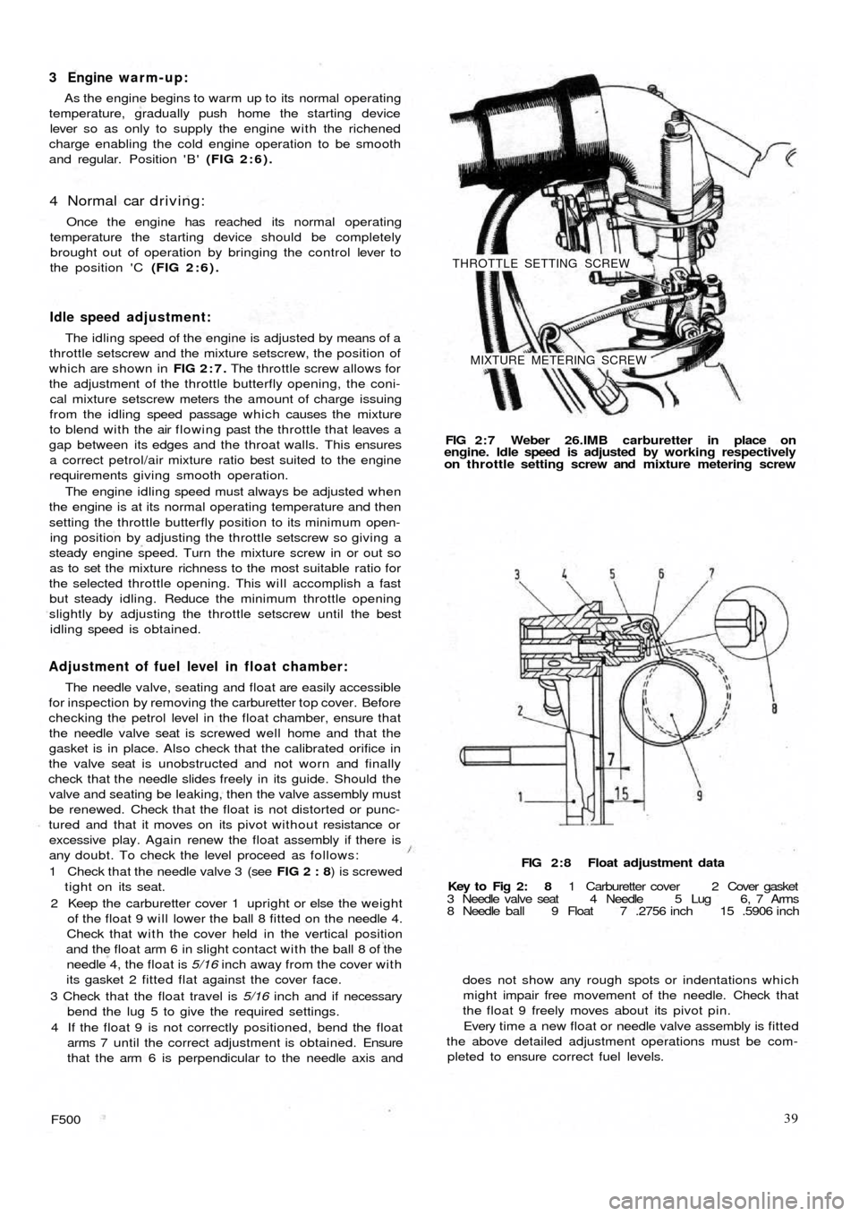
Idle speed adjustment:
The idling speed of the engine is adjusted by means of a
throttle setscrew and the mixture setscrew, the position of
which are shown in FIG 2:7. The throttle screw allows for
the adjustment of the throttle butterfly opening, the coni-
cal mixture setscrew meters the amount of charge issuing
from the idling speed passage which causes the mixture
to blend with the air flowing past the throttle that leaves a
gap between its edges and the throat walls. This ensures
a correct petrol/air mixture ratio best suited to the engine
requirements giving smooth operation.
The engine idling speed must always be adjusted when
the engine is at its normal operating temperature and then
setting the throttle butterfly position to its minimum open-
ing position by adjusting the throttle setscrew so giving a
steady engine speed. Turn the mixture screw in or out so
as to set the mixture richness to the most suitable ratio for
the selected throttle opening. This will accomplish a fast
but steady idling. Reduce the minimum throttle opening
slightly by adjusting the throttle setscrew until the best
idling speed is obtained.
Adjustment of fuel level in float chamber:
The needle valve, seating and float are easily accessible
for inspection by removing the carburetter top cover. Before
checking the petrol level in the float chamber, ensure that
the needle valve seat is screwed well home and that the
gasket is in place. Also check that the calibrated orifice in
the valve seat is unobstructed and not worn and finally
check that the needle slides freely in its guide. Should the
valve and seating be leaking, then the valve assembly must
be renewed. Check that the float is not distorted or punc-
tured and that it moves on its pivot without resistance or
excessive play. Again renew the float assembly if there is
any doubt. To check the level proceed as follows:
1 Check that the needle valve 3 (see FIG 2 : 8) is screwed
tight on its seat.
2 Keep the carburetter cover 1 upright or else the weight
of the float 9 will lower the ball 8 fitted on the needle 4.
Check that with the cover held in the vertical position
and the float arm 6 in slight contact with the ball 8 of the
needle 4, the float is 5/16 inch away from the cover with
its gasket 2
fitted flat against the cover face.
3 Check that the float travel is 5/16 inch and if necessary
bend the lug 5 to give the required settings.
4 If the float 9 is not correctly positioned, bend the float
arms 7 until the correct adjustment is obtained. Ensure
that the arm 6 is perpendicular to the needle axis and
F50039
does not show any rough spots or indentations which
might impair free movement of the needle. Check that
the float 9 freely moves about its pivot pin.
Every time a new float or needle valve assembly is fitted
the above detailed adjustment operations must be com-
pleted to ensure correct fuel levels. FIG 2 : 8 Float adjustment data
Key to Fig 2: 8 1 Carburetter cover 2 Cover gasket
3 Needle valve seat 4 Needle 5 Lug 6, 7 Arms
8 Needle ball 9 Float 7 .2756 inch 15 .5906 inch FIG 2 : 7 Weber 26.IMB carburetter in place on
engine. Idle speed is adjusted by working respectively
on throttle setting screw and mixture metering screw
THROTTLE SETTING SCREW
MIXTURE METERING SCREW
Page 33 of 128
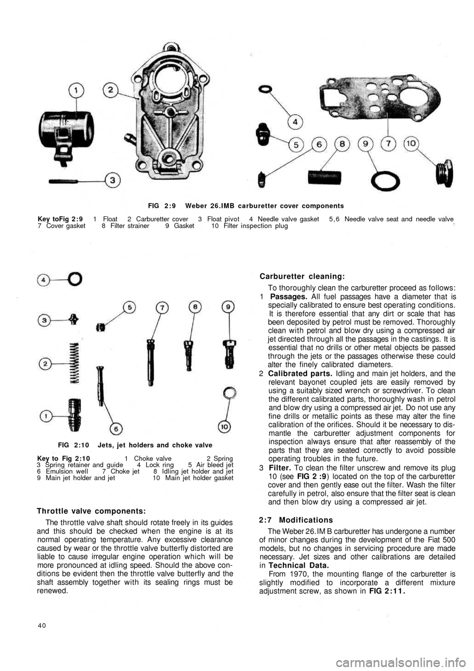
FIG 2 : 9 Weber 26.IMB carburetter cover components
Key toFig 2 : 9 1 Float 2 Carburetter cover 3 Float pivot 4 Needle valve gasket 5 , 6 Needle valve seat and needle valve
7 Cover gasket 8 Filter strainer 9 Gasket 10 Filter inspection plug
Carburetter cleaning:
To thoroughly clean the carburetter proceed as follows:
1 Passages. All fuel passages have a diameter that is
specially calibrated to ensure best operating conditions.
It is therefore essential that any dirt or scale that has
been deposited by petrol must be removed. Thoroughly
clean with petrol and blow dry using a compressed air
jet directed through all the passages in the castings. It is
essential that no drills or other metal objects be passed
through the jets or the passages otherwise these could
alter the finely calibrated diameters.
2 Calibrated parts. Idling and main jet holders, and the
relevant bayonet coupled jets are easily removed by
using a suitably sized wrench or screwdriver. To clean
the different calibrated parts, thoroughly wash in petrol
and blow dry using a compressed air jet. Do not use any
fine drills or metallic points as these may alter the fine
calibration of the orifices. Should it be necessary to dis-
mantle the carburetter adjustment components for
inspection always ensure that after reassembly of the
parts that they are seated correctly to avoid possible
operating troubles in the future.
3 Filter. To clean the filter unscrew and remove its plug
10 (see FIG 2 : 9) located on the top of the carburetter
cover and then gently ease o u t t h e filter. Wash the filter
carefully in petrol, also ensure that the filter seat is clean
and then blow dry using a compressed air jet.
2:7 Modifications
The Weber 26.IM B carburetter has undergone a number
of minor changes during the development of the Fiat 500
models, but no changes in servicing procedure are made
necessary. Jet sizes and other calibrations are detailed
in Technical Data.
From 1970, the mounting flange of the carburetter is
slightly modified to incorporate a different mixture
adjustment screw, as shown in FIG 2:11.
40
Throttle valve components:
The throttle valve shaft should rotate freely in its guides
and this should be checked when the engine is at its
normal operating temperature. Any excessive clearance
caused by wear or the throttle valve butterfly distorted are
liable to cause irregular engine operation which will be
more pronounced at idling speed. Should the above con-
ditions be evident then the throttle valve butterfly and the
shaft assembly together with its sealing rings must be
renewed.
FIG 2:10 Jets, jet holders and choke valve
Key to Fig 2:10 1 Choke valve 2 Spring
3 Spring retainer and guide 4 Lock ring 5 Air bleed jet
6 Emulsion well 7 Choke jet 8 Idling jet holder and jet
9 Main jet holder and jet 10 Main jet holder gasket
Page 36 of 128
1
14,5
7,52 9 48 35
76
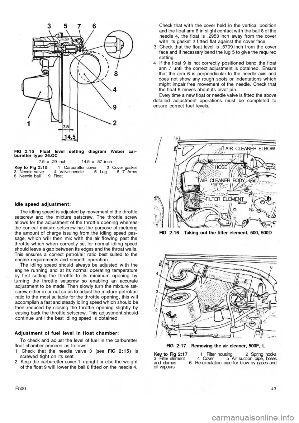
FIG 2:15 Float level setting diagram Weber car-
buretter type 26.OC
7.5 = .29 inch 14.5 = .57 inch
Key to Fig 2:15 1 Carburetter cover 2 Cover gasket
3 Needle valve 4 Valve needle 5 Lug 6, 7 Arms
8 Needle ball 9 Float
Idle speed adjustment:
The idling speed is adjusted by movement of the throttle
setscrew and the mixture setscrew. The throttle screw
allows for the adjustment of the throttle opening whereas
the conical mixture setscrew has the purpose of metering
the amount of charge issuing from the idling speed pas-
sage, which will then mix with the air flowing past the
throttle which when correctly set for normal idling speed
should leave a gap between its edges and the throat walls.
This ensures a correct petrol/air ratio best suited to the
engine requirements and smooth operation.
The idling speed should always be adjusted with the
engine running and at its normal operating temperature
by first setting the throttle to its minimum opening by
turning the throttle setscrew so enabling an accurate
adjustment to be made. Then slowly turn the mixture set-
screw either in or out so as to adjust the mixture petrol/air
ratio to the most suitable for the throttle opening, this will
accomplish a fast and steady idling speed which should be
then reduced by closing the throttle opening slightly by
easing back the throttle setscrew. This adjustment should
continue until the best idling speed is obtained.
Adjustment of fuel level in float chamber:
To check and adjust the level of fuel in the carburetter
float chamber proceed as follows:
1 Check that the needle valve 3 (see FIG 2:15) is
screwed tight on its seat.
2 Keep the carburetter cover 1 upright or else the weight
of the float 9 will lower the ball 8 fitted on the needle 4.
F50043
Key to Fig 2:17 1 Filter housing 2 Spring hooks
3 Filter element 4 Cover 5 Air suction pipe, hoses
and clamps 6 Re-circulation pipe for blow-by gases and
oil vapoursFIG 2:17 Removing the air cleaner, 500F, L
2
1 3
4.
6
5
FIG 2:16 Taking out the filter element, 500, 500D AIR CLEANER ELBOW
HOSE
AIR CLEANER BODY
FILTER ELEMENT Check that with the cover held in the vertical position
and the float arm 6 in slight contact with the ball 8 of the
needle 4, the float is .2953 inch away from the cover
w i t h its gasket 2 fitted flat against the cover face.
3 Check that the float level is .5709 inch from the cover
face and if necessary bend the lug 5 to give the required
setting.
4 If the float 9 is not correctly positioned bend the float
arm 7 until the correct adjustment is obtained. Ensure
that the arm 6 is perpendicular to the needle axis and
does not show any rough spots or indentations which
might impair free movement of the needle. Check that
the float 9 moves about its pivot pin.
Every time a new float or needle valve is fitted the above
detailed adjustment operations must be completed to
ensure correct fuel levels.
Page 38 of 128
Air cleaner—station wagon:
A pleated paper air cleaner element is housed in a
special air intake chamber connected to the front of the
engine air cooling cowling (see FIG 4 : 2) . This chamber
will be seen located towards the rear of t h e power unit
compartment. Remove the retaining wing nut, lift off the
lid and the element can be withdrawn by lifting upwards.
2:10 Blow-by-gases recirculation device
Engine 110 F.000
All the oil vapours and blow-by-gases that are formed
in the engine crankcase are drawn to the cylinder head
cover recess 1 (see FIG 2:18). From here they travel into
the pipe 5 via a breather valve 2 which is firmly attached to
the oil filler cap 3 and the strainer 4 located in the filler
neck. The oil vapours and gases are then d r a w n back into
the duct 9 from the pipe 5 which connects the air cleaner
6 to the carburetter 7. This ensures a complete closed cir-
cuit circulation.
Engine 120.000:
From engine No. 288156 the oil vapours and blow-by-
gases instead of being exhausted to the atmosphere are
conveyed to the air cleaner and from here they are drawn
back into the combustion chambers. To ensure that an
excessive of oil vapour does not pass along the piping
with the blow-by-gases a diaphragm is fitted in the duct
in front of the breather valve 2 (see FIG 2 :18), the dia-
phragm comprising a filter gauze 11 and moveable parti-
tion 10.
It should be noted that the oil vapour strainer 4 (see
FIG 2:18) and the flame trap 8 can easily be removed
from their seating for cleaning or renewal.
2 : 1 1 Fuel tank
The fuel tank is located in the front compartment as
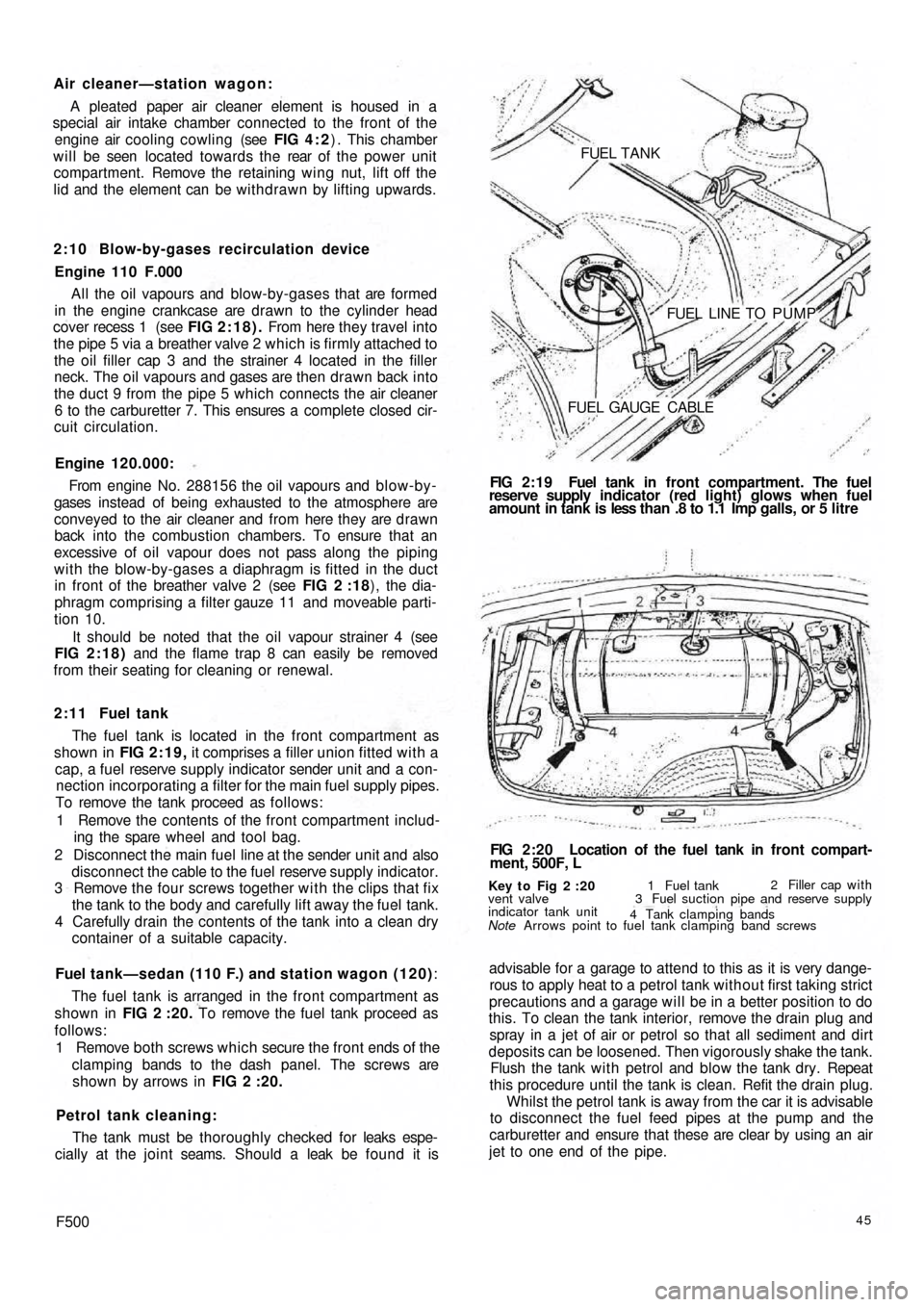
shown in FIG 2:19, it comprises a filler union fitted with a
cap, a fuel reserve supply indicator sender unit and a con-
nection incorporating a filter for the main fuel supply pipes.
To remove the tank proceed as follows:
1 Remove the contents of the front compartment includ-
ing the spare wheel and tool bag.
2 Disconnect the main fuel line at the sender unit and also
disconnect the cable to the fuel reserve supply indicator.
3 Remove the four screws together w i t h the clips that fix
the tank to the body and carefully lift away the fuel tank.
4 Carefully drain the contents of the tank into a clean dry
container of a suitable capacity.
Fuel tank—sedan (110 F.) and station wagon (120):
The fuel tank is arranged in the front compartment as
shown in FIG 2 :20. To remove the fuel tank proceed as
follows:
1 Remove both screws which secure the front ends of the
clamping bands to the dash panel. The screws are
shown by arrows in FIG 2 :20.
Petrol tank cleaning:
The tank must be thoroughly checked for leaks espe-
cially at the joint seams. Should a leak be found it is
F50045
advisable for a garage to attend to this as it is very dange-
rous to apply heat to a petrol tank without first taking strict
precautions and a garage will be in a better position to do
this. To clean the tank interior, remove the drain plug and
spray in a jet of air or petrol so that all sediment and dirt
deposits can be loosened. Then vigorously shake the tank.
Flush the tank w i t h petrol and blow the tank dry. Repeat
this procedure until the tank is clean. Refit the drain plug.
Whilst the petrol tank is away from the car it is advisable
to disconnect the fuel feed pipes at the pump and the
carburetter and ensure that these are clear by using an air
jet to one end of the pipe.
Key t o Fig 2 :20
Note Arrows point to fuel tank clamping band screws vent valve
indicator tank unit1 Fuel tank2 Filler cap with
3 Fuel suction pipe and reserve supply
4 Tank clamping bands
FIG 2:20 Location of the fuel tank in front compart-
ment, 500F, L FIG 2:19 Fuel tank in front compartment. The fuel
reserve supply indicator (red light) glows when fuel
amount in tank is less than .8 to 1.1 Imp galls, or 5 litre FUEL TANK
FUEL LINE TO PUMP
FUEL GAUGE CABLE
Page 41 of 128
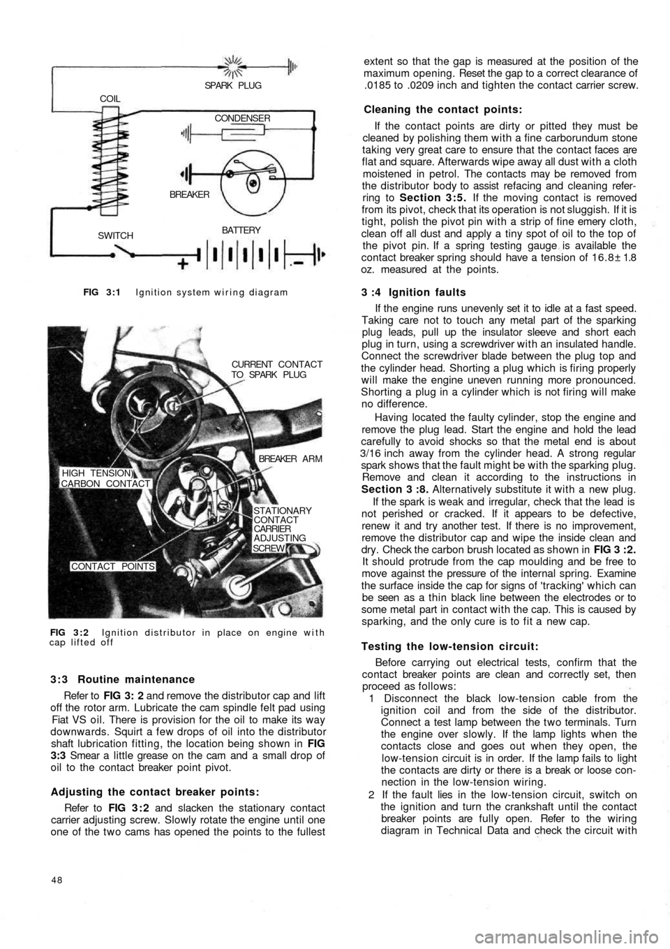
FIG 3 : 1 Ignition system wiring diagram
BATTERY
SWITCHBREAKER COIL
SPARK PLUG
CONDENSER
FIG 3 : 2 Ignition distributor in place on engine with
cap lifted offCURRENT CONTACT
TO SPARK PLUG
BREAKER A R M
STATIONARY
CONTACT
CARRIER
ADJUSTING
SCREW
CONTACT POINTS HIGH TENSION)
CARBON CONTACT
3 : 3 Routine maintenance
Refer to FIG 3: 2 and remove the distributor cap and lift
off the rotor arm. Lubricate the cam spindle felt pad using
Fiat VS oil. There is provision for the oil to make its way
downwards. Squirt a few drops of oil into the distributor
shaft lubrication fitting, the location being shown in FIG
3:3 Smear a little grease on the cam and a small drop of
oil to the contact breaker point pivot.
Adjusting the contact breaker points:
Refer to FIG 3 : 2 and slacken the stationary contact
carrier adjusting screw. Slowly rotate the engine until one
one of the t w o cams has opened the points to the fullest
48
extent so that the gap is measured at the position of the
maximum opening. Reset the gap to a correct clearance of
.0185 to .0209 inch and tighten the contact carrier screw.
Cleaning the contact points:
If the contact points are dirty or pitted they must be
cleaned by polishing them with a fine carborundum stone
taking very great care to ensure that the contact faces are
flat and square. Afterwards wipe away all dust with a cloth
moistened in petrol. The contacts may be removed from
the distributor body to assist refacing and cleaning refer-
ring to Section 3:5. If the moving contact is removed
from its pivot, check that its operation is not sluggish. If it is
tight, polish the pivot pin with a strip of fine emery cloth,
clean off all dust and apply a tiny spot of oil to the top of
the pivot pin. If a spring testing gauge is available the
contact breaker spring should have a tension of 16.8± 1.8
oz. measured at the points.
3 :4 Ignition faults
If the engine runs unevenly set it to idle at a fast speed.
Taking care not to touch any metal part of the sparking
plug leads, pull up the insulator sleeve and short each
plug in turn, using a screwdriver with an insulated handle.
Connect the screwdriver blade between the plug top and
the cylinder head. Shorting a plug which is firing properly
will make the engine uneven running more pronounced.
Shorting a plug in a cylinder which is not firing will make
no difference.
Having located the
faulty cylinder, stop the engine and
remove the plug lead. Start the engine and hold the lead
carefully to avoid shocks so that the metal end is about
3/16 inch away from the cylinder head. A strong regular
spark shows that the fault might be with the sparking plug.
Remove and clean it according to the instructions in
Section 3 :8. Alternatively substitute it with a new plug.
If the spark is weak and irregular, check that the lead is
not perished or cracked. If it appears to be defective,
renew it and try another test. If there is no improvement,
remove the distributor cap and wipe the inside clean and
dry. Check the carbon brush located as shown in FIG 3 : 2 .
It should protrude from the cap moulding and be free to
move against the pressure of the internal spring. Examine
the surface inside the cap for signs of 'tracking' which can
be seen as a thin black line between the electrodes or to
some metal part in contact with the cap. This is caused by
sparking, and the only cure is to fit a new cap.
Testing the low-tension circuit:
Before carrying out electrical tests, confirm that the
contact breaker points are clean and correctly set, then
proceed as follows:
1 Disconnect the black low-tension cable from the
ignition coil and from the side of the distributor.
Connect a test lamp between the t w o terminals. Turn
the engine over slowly. If the lamp lights when the
contacts close and goes out when they open, the
low-tension circuit is in order. If the lamp fails to light
the contacts are dirty or there is a break or loose con-
nection in the low-tension wiring.
2 If the fault lies in the
low-tension circuit, switch on
the ignition and turn the crankshaft until the contact
breaker points are fully open. Refer to the wiring
diagram in Technical Data and check the circuit with
Page 43 of 128
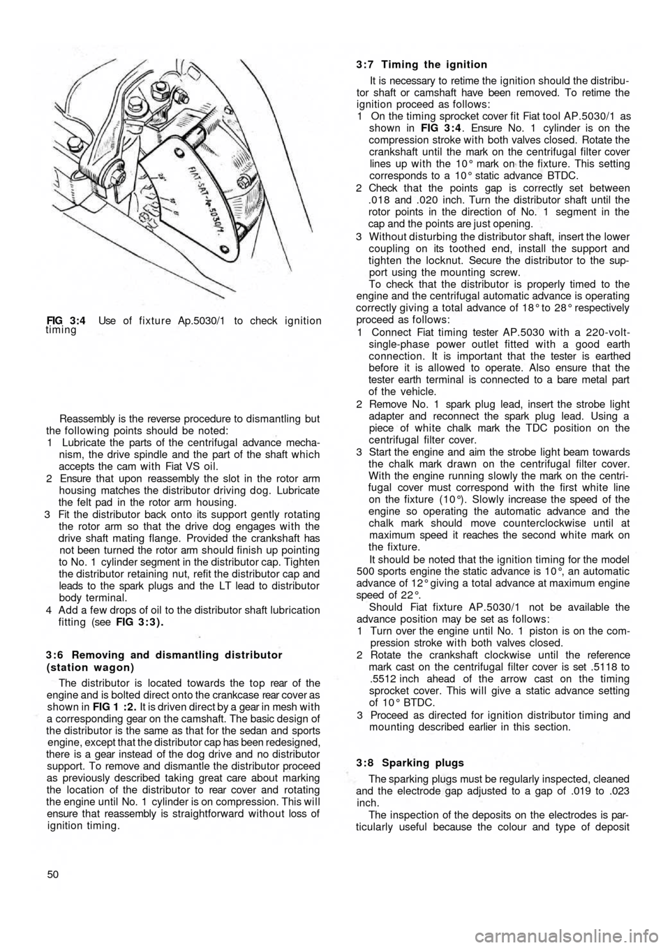
FIG 3 : 4 Use of fixture Ap.5030/1 to check ignition
timing
Reassembly is the reverse procedure to dismantling but
the following points should be noted:
1 Lubricate the parts of the centrifugal advance mecha-
nism, the drive spindle and the part of the shaft which
accepts the cam w i t h Fiat VS oil.
2 Ensure that upon reassembly the slot in the rotor arm
housing matches the distributor driving dog. Lubricate
the felt pad in the rotor arm housing.
3 Fit the distributor back onto its support gently rotating
the rotor arm so that the drive dog engages w i t h the
drive shaft mating flange. Provided the crankshaft has
not been turned the rotor arm should finish up pointing
to No. 1 cylinder segment in the distributor cap. Tighten
the distributor retaining nut, refit the distributor cap and
leads to the spark plugs and the LT lead to distributor
body terminal.
4 Add a few drops of oil to the distributor shaft lubrication
fitting (see FIG 3:3).
3 : 6 Removing and dismantling distributor
(station wagon)
The distributor is located towards the top rear of t h e
engine and is bolted direct onto the crankcase rear cover as
shown in FIG 1 : 2 . It is driven direct by a gear in mesh w i t h
a corresponding gear on the camshaft. The basic design of
the distributor is the same as that for the sedan and sports
engine, except that the distributor cap has been redesigned,
there is a gear instead of the dog
drive and no distributor
support. To remove and dismantle the distributor proceed
as previously described taking great care about marking
the location of the distributor to rear cover and rotating
the engine until No. 1 cylinder is on compression. This will
ensure that reassembly is straightforward without loss of
ignition timing.
503:7 Timing the ignition
It is necessary to retime the ignition should the distribu-
tor shaft or camshaft have been removed. To retime the
ignition proceed as follows:
1 On the timing sprocket cover fit Fiat tool AP.5030/1 as
shown in FIG 3 : 4. Ensure No. 1 cylinder is on the
compression stroke with both valves closed. Rotate the
crankshaft until the mark on the centrifugal filter cover
lines up w i t h the 10° mark on the fixture. This setting
corresponds to a 10° static advance BTDC.
2 Check t h a t the points gap is correctly set between
.018 and .020 inch. Turn the distributor shaft until the
rotor points in the direction of No. 1 segment in the
cap and the points are just opening.
3 Without disturbing the distributor shaft, insert the lower
coupling on its toothed end, install the support and
tighten the locknut. Secure the distributor to the sup-
port using the mounting screw.
To check that the distributor is properly timed to the
engine and the centrifugal automatic advance is operating
correctly giving a
total advance of 18° to 28° respectively
proceed as follows:
1 Connect Fiat timing tester AP.5030 with a 220-volt-
single-phase power outlet fitted with a good earth
connection. It is important that the tester is earthed
before it is allowed to operate. Also ensure that the
tester earth terminal is connected to a bare metal part
of the vehicle.
2 Remove No. 1 spark plug lead, insert the strobe light
adapter and reconnect the spark plug lead. Using a
piece of white chalk mark the TDC position on the
centrifugal filter cover.
3 Start the engine and aim the strobe light beam towards
the chalk mark drawn on the centrifugal filter cover.
With the engine running slowly the mark on the centri-
fugal cover must correspond wi th the first white line
on the fixture (10°). Slowly increase the speed of the
engine so operating the automatic advance and the
chalk mark should move counterclockwise until at
maximum speed it reaches the second white mark on
the fixture.
It should be noted that the ignition timing for the model
500 sports engine the static advance is 10°, an automatic
advance of 12° giving a total advance at maximum engine
speed of 2 2 ° .
Should Fiat fixture AP.5030/1 not be available the
advance position may be set as follows:
1 Turn over the
engine until No. 1 piston is on the com-
pression stroke w i t h both valves closed.
2 Rotate the crankshaft clockwise until the reference
mark cast on the centrifugal filter cover is set .5118 to
.5512 inch ahead of the arrow cast on the timing
sprocket cover. This will give a static advance setting
of 10° BTDC.
3 Proceed as directed for ignition distributor timing and
mounting described earlier in this section.
3 : 8 Sparking plugs
The sparking plugs must be regularly inspected, cleaned
and the electrode gap adjusted to a gap of .019 to .023
inch.
The inspection of the deposits on the electrodes is par-
ticularly useful because the colour and type of deposit