hubs FIAT 500 1967 1.G Workshop Manual
[x] Cancel search | Manufacturer: FIAT, Model Year: 1967, Model line: 500, Model: FIAT 500 1967 1.GPages: 128, PDF Size: 9.01 MB
Page 58 of 128

CHAPTER 6
GEARBOX AND DIFFERENTIAL UNIT
6:1
6:2
6:3
6:4
6:5
6:6Description
Removal of gearbox/differential unit
Dismantling — gearbox
Reassembly — gearbox
Dismantling — differential and final drive
Reassembly— differential and final drive6:7
6:8
6:9
6:10
6:11
6:12Final drive gear set adjustment
Replacement of gearbox/differential unit
Swing axle shafts and slip joints
Gear shift control mechanism
Modifications
Fault diagnosis
6 :1 Description
The gearbox and differential unit are housed in an
aluminium alloy casing made up of t w o parts which split
at the differential centre line. The output drive is trans-
mitted by means of t w o half axle drive shafts coupled
through wheel shafts and slip joints to the rear wheels (see
FIG 6 : 1)
The gearbox provides four forward-speeds and a reverse,
the fourth-speed being considered as an overdrive. All
gears except first and reverse gears, which are straight
toothed sliding gears, are in constant mesh and have heli-
cal teeth. No synchromesh is provided, gear engagement
being completed by sliding shifter sleeves of the dog
clutch type. The first-speed gear slides on the outside of
the third and fourth shifter sleeve, whilst the reverse gear
train moves on a fixed shaft. The clutch shaft is integral
with the third, top and combined and first and second gear
pinions, whilst the second gear pinion is splined at the
front end. An internal splined
coupling sleeve joins the
clutch shaft and the input shaft and transmits the power
from the engine to the gearbox. The mainshaft and
differential drive pinion are combined together and besides
carrying the constant mesh gears and the sliding first gear
pinion, it also has attached the sliding sleeves and hubs.
F50065 The speedometer drive pinion is located at the front end.
The gearbox/differential casing is attached to the engine
by six studs which locate in the crankcase. The front of the
unit rests upon the rubber mounted support which is
secured to the body floor.
The complete unit comprises three detachable parts
made up as follows:
1 The support for the connection of the gearbox to the
engine which also acts as part of the differential front
end and clutch/flywheel housing at rear.
2 A central body which is divided into two compartments.
The front compartment contains first, third, fourth and
reverse gears w i t h the primary shaft, layshaft and reverse
shaft as well as the necessary gear selection striker rods
and forks. The rear of this compartment also forms a half
cover for the differential unit.
3 The gearbox casing cover, which contains the second-
speed gears together with the relative fork, gear
selection rod and speedometer drive gears.
The central part of the casing is provided with a top
inspection cover. The primary shaft is coupled to the clutch
shaft through an internally splined sleeve and t w o pins
which are retained by rings. The primary shaft together
with the first, third and fourth driving gears form a cluster.
Page 63 of 128

3 Check the layshaft and the primary shaft between
centres and using a dial gauge ensure that there is no
distortion. The out of true reading for bearing seats
should be less than .0008 inch. Inspect the splines and
ensure that the side and outerfaces are not indented.
Replace if there are signs of wear. Also inspect the
reverse shaft to ensure that it is perfectly smooth and
not showing signs of pitting or partial seizure.
4 Carefully inspect all gear teeth for signs of excessive
wear or damage. The contact faces must be smooth and
show no signs of indentation marks. Also check that
the backlash between the gears, when correctly
mounted on the surface plate is not greater than .0039
inch. The maximum wear limit is .0079 inch. Check that
the quick engagement front teeth of the second-, third-
and fourth-speed gears are not damaged or excessively
worn. Renew if there are signs of gearchange lever
misuse.
5 Inspect the sliding sleeves and the relevent hubs, ensure
that all the working surfaces are perfectly smooth. The
clearance between the mating parts should not be
greater than .0059 inch. Also inspect the meshing teeth
and ensure that they are in good condition.
6 Check that the gear shifting selector forks are not dis-
torted and that the striker rods freely slide in their seats
in the gearbox casing.
7 Carefully inspect that all the oil seals are in perfect con-
dition and if there is any doubt they should be renewed.
8 Inspect the striker rod locking balls and the safety rollers
and ensure that they slide freely in their seatings. Also
check the ball load spring efficiency and if this shows
signs of weakness then it should be renewed. Any
faults with these items will cause difficulty in engaging
gears or autodisengagement during engine acceleration.
6 : 4 Reassembly—gearbox
To reassemble the components to the gearbox ensure
that all components are thoroughly clean and then pro-
ceed as follows:
1 Press t h e pinion rear roller bearing onto the layshaft.
Install the layshaft in the casing, and at the same time
fit the adjustment shim, the fourth-speed driven gear
together w i t h its bush, the sleeve and hub for third and
fourth gear engagement, the first-speed and reverse
driven gear and the third-speed driven gear with its
hub.
2 Install the front layshaft ballbearing securing the
bearing retainment plate w i t h the screws and finally
lock the screws in position.
3 Insert the primary shaft together with the first, third
and fourth driving gear train in the gearbox housing
and slide t h e rear bearing onto the shaft. Push the
input shaft forward to enable the clutch shaft coupling
to be inserted in t h e rear and to be pulled up the
primary shaft by means of the pin. Do not forget the
retaining ring.
4 Slide the primary shaft backwards so pushing the rear
bearing into its bore. Refit the front bearing onto the
primary shaft.
5 On the layshaft insert the second-speed driven shaft
and bush, the second gear sliding dog sleeve and the
hub. Also insert the second-speed striker rod and the
first-speed fork. Do not forget to fit the safety roller
into its seating.
70
6 Slide the second-speed driving gear onto the primary
shaft. Place the engagement fork on the third- and
fourth-speed engagement sliding sleeve, and insert
the striker rod, lock the relevent fork and fit the safety
roller.
7 Insert the third safety roller and install the reverse shaft
and insert the reverse gear cluster onto it and secure
the shaft by tightening its block bolt. Install the reverse
striker rod w i t h its relevent fork.
8 Now refit the speedometer drive worm gear onto the
layshraft. Tighten the nuts on the primary shaft and the
layshaft, not forgetting to interpose the plain washer
between the speedometer driving worm and the nut,
to a torque wrench setting of 1 8.1 Ib ft to 25.3 Ib ft
(primary shaft) and 28.9 to 36.2 Ib ft (layshaft). It is
recommended that the input shaft and layshaft are
locked together by engaging t w o gears at the same
time. Finally, fit the splitpins.
9 Lock the shifter forks onto their shafts by tightening
their respective bolts and bend up the special locking
plates. Install the three positioning balls and relevant
springs into their bores and refit the cover plate.
10 Install the casing cover together with its relevant
gasket. This will enable correct positioning of the shift
shaft lever so that it engages in the outer ends of the
shifter shafts protruding from the gearbox casing.
11 Install the speedometer drive support on the gearbox
casing and refit the upper gearbox cover.
For subsequent differential operations and adjustments
see Sections 6:6.
6:5 Dismantling—differential and final drive
For the removal of the differential and final drive unit
from the gearbox refer to Section 6:3. To dismantle the
differential assembly
proceed as follows:
1 Remove the retaining ring 2 (see FIG 6 : 7) retaining
the splined sleeve 4 and slide the sleeve off the drive
shaft.
2 Remove t h e retaining covers 7 and the oil boots all
together with the bushes and seals, adjuster ring lock
rings 13, adjuster rings housing 14, and bearing
adjuster and roller bearing outer races.
3 Separate the differential housing halves by unscrewing
and removing the six bolts that keep both the halves and
the crownwheel together. It is advisable to mark the
respective components to ensure correct matching
upon reassembly.
4 Remove the differential pinion shaft retainer ring, also
the differential pinions 10 by removing the shaft and
withdrawing the two axle shafts 1.
5 Remove the differential side gears 6 and relevent thrust
rings 8.
6 Using a press remove the differential bearing inner
races from their seats on the carrier halves.
7 Thoroughly clean all parts and dry using a compressed
air jet.
Inspection:
The components of the differential unit must be
thoroughly inspected for correct operation and to deter-
mine the presence of any wear, damage or other irregulari-
ties. To check the items concerned proceed as follows:
1 Check thoroughly the idle pinion carrier shaft for signs
Page 80 of 128

CHAPTER 8
FRONT SUSPENSION AND HUBS
8:1
8:2
8:3
8:4
8:5
8:6Description
Front suspension removal and dismantling
Leaf spring
Swinging arms
Kingpin housing
Steering knuckle and wheel hub
8:1 Description
The independent front suspension assembly fitted to
the 'new 500' range comprises a transverse leaf spring
which is anchored to the body through two rubber
mountings and kingpins through 'estendblocks' as
shown in FIG 8:1. The leaf spring also acts as an anti-
roll bar which gives normal spring reaction even when the
front road wheels encounter a rough road surface.
Special polyethylene insulating strips are fitted
between the five springs leaves which are all clamped
together by t w o rubber cushioned clamps.
Upper movement of the kingpins in the swinging arm
is obtained by 'estendblocks'. The half arms are anchored
to the body as shown in FIG 8 : 3 and pivot on their pins
through rubber bushes. Double acting hydraulic shock
absorbers are fitted to the kingpin housings at the lower
end and anchored at the top to the vehicle body. Two
rubber buffers are secured to brackets mounted onto the
body to limit the spring oscillations. The spring centre
bolt is also fitted with a rubber pad.
8 : 2 Front suspension removal and
dismantling
To remove the front suspension assembly proceed as
follows:
F50087
1 Remove the hub caps and carefully slacken the road
wheel retaining bolts. Using a garage hydraulic jack
raise the front of the vehicle and place on firmly
based stands. Remove the road wheels.
2 Disconnect the steering linkages from the pitman arm,
the drag link and the steering knuckle arms.
3 Remove the shock absorber upper mounting nut from
the body, lift away the half rubber bush and push d o w n
the outer cylinder.
4 Blank off the brake fluid reservoir outlet by inserting
a suitable wooden peg through the reservoir filler
opening and disconnect the brake hydraulic lines at
the wheel cylinders.
5 Fit Fiat crossbeam Arr.2072 under the leaf spring
and support this, using a garage hydraulic jack.
6 Remove the self-locking nut securing the leaf spring
to the kingpin housing and ease o u t the spring
mounting bolt taking care not to damage the thread.
Also remove the nuts securing the swinging arm pin
to studs on the body and remove the swinging arm
assembly. Carefully lift out the adjusting shims and
spacers from the studs making a careful note of the
number of the shims and their locations.
7 Remove the nuts securing the leaf spring elastic
mounting to the body (see FIG 8 : 4) , and lower the 8:7
8:8
8:9
8:10
8:11Hydraulic damper
Front suspension assembly and
installation
Steering geometry
Modifications
Fault diagnosis
Page 87 of 128

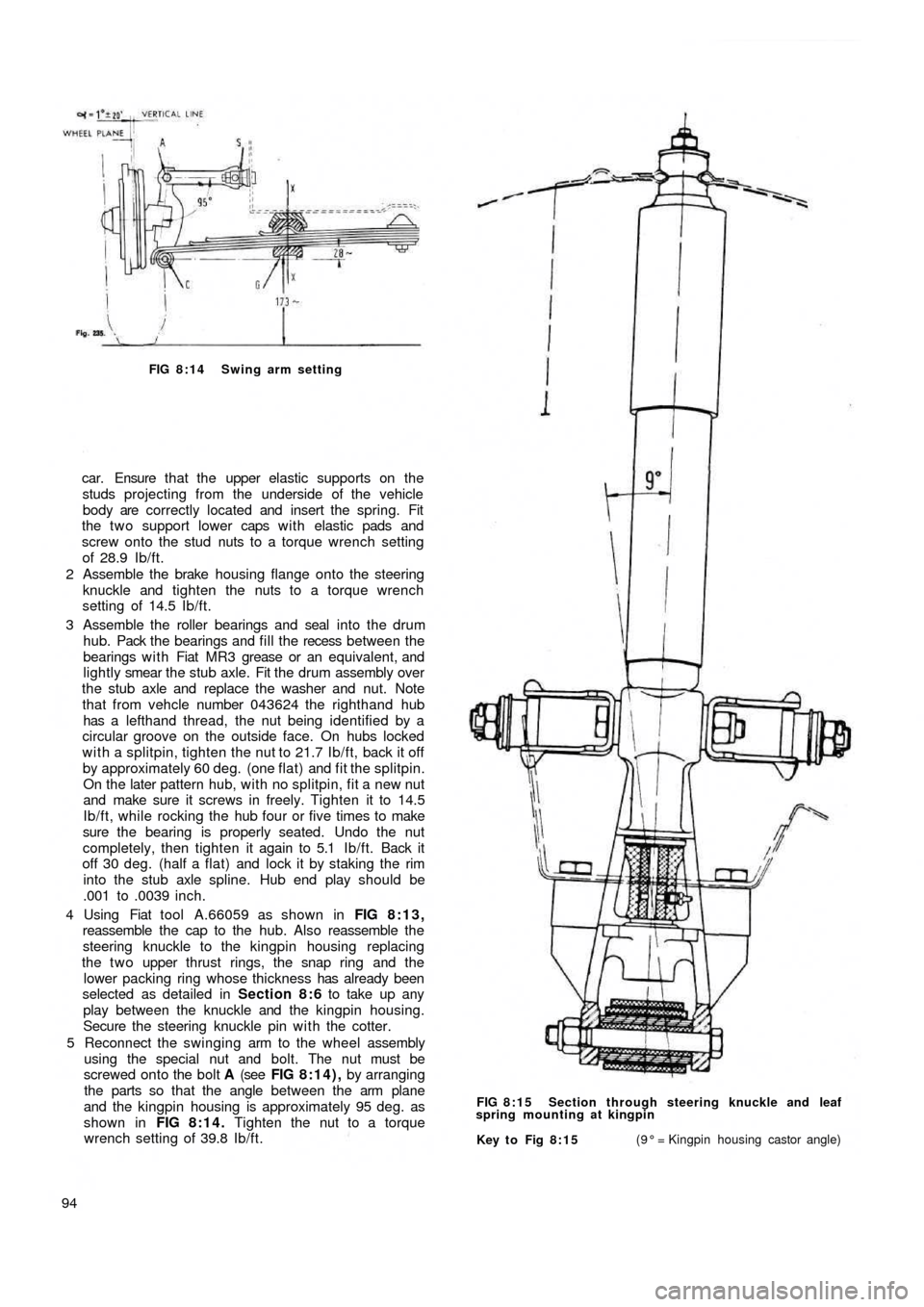
FIG 8:14 Swing arm setting
car. Ensure t h a t the upper elastic supports on the
studs projecting from the underside of the vehicle
body are correctly located and insert the spring. Fit
the two support lower caps w i t h elastic pads and
screw onto the stud nuts to a torque wrench setting
of 28.9 Ib/ft.
2 Assemble the brake housing flange onto the steering
knuckle and tighten the nuts to a torque wrench
setting of 14.5 Ib/ft.
3 Assemble the roller bearings and seal into the drum
hub. Pack the bearings and fill the recess between the
bearings w i t h Fiat MR3 grease or an equivalent, and
lightly smear the stub axle. Fit the drum assembly over
the stub axle and replace the washer and nut. Note
that from vehcle number 043624 the righthand hub
has a lefthand thread, the nut being identified by a
circular groove on the outside face. On hubs locked
with a splitpin, tighten the nut to 21.7 Ib/ft, back it off
by approximately 60 deg. (one flat) and fit the splitpin.
On the later pattern hub, with no splitpin, fit a new nut
and make sure it screws in freely. Tighten it to 14.5
Ib/ft, while rocking the hub four or five times to make
sure the bearing is properly seated. Undo the nut
completely, then tighten it again to 5.1 Ib/ft. Back it
off 30 deg. (half a flat) and lock it by staking the rim
into the stub axle spline. Hub end play should be
.001 to .0039 inch.
4 Using Fiat tool A.66059 as shown in FIG 8:13,
reassemble the cap to the hub. Also reassemble the
steering knuckle to the kingpin housing replacing
the t w o upper
thrust rings, the snap ring and the
lower packing ring whose thickness has already been
selected as detailed in Section 8:6 to take up any
play between the knuckle and the kingpin housing.
Secure the steering knuckle pin with the cotter.
5 Reconnect the swinging arm to the wheel assembly
using the special nut and bolt. The nut must be
screwed onto the bolt A (see FIG 8:14), by arranging
the parts so that the angle between the arm plane
and the kingpin housing is approximately 95 deg. as
shown in FIG 8:14. Tighten the nut to a torque
wrench setting of 39.8 Ib/ft.
94
Key to Fig 8:15(9° = Kingpin housing castor angle) FIG 8:15 Section through steering knuckle and leaf
spring mounting at kingpin