Fuel line FIAT 500 1969 1.G Workshop Manual
[x] Cancel search | Manufacturer: FIAT, Model Year: 1969, Model line: 500, Model: FIAT 500 1969 1.GPages: 128, PDF Size: 9.01 MB
Page 9 of 128
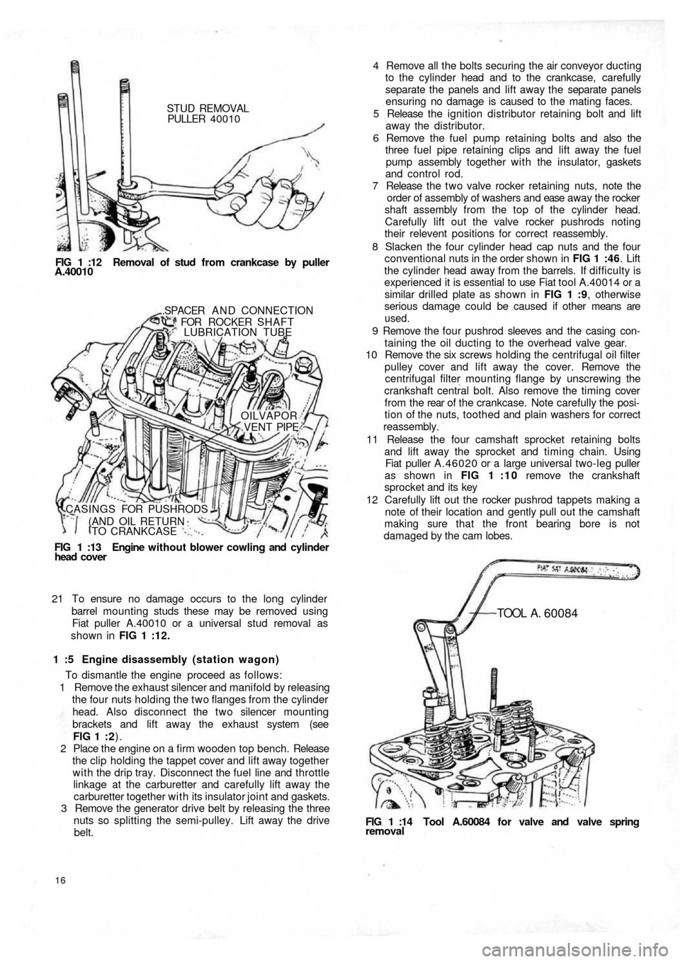
STUD REMOVAL
PULLER 40010
FIG 1 :12 Removal of stud from crankcase by puller
A.40010
FIG 1 :13 Engine without blower cowling and cylinder
head cover.SPACER A N D CONNECTION
FOR ROCKER SHAFT
LUBRICATION TUBE
OILVAPOR
.VENT PIPE
CASINGS FOR PUSHRODS
(AND OIL RETURN
TO CRANKCASE
21 To ensure no damage occurs to the long cylinder
barrel mounting studs these may be removed using
Fiat puller A.40010 or a universal stud removal as
shown in FIG 1 :12.
1 :5 Engine disassembly (station wagon)
To dismantle the engine proceed as follows:
1 Remove the exhaust silencer and manifold by releasing
the four nuts holding the two flanges from the cylinder
head. Also disconnect the two silencer mounting
brackets and lift away the exhaust system (see
FIG 1 : 2).
2 Place the engine on a firm wooden top bench. Release
the clip holding the tappet cover and lift away together
with the drip tray. Disconnect the fuel line and throttle
linkage at the carburetter and carefully lift away the
carburetter together with its insulator joint and gaskets.
3 Remove the generator drive belt by releasing the three
nuts so splitting the semi-pulley. Lift away the drive
belt.
16
FIG 1 :14 Tool A.60084 for valve and valve springremoval
TOOL A . 60084
4 Remove all the bolts securing the air conveyor ducting
to the cylinder head and to the crankcase, carefully
separate the panels and lift away the separate panels
ensuring no damage is caused to the mating faces.
5 Release the ignition distributor retaining bolt and lift
away the distributor.
6 Remove the fuel pump retaining bolts and also the
three fuel pipe retaining clips and lift away the fuel
pump assembly together with the insulator, gaskets
and control rod.
7 Release the t w o valve rocker retaining nuts, note the
order of assembly of washers and ease away the rocker
shaft assembly from the top of the cylinder head.
Carefully lift out the valve rocker pushrods noting
their relevent positions for correct reassembly.
8 Slacken the four cylinder head cap nuts and the four
conventional nuts in the order shown in FIG 1 :46. Lift
the cylinder head away from the barrels. If difficulty is
experienced it is essential to use Fiat tool A.40014 or a
similar drilled plate as shown in FIG 1 :9, otherwise
serious damage could be caused if other means are
used.
9 Remove the four pushrod sleeves and the casing con-
taining the oil ducting to the overhead valve gear.
10 Remove the six screws holding the centrifugal oil filter
pulley cover and lift away the cover. Remove the
centrifugal filter mounting flange by unscrewing the
crankshaft central bolt. Also remove the timing cover
f r o m t h e rear of t h e crankcase. Note carefully the posi-
tion of the nuts, toothed and plain washers for correct
reassembly.
11 Release the four camshaft sprocket retaining bolts
and lift away the sprocket and timing chain. Using
Fiat puller A.46020 or a large universal two-leg puller
as shown in FIG 1 : 1 0 remove the crankshaft
sprocket and its key
12 Carefully lift out the rocker pushrod tappets making a
note of their location and gently pull out the camshaft
making sure that the front bearing bore is not
damaged by the cam lobes.
Page 12 of 128
Cylinder head installation:
To refit the cylinder head proceed as follows:
Place a new cylinder head joint on the cleaned faces of
the cylinder barrels. Insert the rocker pushrod and
lubrication pipe sleeves together with the relevant
gaskets and rings.
Fit the washers and nuts to the studs and tighten to
fingertight.
Tighten the nuts in the order shown in FIG 1 :44 and
FIG 1 :46 to a torque wrench setting of 18.1 Ibft. Reset
the torque wrench to a new setting of 23.9 Ibft and
tighten the nuts once more in the recommended order.
Replace the pushrods in the correct order.
Refit the rocker shaft ensuring correct location of the
lubrication tube to the rocker shaft and replace the
plain and lockwashers. Tighten the nuts to a torque
wrench setting of 15.2 Ibft. Reset the tappet to rocker
clearance adjustment.
Connect the t w o exhaust side manifolds to the cylinder
head. Using new gasket refit the spark plugs and HT
cables. Replace the rocker cover fitted with a new cork
gasket and blower conveyor to the cylinder head
securing screws. Refit the carburetter and reconnect its
fuel line and controls. Refit the air cleaner and elbow
and connect the rocker cover breather pipe (if fitted).
1
2
3
4
5
1 :7 Timing gear overhaul
Camshaft:
The cast iron camshaft is located in the crankcase and is
supported at either end in sets machined directly in the
crankcase. No bushes are used. The camshaft is driven by
a chain from the crankshaft at half engine speed and
operates the overhead valves through tappets, pushrods
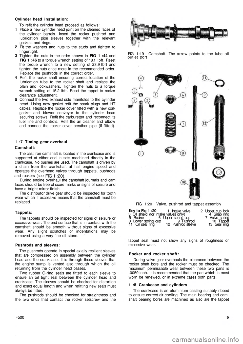
and rockers (see
FIG 1 :20).During engine overhaul the camshaft journals and cam
faces should be free of score marks or signs of seizure and
have a bright mirror finish.
The distributor drive gear should be inspected for tooth
wear which if excessive means that the camshaft must be
replaced.
Tappets:
The tappets should be inspected for signs of seizure or
excessive wear. The end surface that is in contact with the
camshaft should be smooth without signs of excessive
wear. Any slight scratches or indentations may be
removed using a very fine oil stone.
Pushrods and sleeves:
The pushrods operate in special axially resilient sleeves
that are compressed on assembly between the cylinder
head and the crankcase. It is through these sleeves that
the engine sump is vented also through which the oil
returning from the cylinder head passes.
Two rubber O-ring seals are fitted to each sleeve to
ensure an oil t i g h t seal between the cylinder head and
crankcase. The sleeves should be checked for distortion
and exact equal length and when refitting new seals must
always be fitted.
The pushrods should be checked for straightness and
the t w o ends that contact the rocker setscrew and the
F50019
The crankcase is an aluminium casting suitably ribbed
to ensure correct air cooling. The main bearing and cam-
shaft bearing bores are machined as also are the tappet 1 :8 Crankcase and cylinders During valve gear overhauls the clearance between the
rocker shaft bore and the rocker must be checked. The
maximum permissable wear between these t w o parts is
.0059 inch. It is recommended that the part which is most
worn be renewed, or in extreme cases both parts. Rocker and rocker shaft: tappet seat must not show any signs of roughness or
excessive wear. 3 Oil shield (for intake valves only) 4 Snap ring
5 Rocker 6 Upper spring cup 7 Valve spring
8 Lower spring cup 9 Pushrod 10 Tappet
11 Oil seal ring 12 Pushrod sleeve 13 Seal ring 1 Intake valve 2 Upper cup lock Key t o Fiq
1 :20 FIG 1:20 Valve, pushrod and tappet assembly FIG 1:19 Camshaft. The arrow points to the lube oil
outlet port
Page 24 of 128
sections of the air conveyor securing with seven
screws, seven toothed washers and five nuts.
22 Slide the fuel pump control rod into its seating,
assemble the insulator between oil wetted graphite
gaskets and fit the pump to the crankcase using nuts
and toothed washers.
23 Fit the air conveyor cover complete with the accelera-
tor control relay lever and rod. Secure using eight
mounting screws, eight toothed washers, eight plain
washers and eight nuts. Fit the fuel line retaining clip
which is secured by one of the air conveyor upper
screws. Install the generator and fan drive pulley
having first placed four adjusting rings between the
pulley halves and the thrust ring on the outside.
Secure the pulley to generator shaft using three
screws and three toothed washers. Fit the generator
fan drive belt.
24 Refit the carburetter having first positioned the
bakelite heat shield between the t w o oil moistened
graphite gaskets. Secure the carburetter using t w o
copper washers and t w o self-locking nuts. Fit the
exhaust silencer and secure to the exhaust manifolds
with nuts and spring washers. Place the t w o graphite
gaskets between the manifold joints. Fit both exhaust
silencer upper mounting brackets and secure them
on the top side to the brackets already in place w i t h
nuts and toothed washers on the bottom side w i t h
screws and toothed washers.
25 Carefully position the distributor at a 10 deg advance
setting and secure w i t h a
nut, plain washer and
spring washer. Fit the fuel pump to carburetter line
complete w i t h mounting bracket rubber lining and
secure the line with two clamps. If difficulty is
experienced in positioning the fuel line into the pump
or carburetter funnels it is suggested that the line
ends should be heated in hot water and thoroughly
dried before installing.
26 Install the air cleaner elbow and rubber hose assembly
on the top of the carburetter using a graphite gasket
in between and secure w i t h nuts, plain washers and
spring washers. Carefully position the air cleaner, line
and hose assembly and connect it to the elbow.
Secure the cleaner to air conveyor cover using screws
and toothed washers.
27 Fit the spark plug cables complete with the rubber
grommet for cable mounting bracket on engine
cowling and connect the cables to the distributor
and spark plugs. Fit the oil pressure gauge sender
unit together w i t h its sealing washer.
28 Install the cylinder head cover and oil breather pipe
assembly w i t h a cork gasket inserted between.
Secure w i t h self-locking nuts and fibre washers.
Connect the accelerator control relay lever rod to the
carburetter and secure with the clip.
29 Fill the oil pan with the correct grade and quantity of
oil, insert the dipstick and the engine is ready for
refitting.
1:18 Engine assembly (station wagon)
Reassembly of this engine is straightforward as it is
the reverse procedure to dismantling. It is recommended
that Sections 1 :5 and 1 :17 are studied as the assembly
technique is similar for both the horizontal and vertical
F50031 cylinder engines. The following points should however
be noted:
1 Refer to FIG 1 :45 for the correct positioning of the
connecting rod-piston assembly on the 120.000
engine.
2 The sequence of tightening the cylinder head nuts is
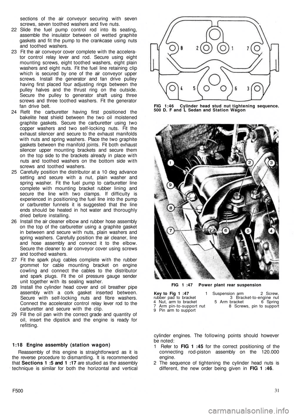
different, the new order being given in FIG 1 :46.
Key to Fig 1 :47 1 Suspension arm 2 Screw,
rubber pad to bracket 3 Bracket-to-engine nut
4 Nut, arm to bracket 5 Arm bracket 6 Spring
7 Arm pin-to-support nut 8 Screws, pin to support
9 Pin arm to supportFIG 1 :47 Power plant rear suspension FIG 1:46 Cylinder head stud nut tightening sequence.
500 D. F and L Sedan and Station Wagon
Page 28 of 128
CHAPTER 2
THE FUEL SYSTEM
2:1 Description
2 : 2 Fuel pump operating principles
2 : 3 Routine maintenance
2 : 4 Pump removal, dismantling and examination
2 : 5 Reassembly, installation and adjustment
2 : 6 Carburetter operation and adjustment,
Weber 26.1MB2 : 7 Modifications
2 : 8 Carburetter operation and adjustment,
Weber 26.OC
2 :9 Air cleaner
2 : 1 0 B l o w - b y gases recirculation device
2:11 Fuel tank
2:12 Fault diagnosis
2:1 Description
All the new 500 models use a mechanical diaphragm
fuel feed pump as shown in FIG 2 : 1. Four types of
carburetter are fitted depending on the model to which
the engine is installed. Each carburetter operation and
adjustment is fully described, together with details of the
recirculation device for blow-by gases and o i l vapours.
2 : 2 Fuel pump operating principles
Refer to FIG 2 : 2. An eccentric on the rotating camshaft
actuates the operating rocker 21 via a pushrod 25 which
depresses the diaphragm 14 and so creates a depression
in the pumping chamber located in upper body 5. Under
atmospheric pressure, petrol passes through the pipeline
connection and inlet valve into the pumping chamber.
The return spring 15 then raises the diaphragm, expelling
the petrol through the outlet valve and pipeline to the
carburetter float chamber.
When the float chamber is full, the pressure in the pipe-
line and pumping chamber holds the diaphragm depressed
against the tension of the return spring.2 : 3 Routine maintenance
A poor delivery of fuel to the carburetter may be due to
a fault in the fuel pump or related lines. Periodically the
pump body screws 19 (see FIG 2 : 2) and upper cover
screw 1 should be checked for tightness. The fuel pump
lines should be disconnected and checked for freedom of
restriction, chafing and loose connections. The fuel pump
filter should be removed and cleaned periodically.
2:4 Pump removal, dismantling and examination
The pump is located on the carburetter side of the
engine crankcase (sedan) or under the generator at the
front of the crankcase (station wagon).
Removal:
1 Disconnect the fuel pipe from the tank to stop petrol
syphoning out of the tank and then release the fuel
inlet and outlet pipes from the pump body.
2 Remove the t w o nuts and washers holding pump to
crankcase.
3 Carefully lift away the pump, gaskets and insulating pad
from the crankcase (see FIG 2 : 3).
F50035
Page 30 of 128
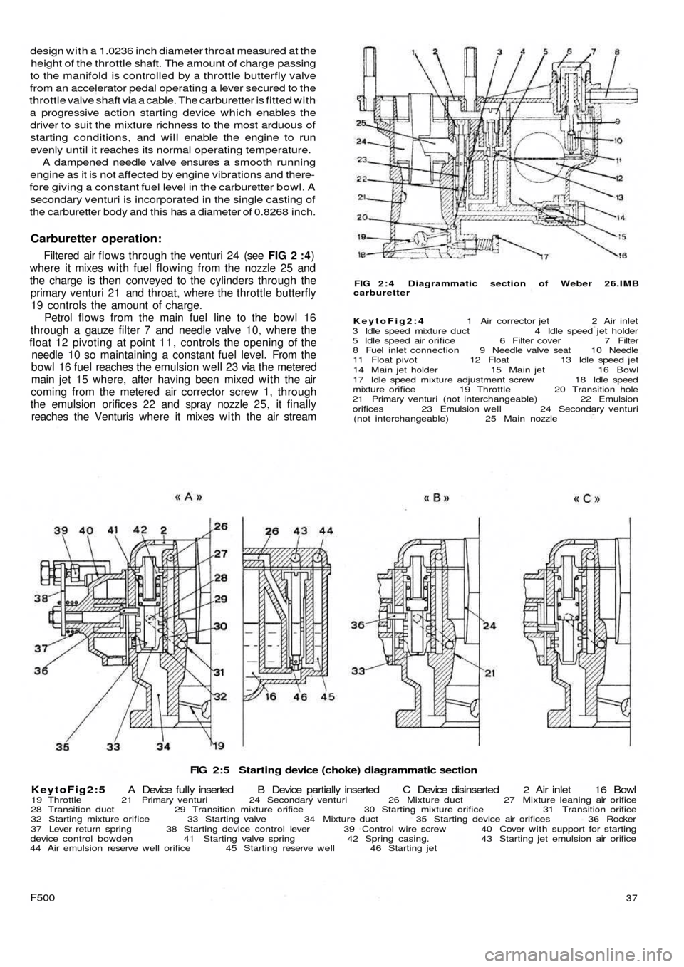
FIG 2:5 Starting device (choke) diagrammatic section
KeytoFig2:5 A Device fully inserted B Device partially inserted C Device disinserted 2 Air inlet 16 Bowl
19 Throttle 21 Primary venturi 24 Secondary venturi 26 Mixture duct 27 Mixture leaning air orifice
28 Transition duct 29 Transition mixture orifice 30 Starting mixture orifice 31 Transition orifice
32 Starting mixture orifice 33 Starting valve 34 Mixture duct 35 Starting device air orifices 36 Rocker
37 Lever return spring 38 Starting device control lever 39 Control wire screw 40 Cover with support for starting
device control bowden 41 Starting valve spring 42 Spring casing. 43 Starting jet emulsion air orifice
44 Air emulsion reserve well orifice 45 Starting reserve well 46 Starting jet
F50037
FIG 2 : 4 Diagrammatic section of Weber 26.IMB
carburetter
KeytoFig2:4 1 Air corrector jet 2 Air inlet
3 Idle speed mixture duct 4 Idle speed jet holder
5 Idle speed air orifice 6 Filter cover 7 Filter
8 Fuel inlet connection 9 Needle valve seat 10 Needle
11 Float pivot 12 Float 13 Idle speed jet
14 Main jet holder 15 Main jet 16 Bowl
17 Idle speed mixture adjustment screw 18 Idle speed
mixture orifice 19 Throttle 20 Transition hole
21 Primary venturi (not interchangeable) 22 Emulsion
orifices 23 Emulsion well 24 Secondary venturi
(not interchangeable) 25 Main nozzle
design with a 1.0236 inch diameter throat measured at the
height of the throttle shaft. The amount of charge passing
to the manifold is controlled by a throttle butterfly valve
from an accelerator pedal operating a lever secured to the
throttle valve shaft via a cable. The carburetter is fitted with
a progressive action starting device which enables the
driver to suit the mixture richness to the most arduous of
starting conditions, and will enable the engine to run
evenly until it reaches its normal operating temperature.
A dampened needle valve ensures a smooth running
engine as it is not affected by engine vibrations and there-
fore giving a constant fuel level in the carburetter bowl. A
secondary venturi is incorporated in the single casting of
the carburetter body and this has a diameter of 0.8268 inch.
Carburetter operation:
Filtered air flows through the venturi 24 (see FIG 2 :4)
where it mixes w i t h fuel flowing from the nozzle 25 and
the charge is then conveyed to the cylinders through the
primary venturi 21 and throat, where the throttle butterfly
19 controls the amount of charge.
Petrol flows from the main fuel line to the bowl 16
through a gauze filter 7 and needle valve 10, where the
float 12 pivoting at point 1 1 , controls the opening of the
needle 10 so maintaining a constant fuel level. From the
bowl 16 fuel reaches the emulsion well 23 via the metered
main jet 15 where, after having been mixed with the air
coming from the metered air corrector screw 1, through
the emulsion orifices 22 and spray nozzle 25, it finally
reaches the Venturis where it mixes w i t h the air stream
Page 38 of 128
Air cleaner—station wagon:
A pleated paper air cleaner element is housed in a
special air intake chamber connected to the front of the
engine air cooling cowling (see FIG 4 : 2) . This chamber
will be seen located towards the rear of t h e power unit
compartment. Remove the retaining wing nut, lift off the
lid and the element can be withdrawn by lifting upwards.
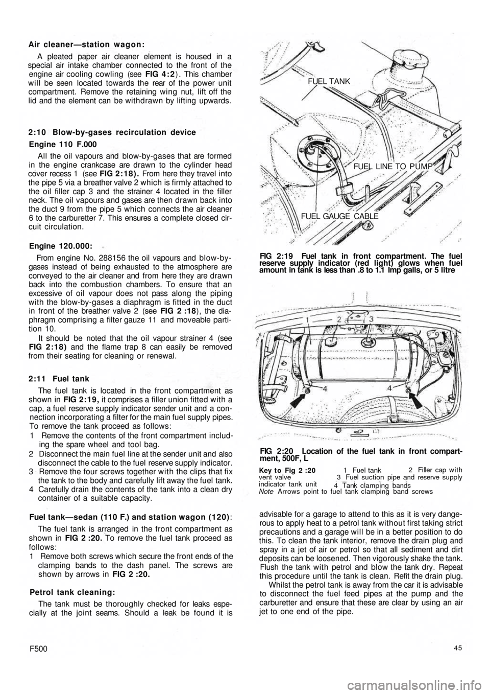
2:10 Blow-by-gases recirculation device
Engine 110 F.000
All the oil vapours and blow-by-gases that are formed
in the engine crankcase are drawn to the cylinder head
cover recess 1 (see FIG 2:18). From here they travel into
the pipe 5 via a breather valve 2 which is firmly attached to
the oil filler cap 3 and the strainer 4 located in the filler
neck. The oil vapours and gases are then d r a w n back into
the duct 9 from the pipe 5 which connects the air cleaner
6 to the carburetter 7. This ensures a complete closed cir-
cuit circulation.
Engine 120.000:
From engine No. 288156 the oil vapours and blow-by-
gases instead of being exhausted to the atmosphere are
conveyed to the air cleaner and from here they are drawn
back into the combustion chambers. To ensure that an
excessive of oil vapour does not pass along the piping
with the blow-by-gases a diaphragm is fitted in the duct
in front of the breather valve 2 (see FIG 2 :18), the dia-
phragm comprising a filter gauze 11 and moveable parti-
tion 10.
It should be noted that the oil vapour strainer 4 (see
FIG 2:18) and the flame trap 8 can easily be removed
from their seating for cleaning or renewal.
2 : 1 1 Fuel tank
The fuel tank is located in the front compartment as
shown in FIG 2:19, it comprises a filler union fitted with a
cap, a fuel reserve supply indicator sender unit and a con-
nection incorporating a filter for the main fuel supply pipes.
To remove the tank proceed as follows:
1 Remove the contents of the front compartment includ-
ing the spare wheel and tool bag.
2 Disconnect the main fuel line at the sender unit and also
disconnect the cable to the fuel reserve supply indicator.
3 Remove the four screws together w i t h the clips that fix
the tank to the body and carefully lift away the fuel tank.
4 Carefully drain the contents of the tank into a clean dry
container of a suitable capacity.
Fuel tank—sedan (110 F.) and station wagon (120):
The fuel tank is arranged in the front compartment as
shown in FIG 2 :20. To remove the fuel tank proceed as
follows:
1 Remove both screws which secure the front ends of the
clamping bands to the dash panel. The screws are
shown by arrows in FIG 2 :20.
Petrol tank cleaning:
The tank must be thoroughly checked for leaks espe-
cially at the joint seams. Should a leak be found it is
F50045
advisable for a garage to attend to this as it is very dange-
rous to apply heat to a petrol tank without first taking strict
precautions and a garage will be in a better position to do
this. To clean the tank interior, remove the drain plug and
spray in a jet of air or petrol so that all sediment and dirt
deposits can be loosened. Then vigorously shake the tank.
Flush the tank w i t h petrol and blow the tank dry. Repeat
this procedure until the tank is clean. Refit the drain plug.
Whilst the petrol tank is away from the car it is advisable
to disconnect the fuel feed pipes at the pump and the
carburetter and ensure that these are clear by using an air
jet to one end of the pipe.
Key t o Fig 2 :20
Note Arrows point to fuel tank clamping band screws vent valve
indicator tank unit1 Fuel tank2 Filler cap with
3 Fuel suction pipe and reserve supply
4 Tank clamping bands
FIG 2:20 Location of the fuel tank in front compart-
ment, 500F, L FIG 2:19 Fuel tank in front compartment. The fuel
reserve supply indicator (red light) glows when fuel
amount in tank is less than .8 to 1.1 Imp galls, or 5 litre FUEL TANK
FUEL LINE TO PUMP
FUEL GAUGE CABLE
Page 39 of 128
2:12 Fault diagnosis
(a) Leakage or insufficient fuel delivered
1 Air vent in tank restricted
2 Petrol pipes blocked
3 Air leaks at pipe connections
4 Pump or carburetter filters blocked
5 Pump gaskets faulty
6 Pump diaphragm defective
7 Pump valves sticking or seating badly
8 Fuel vapourizing in pipelines due to heat
(b) Excessive fuel consumption
1 Carburetter needs adjusting
2 Fuel leakage
3 Sticking controls or choke device
4 Dirty air cleaner
5 Excessive engine temperature
6 Brakes binding
7 Tyres under-inflated
8 Idling speed too high
9 Car overloaded(c) Idling speed too high
1 Rich fuel mixture
2 Carburetter controls sticking
3 Slow-running screws incorrectly adjusted
4 Worn carburetter butterfly valve
(d) Noisy fuel pump
1 Loose mountings
2 Air leaks on suction side and at diaphragm
3 Obstruction in fuel pipe
4 Clogged pump filter
(e) No fuel delivery
1 Float needle stuck
2 Vent in tank blocked
3 Pipeline obstructed
4 Pump diaphragm stiff or damaged
5 Inlet valve in pump stuck open
6 Bad air leak on suction side of pump
46
Page 102 of 128
10:9 Brake fluid reservoir
The reservoir is located in the front compartment to the
side of the fuel tank as shown in FIG 10:9. Should it be
necessary to detach the fluid outlet line from the reservoir
the outlet hole must be blanked off using a tapered
wooden peg of suitable length so that the cap may be
replaced to prevent the ingress of foreign matter into
the reservoir and the absorbtion of moisture, oil or petrol
vapours which would alter the properties of the hydraulic
fluid.
A special filter is fitted into the top of the reservoir
through which all fluid used for topping-up the reservoir
must pass to ensure utmost inner cleanliness of the
hydraulic system.
10:10 Bleeding the system
This is not a routine maintenance operation and is only
necessary if air has entered the hydraulic system because
parts have been dismantled or because the f l u i d level in
the reservoir has dropped so low that air has been drawn
into the main feed pipe to the master cylinders.
1 Fill the reservoir w i t h Fiat 'Blue Label' hydraulic fluid.
During the bleeding operation fluid will be used and
constant topping-up of the supply reservoir will be
needed. If this is not done it is possible for air to enter
the master cylinder main feed pipe which will nullify
the operation and necessitate a fresh start.
2 Attach a length of rubber or plastic tubing to the
bleeder screw on the rear wheel cylinder furthermost
from the master cylinder. Immerse the free end of the
tube in a small volume of hydraulic brake fluid in a
clean jar.
3 Open the bleed screw one turn and get a second
operator to press down slowly on the brake pedal. After
a full stroke let the pedal return without assistance,
pause a moment and repeat the d o w n stroke. At first
there will be air bubbles issuing from the bleed tube,
but when fluid alone is ejected, hold the pedal firmly
down on the floor panel and tighten the bleed screw.
Repeat this operation on the other rear brake and then
repeat the operation on the two front brakes.
4 On completion, top-up the fluid in the reservoir to the
correct level. Discard all dirty fluid. If fluid is perfectly
clean, let it stand for twenty four hours to become
clear of air bubbles before using it again.
10:11 Hand parking brake
Normally with the new 500 Sedan model automatic
brake adjusting device, adjustment of the rear brakes
will take up excessive handbrake travel.
If there is excessive travel on the handbrake of the
Sedan model at any time, or in the case of Station Wagon
model even after the rear brakes have been manually
adjusted, suspect worn brake shoe linings or stretched
handbrake cables. Examine the linings and fit replace-
ment shoes if necessary. Check the action of the hand
parking brake again and if there is still too much travel
before the brakes are applied it is permissible to take up as
follows:
1 It is essential to ensure that the rear shoes are correctly
adjusted as described in Section 10:2.
2 Apply the hand parking brake lever until the pawl
engages with the ratchet at the second notch.
F500
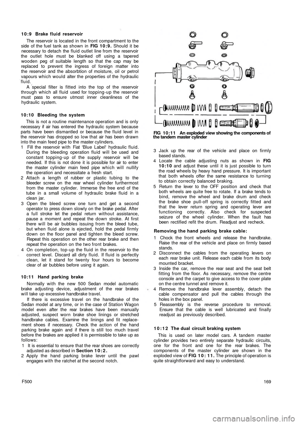
FIG 10:11 An exploded view showing the components of
the tandem master cylinder
3 Jack up the rear of t h e vehicle and place on firmly
based stands.
4 Locate the cable adjusting nuts as shown in FIG
10:10 and adjust these until it is just possible to turn
the road wheels by heavy hand pressure. It is important
that both wheels offer the same resistance to turning
to obtain correctly balanced braking.
5 Return the lever to the OFF position and check that
both wheels are quite free to rotate. If a brake tends to
bind, remove the wheel and brake drum and check
the brake shoe pull-off spring is correctly fitted and
that the lever return spring and operating lever are
functioning correctly. Also check for suspected
seizure of the wheel cylinder. When the fault has
been rectified refit the drum. Readjust and recheck.
Removing the hand parking brake cable:
1 Chock the front wheels and release the handbrake.
Raise t h e rear of the vehicle and place on firmly based
stands.
2 Disconnect the cables from the operating levers on
each rear brake unit. Release each cable from its body
mounted bracket.
3 Inside the car, remove the rear seat and the seat belt
fitting from the floor. As necessary, remove the centre
console and the carpet to give access to the cover plate
on the centre tunnel and remove it.
4 Remove the handbrake lever assembly, detach the
cable compensator and pull the cables through the
holes in the box panel.
5 Reassembly is the reverse procedure to removal.
Ensure t h a t the cable is well lubricated and finally
readjust as previously described.
10:12 The dual circuit braking system
This is used on later model cars. A tandem master
cylinder provides t w o entirely separate hydraulic circuits,
one for the front and one for the rear brakes. The
components of the master cylinder are shown in the
exploded view of FIG 1 0 : 1 1 . The principle of operation is
quite straightforward and easy to understand.
169