air condition FIAT 500 1969 1.G Workshop Manual
[x] Cancel search | Manufacturer: FIAT, Model Year: 1969, Model line: 500, Model: FIAT 500 1969 1.GPages: 128, PDF Size: 9.01 MB
Page 25 of 128
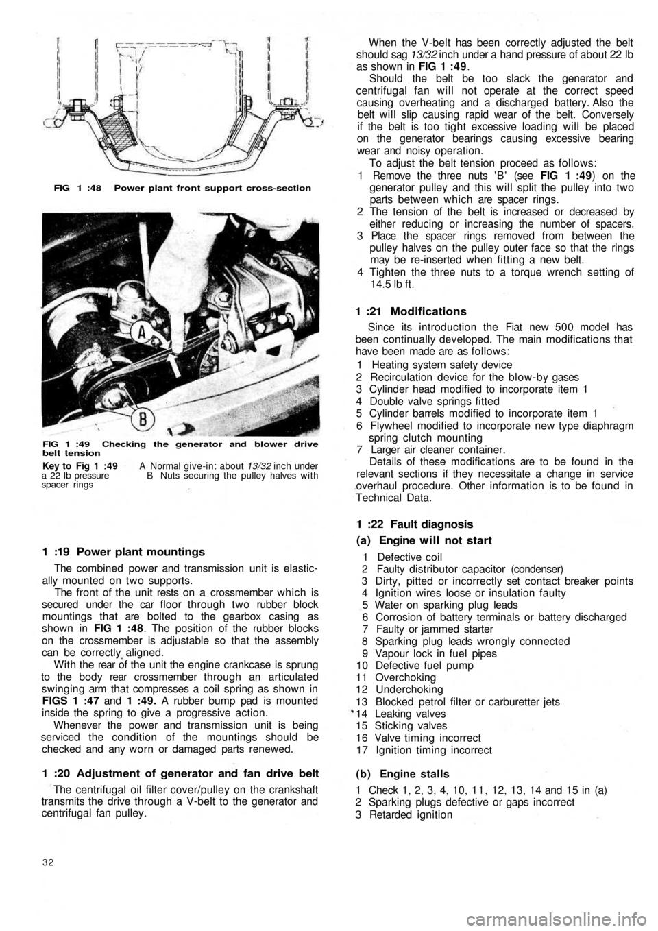
FIG 1 :48 Power plant front support cross-section
FIG 1 :49 Checking the generator and blower drive
belt tension
1 :19 Power plant mountings
The combined power and transmission unit is elastic-
ally mounted on two supports.
The front of the unit rests on a crossmember which is
secured under the car floor through two rubber block
mountings that are bolted to the gearbox casing as
shown in FIG 1 :48. The position of the rubber blocks
on the crossmember is adjustable so that the assembly
can be correctly aligned.
W i t h t h e rear of the unit the engine crankcase is sprung
to the b o d y rear crossmember through an articulated
swinging arm that compresses a coil spring as shown in
FIGS 1 :47 and 1 :49. A rubber bump pad is mounted
inside the spring to give a progressive action.
Whenever the power and transmission unit is being
serviced the condition of the mountings should be
checked and any worn or damaged parts renewed.
1 :20 Adjustment of generator and fan drive belt
The centrifugal oil filter cover/pulley on the crankshaft
transmits the drive through a V-belt to the generator and
centrifugal fan pulley.
32
(b) Engine stalls
1 Check 1, 2, 3, 4, 10, 1 1 , 12, 13, 14 and 15 in (a)
2 Sparking plugs defective or gaps incorrect
3 Retarded ignition 1 Defective coil
2 Faulty distributor capacitor (condenser)
3 Dirty, pitted or incorrectly set contact breaker points
4 Ignition wires loose or insulation faulty
5 Water on sparking plug leads
6 Corrosion of battery terminals or battery discharged
7 Faulty or jammed starter
8 Sparking plug leads wrongly connected
9 Vapour lock in fuel pipes
10 Defective fuel pump
11 Overchoking
12 Underchoking
13 Blocked petrol filter or carburetter jets
14 Leaking valves
15 Sticking valves
16 Valve timing incorrect
17 Ignition timing incorrect
(a) Engine will not start 1 :22 Fault diagnosis
Since its introduction the Fiat new 5 0 0 model has
been continually developed. The main modifications that
have been made are as follows:
1 Heating system safety device
2 Recirculation device for the blow-by gases
3 Cylinder head modified to incorporate item 1
4 Double valve springs fitted
5 Cylinder barrels modified to incorporate item 1
6 Flywheel modified to incorporate new type diaphragm
spring clutch mounting
7 Larger air cleaner container.
Details of these modifications are to be found in the
relevant sections if they necessitate a change in service
overhaul procedure. Other information is to be found in
Technical Data.
1 :21 Modifications
When the V-belt has been correctly adjusted the belt
should sag 13/32 inch under a hand pressure of about 22 lb
as shown in FIG 1 : 4 9.
Should the belt be too slack the generator and
centrifugal fan will not operate at the correct speed
causing overheating and a discharged battery. Also the
belt will slip causing rapid wear of the belt. Conversely
if the belt is too tight excessive loading will be placed
on the generator bearings causing excessive bearing
wear and noisy operation.
To adjust the belt tension proceed as follows:
1 Remove the three nuts ' B ' (see FIG 1 :49) on the
generator pulley and this will split the pulley into two
parts between which are spacer rings.
2 The tension of the belt is increased or decreased by
either reducing or increasing the number of spacers.
3 Place the spacer rings removed from between the
pulley halves on the pulley outer face so that the rings
may be re-inserted when fitting a new belt.
4 Tighten the three nuts to a torque wrench setting of
14.5
lb ft.
Key to Fig 1 :49 A Normal give-in: about 13/32 inch under
a 22 Ib pressure B Nuts securing the pulley halves with
spacer rings
Page 30 of 128
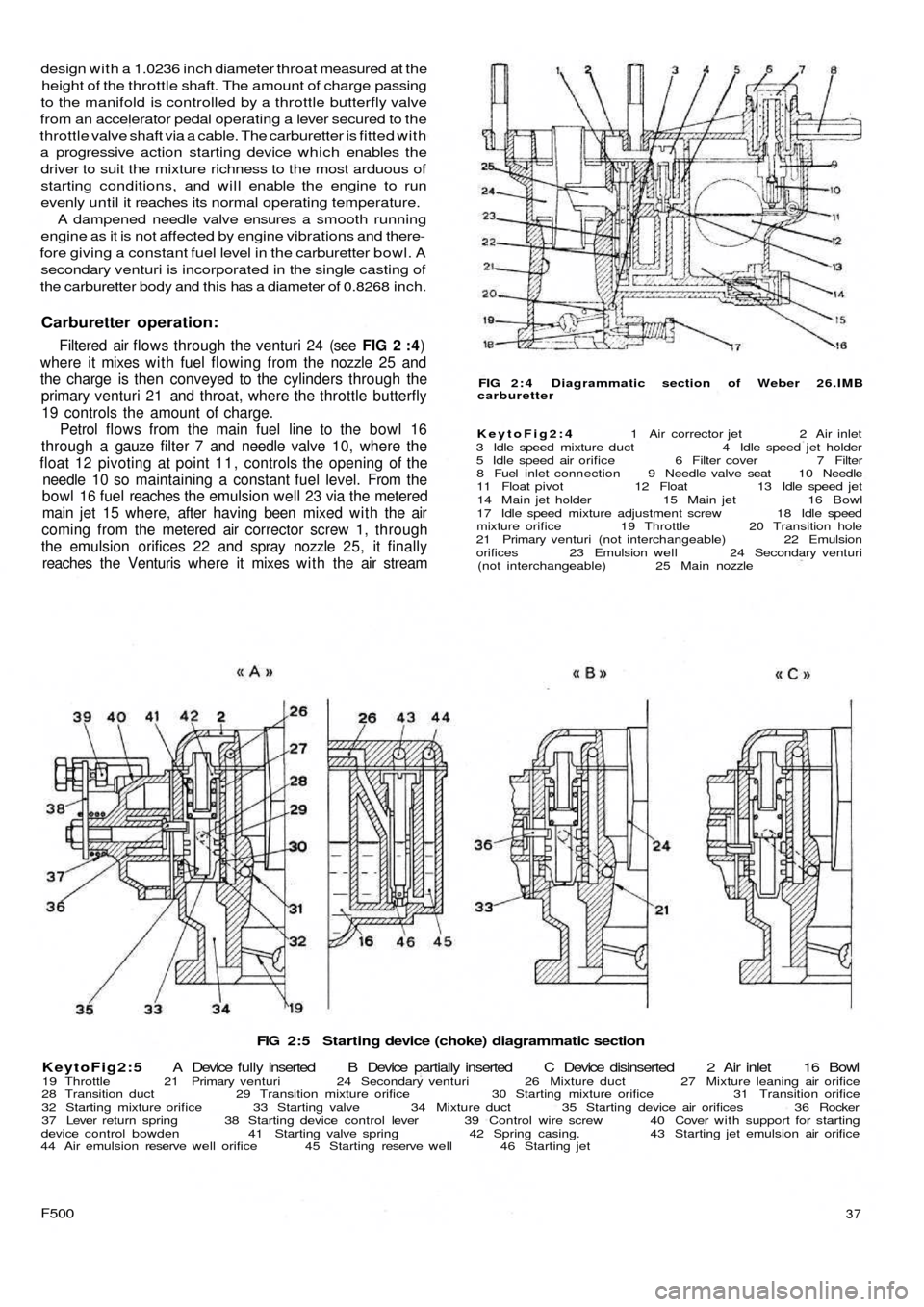
FIG 2:5 Starting device (choke) diagrammatic section
KeytoFig2:5 A Device fully inserted B Device partially inserted C Device disinserted 2 Air inlet 16 Bowl
19 Throttle 21 Primary venturi 24 Secondary venturi 26 Mixture duct 27 Mixture leaning air orifice
28 Transition duct 29 Transition mixture orifice 30 Starting mixture orifice 31 Transition orifice
32 Starting mixture orifice 33 Starting valve 34 Mixture duct 35 Starting device air orifices 36 Rocker
37 Lever return spring 38 Starting device control lever 39 Control wire screw 40 Cover with support for starting
device control bowden 41 Starting valve spring 42 Spring casing. 43 Starting jet emulsion air orifice
44 Air emulsion reserve well orifice 45 Starting reserve well 46 Starting jet
F50037
FIG 2 : 4 Diagrammatic section of Weber 26.IMB
carburetter
KeytoFig2:4 1 Air corrector jet 2 Air inlet
3 Idle speed mixture duct 4 Idle speed jet holder
5 Idle speed air orifice 6 Filter cover 7 Filter
8 Fuel inlet connection 9 Needle valve seat 10 Needle
11 Float pivot 12 Float 13 Idle speed jet
14 Main jet holder 15 Main jet 16 Bowl
17 Idle speed mixture adjustment screw 18 Idle speed
mixture orifice 19 Throttle 20 Transition hole
21 Primary venturi (not interchangeable) 22 Emulsion
orifices 23 Emulsion well 24 Secondary venturi
(not interchangeable) 25 Main nozzle
design with a 1.0236 inch diameter throat measured at the
height of the throttle shaft. The amount of charge passing
to the manifold is controlled by a throttle butterfly valve
from an accelerator pedal operating a lever secured to the
throttle valve shaft via a cable. The carburetter is fitted with
a progressive action starting device which enables the
driver to suit the mixture richness to the most arduous of
starting conditions, and will enable the engine to run
evenly until it reaches its normal operating temperature.
A dampened needle valve ensures a smooth running
engine as it is not affected by engine vibrations and there-
fore giving a constant fuel level in the carburetter bowl. A
secondary venturi is incorporated in the single casting of
the carburetter body and this has a diameter of 0.8268 inch.
Carburetter operation:
Filtered air flows through the venturi 24 (see FIG 2 :4)
where it mixes w i t h fuel flowing from the nozzle 25 and
the charge is then conveyed to the cylinders through the
primary venturi 21 and throat, where the throttle butterfly
19 controls the amount of charge.
Petrol flows from the main fuel line to the bowl 16
through a gauze filter 7 and needle valve 10, where the
float 12 pivoting at point 1 1 , controls the opening of the
needle 10 so maintaining a constant fuel level. From the
bowl 16 fuel reaches the emulsion well 23 via the metered
main jet 15 where, after having been mixed with the air
coming from the metered air corrector screw 1, through
the emulsion orifices 22 and spray nozzle 25, it finally
reaches the Venturis where it mixes w i t h the air stream
Page 31 of 128
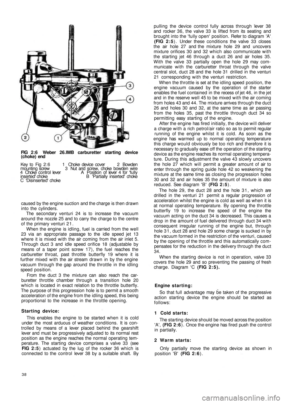
FIG 2 : 6 Weber 26.IMB carburetter starting device
(choke) end
Key to Fig 2 : 6 1 Choke device cover 2 Bowden
mounting screw 3 Nut and screw, choke bowden wire
4 Choke control lever A Position of lever 4 for 'fully
inserted' choke B 'Partially inserted' choke
C 'Disinserted' choke
caused by the engine suction and the charge is then drawn
into the cylinders.
The secondary venturi 24 is to increase the vacuum
around the nozzle 25 and to carry the charge to the centre
of the primary venturi 2 1 .
When the engine is idling, fuel is carried from the well
23 via an appropriate passage to the idle speed jet 13
where it is mixed with the air coming from the air inlet 5.
Through duct 3 and idle speed orifice 18 (adjustable by
means of a taper point screw 17), the fuel reaches the
carburetter throat, past throttle butterfly 19 where it is
further mixed with the air stream drawn in by the engine
vacuum through the gap around the throttle in the idling
speed position.
From the d u c t 3 the mixture can also reach the car-
buretter throttle chamber through a transition hole 20
which is located in exact relation to the throttle butterfly.
The purpose of this progression hole is to permit a smooth
acceleration of the engine from the idling speed, this being
proportional to the increase in the throttle opening.
Starting device:
This enables the engine to be started when it is cold
under the most arduous of weather conditions. It is con-
trolled by means of a lever placed behind the gearshift
lever and must be progressively adjusted to its normal
rest
position as the engine reaches the normal operating tem-
perature. The starting device comprises a valve 33 (see
FIG 2 : 5) actuated by the lug of the rocker 36 which is
connected to the control lever 38 by a suitable shaft. By
38
pulling the device control fully across through lever 38
and rocker 36, the valve 33 is lifted from its seating and
brought into the 'fully open' position. Refer to diagram 'A'
(FIG 2 : 5) . Under these conditions the valve 33 closes
the air hole 27 and the mixture hole 29 and uncovers
mixture orifices 30 and 32 which also communicate with
the starting jet 46 through a duct 26 and air holes 35.
With the valve 33 partially open the hole 29 may com-
municate with the carburetter throat through the valve
central slot, duct 28 and the hole 31 drilled in the venturi
21 corresponding with the venturi restriction.
When the throttle is set at the idling speed position, the
engine vacuum caused by the operation of the starter
enables the fuel contained in the recess of jet 4 6 , in the jet
and in the reserve well 45 to be mixed w i t h the air coming
from holes 43 and 44. The mixture arrives through the duct
26 and holes 30 and 32, at the same time as air passing
from the holes 35, past the throttle through duct 34 so
permitting easy starting of the engine.
After the engine has fired initially, the device will deliver
a charge with a rich petrol/air ratio so as to permit regular
running of the engine whilst it is cold. As soon as the
engine has warmed up to normal operating temperature
this charge would obviously be too rich and therefore it is
necessary to gradually ease o f f the operation of the starting
device as the engine reaches its normal operating tempera-
ture. During this adjustment the valve 43 slowly uncovers
the hole 27 which will permit a greater amount of air to
enter through the spring guide hole 42 so weakening the
mixture at the same time as closing the progression holes
30 and 32 and air holes 35 the amount of mixture is also
reduced. See diagram ' B ' (FIG 2 : 5).
The hole 29, the duct 28 and the hole 3 1 , which are
drilled in the venturi 21 permit a regular progression of
acceleration whilst the engine is cold as well as when it is
at normal operating temperature. By opening the throttle
butterfly 19 to increase the speed of the engine the
vacuum acting on the duct 34 is decreased. This causes a
drop in the amount of fuel delivered through duct 34 with
consequent irregular running of the engine but, through
hole 3 1 , duct 28 and hole 29 some charge is sucked in by
the vacuum formed in the restriction of the venturi, caused
by the opening of the throttle and this automatically com-
pensates for the reduction in the delivery through the duct
34.
When the starting device is not in operation, valve 33
covers the hole 29 and so preventing the passing of fresh
charge. Diagram ' C (FIG 2:5).
Engine s t a rting:
So that full advantage may be taken of the progressive
action starting device the engine should be started as
follows:
1 Cold starts:
The starting device should be moved across the position
'A', (FIG 2 : 6) . Once the engine has fired push the control
in partially.
2 Warm starts:
Only partially move the starting device as shown in
position 'B' (FIG 2 : 6).
Page 33 of 128
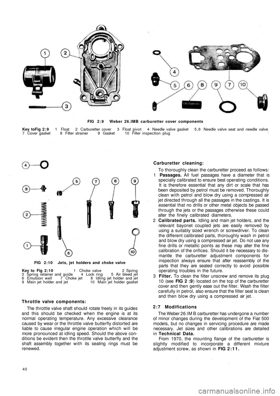
FIG 2 : 9 Weber 26.IMB carburetter cover components
Key toFig 2 : 9 1 Float 2 Carburetter cover 3 Float pivot 4 Needle valve gasket 5 , 6 Needle valve seat and needle valve
7 Cover gasket 8 Filter strainer 9 Gasket 10 Filter inspection plug
Carburetter cleaning:
To thoroughly clean the carburetter proceed as follows:
1 Passages. All fuel passages have a diameter that is
specially calibrated to ensure best operating conditions.
It is therefore essential that any dirt or scale that has
been deposited by petrol must be removed. Thoroughly
clean with petrol and blow dry using a compressed air
jet directed through all the passages in the castings. It is
essential that no drills or other metal objects be passed
through the jets or the passages otherwise these could
alter the finely calibrated diameters.
2 Calibrated parts. Idling and main jet holders, and the
relevant bayonet coupled jets are easily removed by
using a suitably sized wrench or screwdriver. To clean
the different calibrated parts, thoroughly wash in petrol
and blow dry using a compressed air jet. Do not use any
fine drills or metallic points as these may alter the fine
calibration of the orifices. Should it be necessary to dis-
mantle the carburetter adjustment components for
inspection always ensure that after reassembly of the
parts that they are seated correctly to avoid possible
operating troubles in the future.
3 Filter. To clean the filter unscrew and remove its plug
10 (see FIG 2 : 9) located on the top of the carburetter
cover and then gently ease o u t t h e filter. Wash the filter
carefully in petrol, also ensure that the filter seat is clean
and then blow dry using a compressed air jet.
2:7 Modifications
The Weber 26.IM B carburetter has undergone a number
of minor changes during the development of the Fiat 500
models, but no changes in servicing procedure are made
necessary. Jet sizes and other calibrations are detailed
in Technical Data.
From 1970, the mounting flange of the carburetter is
slightly modified to incorporate a different mixture
adjustment screw, as shown in FIG 2:11.
40
Throttle valve components:
The throttle valve shaft should rotate freely in its guides
and this should be checked when the engine is at its
normal operating temperature. Any excessive clearance
caused by wear or the throttle valve butterfly distorted are
liable to cause irregular engine operation which will be
more pronounced at idling speed. Should the above con-
ditions be evident then the throttle valve butterfly and the
shaft assembly together with its sealing rings must be
renewed.
FIG 2:10 Jets, jet holders and choke valve
Key to Fig 2:10 1 Choke valve 2 Spring
3 Spring retainer and guide 4 Lock ring 5 Air bleed jet
6 Emulsion well 7 Choke jet 8 Idling jet holder and jet
9 Main jet holder and jet 10 Main jet holder gasket
Page 34 of 128
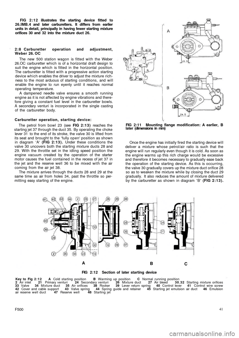
FIG 2:12 illustrates the starting device fitted to
26.IMB.4 and later carburetters. It differs from earlier
units in detail, principally in having fewer starting mixture
orifices 30 and 32 into the mixture duct 26.
2 : 8 Carburetter operation and adjustment,
Weber 26. OC
The new 500 station wagon is fitted with the Weber
26.OC carburetter which is of a horizontal draft design to
suit the engine which is fitted in the horizontal position.
The carburetter is fitted with a progressive action starting
device which enables the driver to adjust the mixture rich-
ness to the most arduous of starting conditions, and will
enable the engine to run eyenly until it reaches normal
operating temperature.
A dampened needle valve ensures a smooth running
engine as it is not affected by engine vibrations and there-
fore giving a constant fuel level in the carburetter bowls.
A secondary venturi is incorporated in the single casting
of the carburetter body.
Carburetter operation, starting device:
The petrol from bowl 23 (see FIG 2:13) reaches the
starting jet 37 through the duct 35. By operating the choke
lever 31 to the end of its stroke, the valve 30 is lifted from
its seat and brought to the 'fully open' position as shown
in diagram 'A' (FIG 2:13). Under these conditions the
valve 30 uncovers both the starting mixture ducts 28 and
29. With the throttle set in the idling speed position the
engine vacuum created by the operation of the starter
motor causes the fuel contained in the recess of j e t 37 in
the jet and the reserve
well 36 to be mixed with the air
coming from the air jet 38.
The mixture arrives through the ducts 28 and 29 at the
same time as air from holes 34, past the throttle so per-
mitting easy starting of the engine.
A
B
C
FIG 2:12 Section of later starting device
Key to Fig 2:12 A Cold starting position B Warming up position C Normal running position
2 Air inlet 21 Primary venturi 24 Secondary venturi 26 Mixture duct 27 Air bleed 30,32 Starting mixture orifices
33 Valve 34 Mixture duct 35 Air orifices 38 Rocker 39 Lever return spring 40 Control lever 41 Control wire screw
42 Cover and cable support 43 Valve spring 44 Spring guide and retainer 45 Starting jet emulsion air duct 46 Emulsion
air reserve well duct 47 Reserve well 48 Starting jet
F50041 Once the engine has initially fired the starting device will
deliver a mixture whose petrol/air ratio is such that the
engine will run regularly even though it is cold. As soon as
the engine warms up this rich charge would be excessive
and therefore it becomes necessary to gradually ease back
the operation of the starting device. As this is occurring,
the valve 30 gradually covers up the mixture duct orifice 28
so as to weaken the mixture while by closing the duct 29
gradually. It also reduces the amount of mixture delivered
by the carburetter as shown in diagram ' B ' (FIG 2:13). FIG 2:11 Mounting flange modification: A earlier, B
later (dimensions in mm)
Page 37 of 128
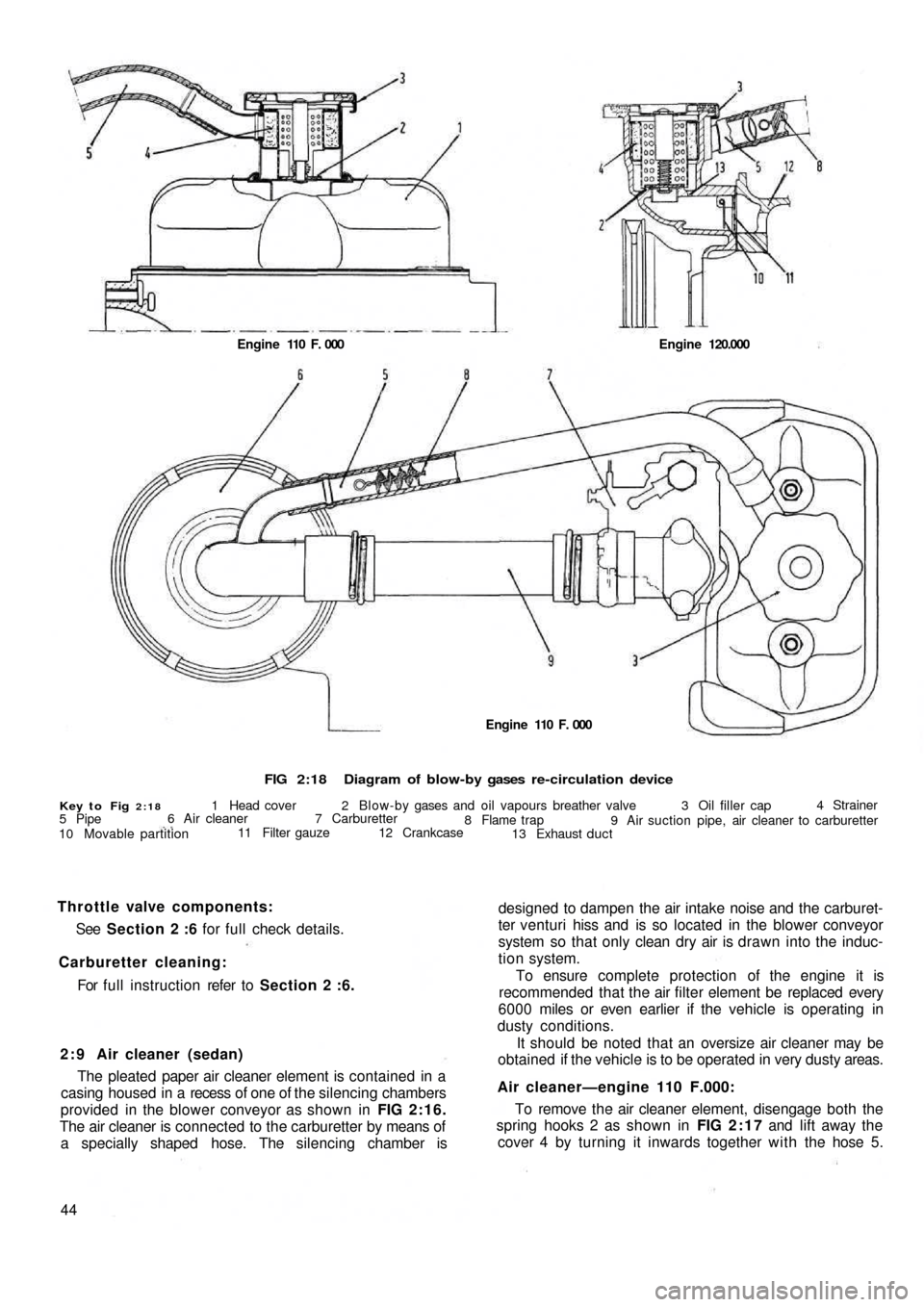
FIG 2:18Diagram of blow-by gases re-circulation device
Key to Fig 2:181 Head cover 2 Blow-by gases and oil vapours breather valve 3 Oil filler cap4 Strainer
9 Air suction pipe, air cleaner to carburetter 8 Flame trap
13 Exhaust duct 12 Crankcase 7 Carburetter 6 Air cleaner
11 Filter gauze
10 Movable partition 5 PipeEngine 110 F. 000 Engine 120.000
designed to dampen the air intake noise and the carburet-
ter venturi hiss and is so located in the blower conveyor
system so that only clean dry air is drawn into the induc-
tion system.
To ensure complete protection of the engine it is
recommended that the air filter element be replaced every
6000 miles or even earlier if the vehicle is operating in
dusty conditions.
It should be noted that an oversize air cleaner may be
obtained if the vehicle is to be operated in very dusty areas.
Air cleaner—engine 110 F.000:
To remove the air cleaner element, disengage both the
spring hooks 2 as shown in FIG 2:17 and lift away the
cover 4 by turning it inwards together with the hose 5. 2 : 9 Air cleaner (sedan)
The pleated paper air cleaner element is contained in a
casing housed in a recess of one of the silencing chambers
provided in the blower conveyor as shown in FIG 2:16.
The air cleaner is connected to the carburetter by means of
a specially shaped hose. The silencing chamber is
44For full instruction refer to Section 2 :6. Carburetter cleaning:See Section 2 :6 for full check details. Throttle valve components:
Engine 110 F. 000
Page 44 of 128
indicates the condition inside the combustion chamber
and may be used as a guide to engine tuning.
Before the spark plugs are removed b l o w away any
loose dirt from the plug recesses using a compressed air
jet or tyre pump. Store the plugs in the order of removal
ready for inspection.
Examine the gaskets and if they are about half their
thickness they may be used again otherwise they must be
replaced.
Inspect the electrode end of the plugs and note the
type and colour of the deposit. Normally it should be
powdery and range from b r o w n to a greyish tan in colour.
There will also be slight wear of the electrodes and the
general effect described is one which comes from mixed
periods of high-speed and low-speed driving. Cleaning
and resetting the gap is all that will be necessary.
If the deposits are white or yellowish they indicate long
periods of constant-speed driving or much low-speed
city driving. Again, the treatment is straightforward.
Dry, black, fluffy deposits are usually the result of
running with too rich a mixture. Incomplete combustion
of the petrol air charge may also be a cause and this might
be traced to a defect in the ignition system or excessive
idling.
Overheated sparking plugs have a white blistered look
about the centre electrode and the side electrode may be
badly eroded. This may be caused by poor cooling, wrong
ignition timing or sustained high speeds under heavy load.
To clean the sparking plugs effectively they should be
cleaned using an abrasive blasting machine and tested
under pressure once the electrodes have been reset. File
these until they are clean, bright and the faces parallel and
set the gap to .019 to .023 inch. Do not try to bend the
centre electrode.
Before replacing the plugs use a wire brush to clean the
threads taking care that the electrodes are not touched.
Thoroughly clean the spark plug in petrol, and dry using a
compressed air jet or a tyre pump. If difficulty is found in
screwing the plugs into the cylinder head by hand run a
tap d o w n the threads to clear away any carbon. If a tap is
not available use an old sparking plug with crosscuts d o w nthe threads. Finally tighten the plugs to a torque wrench
setting of 18 to 21 Ib ft.
Sparking plug leads:
The spark plug leads and the lead from the coil to the
distributor cap must be regularly checked for cracking of
the insulation and also correct seating in the distributor
cap and coil top. It is recommended that silicone grease is
smeared around the sockets before the leads are replaced
to ensure no moisture may enter causing difficult starting.
3 : 9 The distributor driving spindle (sedan and
sports engine)
If for any reason, the driving spindle has been removed
from its housing in the crankcase, it must be correctly
meshed w i t h the camshaft gear otherwise it
will be impos-
sible to set the ignition timing.
3:10 Fault diagnosis
(a) Engine w i l l not fire
1 Battery discharged
2 Distributor contact points dirty, pitted or maladjusted
3 Distributor cap dirty, cracked or tracking
4 Carbon brush inside distributor cap not touching rotor
5 Faulty cable or loose connection in low-tension circuit
6 Distributor rotor arm cracked
7 Faulty coil
8 Broken contact breaker spring
9 Contact points stuck open
(b) Engine misfires
1 Check 2, 3, 4, and 7 in (a)
2 Weak contact breaker spring
3 High-tension plug and coil leads cracked or perished
4 Sparking plug(s) loose
5 Sparking plug insulation cracked
6 Sparking plug gap incorrectly set
7 Ignition timing too far advanced
Page 50 of 128
4 : 4 Heating system safety device
110F series sedan engines and later station wagon
engines incorporate a modification to the cylinder head
designed so that in the event of cylinder head gasket
failure exhaust gases are expelled outside the engine and
not leaked into the heating system.
The safety device comprises a square section circular
seat 1 (see FIG 4 :6) which is formed in the upper face of
the cylinder, a special duct in the cylinder head and a
pierced screw 3 for each cylinder.
The system is so designed that the exhaust gases are
released to the atmosphere from the circular seat in the
cylinder via the duct 2 and the pierced screw 3. It should
be noted that the screw 3 is also used for securing the
conveyor.
4 : 5 Maintenance
Due to the simple design of the air cooling system
maintenance has been kept to an absolute minimum and
should consist of the following checks:1 Inspect all the air conveyor system joints and ensure
that all the joint nuts and bolts are tight and that there
is no distortion between two joint faces.
2 Check that the tension of the generator and fan drive
belt is correct: with a hand pressure of approximately
22 Ib the belt should sag 13/32 inch. Adjust if necessary
as detailed in Chapter 1.
3 Ensure that the shutter can swivel freely and that the
spring is in a serviceable condition.
4 : 6 Fault diagnosis
(a) Engine overheating
1 Generator and fan drive belt slipping
2 Shutter control thermostat defective
3 Shutter unable to swivel freely
4 Shutter return spring broken
5 Leaking joints in conveyor system
F50057
Page 62 of 128
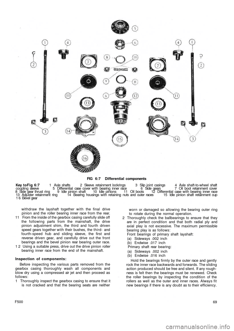
FIG 6:7 Differential components
Key toFig 6:7 1 Axle shafts 2 Sleeve retainment lockrings 3 Slip joint casings 4 Axle shaft-to-wheel shaft
coupling sleeve 5 Differential case cover w i t h bearing inner race 6 Side gears 7 Oil boot retainment cover
8 Side gear thrust ring 9 Idle pinion shaft 10 Idle pinions 11 Oil boots 12 Differential case w i t h bearing inner race
13 Adjuster retainment ring 14 Bearing housings with retaining nuts and outer races 15 Idle pinion shaft retainment cup
1 6 Bevel gear
withdraw the layshaft together w i t h the final drive
pinion and the roller bearing inner race from the rear.
11 From the inside of the gearbox casing carefully slide off
the following parts from the mainshaft, the drive
pinion adjustment shim, the third and fourth driven
speed gears together with their bushes, the t hird- and
fourth-speed hub and sliding sleeve, the first and
reverse driven gear, and carefully drive out the front
bearings and the bevel pinion rear bearing outer race.
1 2 Using a suitable press, drive out the drive pinion roller
bearing inner race from the end of the mainshaft.
Inspection of components:
Before inspecting the various parts removed from the
gearbox casing thoroughly wash all components and
blow dry using a compressed air jet and then proceed as
follows:
1 Thoroughly inspect the gearbox casing to ensure that it
is not cracked and that the bearing seats are neither
F50069 worn or damaged so allowing the bearing outer ring
to rotate during the normal operation.
2 Thoroughly check the ballbearings to ensure that they
are in perfect condition and that both radial ply and
axial play is not excessive. The maximum permissible
bearing play is as follows:
Front bearings of primary shaft layshaft:
(a) Sideways .002 inch
(b) Endwise .017 inch
Primary shaft rear bearing:
(a) Sideways .002 inch
(b) Endwise .016 inch
Hold the bearings firmly by the outer race and gently
rock the inner race backwards and forwards. The sliding
action produced should be free and silent. If any rough-
ness is felt then the bearings must be renewed. Check
the roller bearings by inspecting the condition of the
rollers as well as the outer and inner races. Always fit
new bearings if there is any doubt as to their efficiency.
Page 63 of 128
3 Check the layshaft and the primary shaft between
centres and using a dial gauge ensure that there is no
distortion. The out of true reading for bearing seats
should be less than .0008 inch. Inspect the splines and
ensure that the side and outerfaces are not indented.
Replace if there are signs of wear. Also inspect the
reverse shaft to ensure that it is perfectly smooth and
not showing signs of pitting or partial seizure.
4 Carefully inspect all gear teeth for signs of excessive
wear or damage. The contact faces must be smooth and
show no signs of indentation marks. Also check that
the backlash between the gears, when correctly
mounted on the surface plate is not greater than .0039
inch. The maximum wear limit is .0079 inch. Check that
the quick engagement front teeth of the second-, third-
and fourth-speed gears are not damaged or excessively
worn. Renew if there are signs of gearchange lever
misuse.
5 Inspect the sliding sleeves and the relevent hubs, ensure
that all the working surfaces are perfectly smooth. The
clearance between the mating parts should not be
greater than .0059 inch. Also inspect the meshing teeth
and ensure that they are in good condition.
6 Check that the gear shifting selector forks are not dis-
torted and that the striker rods freely slide in their seats
in the gearbox casing.
7 Carefully inspect that all the oil seals are in perfect con-
dition and if there is any doubt they should be renewed.
8 Inspect the striker rod locking balls and the safety rollers
and ensure that they slide freely in their seatings. Also
check the ball load spring efficiency and if this shows
signs of weakness then it should be renewed. Any
faults with these items will cause difficulty in engaging
gears or autodisengagement during engine acceleration.
6 : 4 Reassembly—gearbox
To reassemble the components to the gearbox ensure
that all components are thoroughly clean and then pro-
ceed as follows:
1 Press t h e pinion rear roller bearing onto the layshaft.
Install the layshaft in the casing, and at the same time
fit the adjustment shim, the fourth-speed driven gear
together w i t h its bush, the sleeve and hub for third and
fourth gear engagement, the first-speed and reverse
driven gear and the third-speed driven gear with its
hub.
2 Install the front layshaft ballbearing securing the
bearing retainment plate w i t h the screws and finally
lock the screws in position.
3 Insert the primary shaft together with the first, third
and fourth driving gear train in the gearbox housing
and slide t h e rear bearing onto the shaft. Push the
input shaft forward to enable the clutch shaft coupling
to be inserted in t h e rear and to be pulled up the
primary shaft by means of the pin. Do not forget the
retaining ring.
4 Slide the primary shaft backwards so pushing the rear
bearing into its bore. Refit the front bearing onto the
primary shaft.
5 On the layshaft insert the second-speed driven shaft
and bush, the second gear sliding dog sleeve and the
hub. Also insert the second-speed striker rod and the
first-speed fork. Do not forget to fit the safety roller
into its seating.
70
6 Slide the second-speed driving gear onto the primary
shaft. Place the engagement fork on the third- and
fourth-speed engagement sliding sleeve, and insert
the striker rod, lock the relevent fork and fit the safety
roller.
7 Insert the third safety roller and install the reverse shaft
and insert the reverse gear cluster onto it and secure
the shaft by tightening its block bolt. Install the reverse
striker rod w i t h its relevent fork.
8 Now refit the speedometer drive worm gear onto the
layshraft. Tighten the nuts on the primary shaft and the
layshaft, not forgetting to interpose the plain washer
between the speedometer driving worm and the nut,
to a torque wrench setting of 1 8.1 Ib ft to 25.3 Ib ft
(primary shaft) and 28.9 to 36.2 Ib ft (layshaft). It is
recommended that the input shaft and layshaft are
locked together by engaging t w o gears at the same
time. Finally, fit the splitpins.
9 Lock the shifter forks onto their shafts by tightening
their respective bolts and bend up the special locking
plates. Install the three positioning balls and relevant
springs into their bores and refit the cover plate.
10 Install the casing cover together with its relevant
gasket. This will enable correct positioning of the shift
shaft lever so that it engages in the outer ends of the
shifter shafts protruding from the gearbox casing.
11 Install the speedometer drive support on the gearbox
casing and refit the upper gearbox cover.
For subsequent differential operations and adjustments
see Sections 6:6.
6:5 Dismantling—differential and final drive
For the removal of the differential and final drive unit
from the gearbox refer to Section 6:3. To dismantle the
differential assembly
proceed as follows:
1 Remove the retaining ring 2 (see FIG 6 : 7) retaining
the splined sleeve 4 and slide the sleeve off the drive
shaft.
2 Remove t h e retaining covers 7 and the oil boots all
together with the bushes and seals, adjuster ring lock
rings 13, adjuster rings housing 14, and bearing
adjuster and roller bearing outer races.
3 Separate the differential housing halves by unscrewing
and removing the six bolts that keep both the halves and
the crownwheel together. It is advisable to mark the
respective components to ensure correct matching
upon reassembly.
4 Remove the differential pinion shaft retainer ring, also
the differential pinions 10 by removing the shaft and
withdrawing the two axle shafts 1.
5 Remove the differential side gears 6 and relevent thrust
rings 8.
6 Using a press remove the differential bearing inner
races from their seats on the carrier halves.
7 Thoroughly clean all parts and dry using a compressed
air jet.
Inspection:
The components of the differential unit must be
thoroughly inspected for correct operation and to deter-
mine the presence of any wear, damage or other irregulari-
ties. To check the items concerned proceed as follows:
1 Check thoroughly the idle pinion carrier shaft for signs