technical data FIAT 500 1970 1.G Workshop Manual
[x] Cancel search | Manufacturer: FIAT, Model Year: 1970, Model line: 500, Model: FIAT 500 1970 1.GPages: 128, PDF Size: 9.01 MB
Page 11 of 128
INTAKEEXHAUSTINTAKEEXHAUST
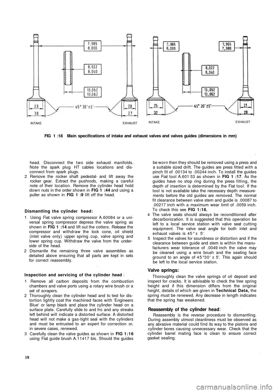
FIG 1 :18 Main specifications of intake and exhaust valves and valves guides (dimensions in mm)
head. Disconnect the t w o side exhaust manifolds.
Note the spark plug HT cables locations and dis-
connect from spark plugs.
2 Remove the rocker shaft pedestal- and lift away the
rocker gear. Extract the pushrods, making a careful
note of their location. Remove the cylinder head hold
down nuts in the order shown in FIG 1 :44 and using a
puller as shown in FIG 1 :9 lift off the head.
Dismantling the cylinder head:
1 Using Fiat valve spring compressor A.60084 or a uni-
versal spring compressor depress the valve spring as
shown in FIG 1 :14 and lift out the cotters. Release t h e
compressor and withdraw the lock cone, oil shield
(inlet valve only) upper spring cup, valve spring and
lower spring cup. Withdraw the valve from the under-
side of the head.
2 Dismantle the remaining three valve assemblies as
detailed above ensuring that all parts are kept in sets
for correct reassembly.
Inspection and servicing of the cylinder head :
1 Remove all carbon deposits from the combustion
chambers and valve ports using a rotary wire brush or a
set of scrapers.
2 Thoroughly clean the cylinder head and to test for dis-
tortion lightly coat the machined faces with 'Engineers
Blue' or lamp
black and place the cylinder head on a
surface plate. Carefully slide to and fro and any streaks
left behind will indicate a distorted surface. A distorted
head will not make a gas-tight seal with the cylinders
and must be entrusted to an expert for correction or,
in severe cases, renewed.
3 Carefully clean the valve guides as shown in FIG 1:16
using Fiat guide brush A.11417 bis. Should the guides
18Reassembly is the reverse procedure to dismantling.
During assembly utmost cleanliness must be observed as
any abrasive material could find its way to the pistons and
cylinder bores causing unnecessary wear. Check that the
cylinder barrel mating face is clean to ensure correct
gasket sealing.Reassembly of t h e cylinder head:
be worn then they should be removed using a press and
a suitable sized drift. The guides are press fitted with a
pinch fit of .00134 to .00244 inch. To install the guides
use Fiat tool A.601 53 as shown in FIG 1 :17. As the
guides have no stop ring during the press fitting, the
depth of insertion is determined by the Fiat tool. If the
tool is not available take the necessary depth measure-
ments before the old guides are removed. The normal
fit clearance between valve stem and guide is .00087 to
.00217 inch with a maximum wear limit of .0059 inch.
To check this see FIG 1:18.
4 The valve seats should always be reconditioned after
decarbonization. It is suggested that this operation be
left to a local service station with valve seat cutting
equipment. The valve seat angle for both inlet and
exhaust valves is 4 5 ° ± 5'.
5 Inspect the valves for soundness or distortion and if the
clearance between guide and stem is within the manu-
facturers wear tolerance of .0049 inch the valve may
be cleaned using a wire brush and the seating face
ground to an angle of 45°30' ± 5'. This again should
be left to the local service station.
Valve springs:
Thoroughly clean the valve springs of oil deposit and
inspect for cracks. It is advisable to check the free spring
height and if this dimension differs from the original
height, details of which are given in Technical Data, the
spring must be renewed. Any decrease in length indicates
that the spring has weakened.
Page 13 of 128
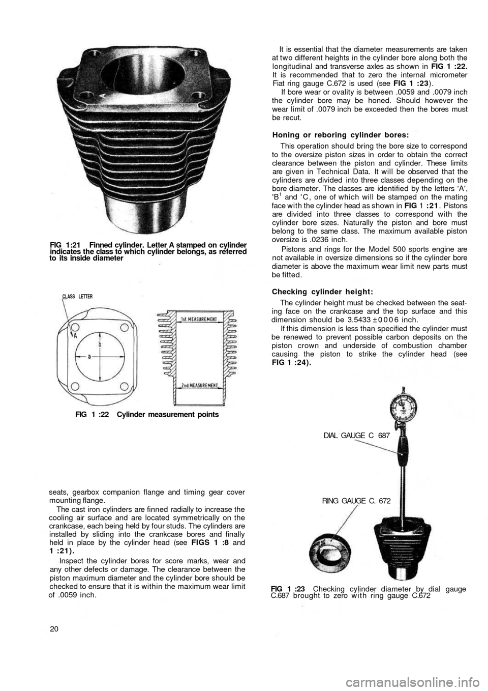
FIG 1:21 Finned cylinder. Letter A stamped on cylinder
indicates the class to which cylinder belongs, as referred
to its inside diameter
CLASS LETTER
FIG 1 :22 Cylinder measurement points
seats, gearbox companion flange and timing gear cover
mounting flange.
The cast iron cylinders are finned radially to increase the
cooling air surface and are located symmetrically on the
crankcase, each being held by four studs. The cylinders are
installed by sliding into the crankcase bores and finally
held in place by the cylinder head (see FIGS 1 :8 and
1 :21).
Inspect the cylinder bores for score marks, wear and
any other defects or damage. The clearance between the
piston maximum diameter and the cylinder bore should be
checked to ensure that it is within the maximum wear limit
of .0059 inch.
20FIG 1 :23 Checking cylinder diameter by dial gauge
C.687 brought to zero w i t h ring gauge C.672 DIAL GAUGE C 687
RING GAUGE C. 672 The cylinder height must be checked between the seat-
ing face on the crankcase and the top surface and this
dimension should be 3.5433 ±0006 inch.
If this dimension is less than specified the cylinder must
be renewed to prevent possible carbon deposits on the
piston crown and underside of combustion chamber
causing the piston to strike the cylinder head (see
FIG 1 :24). Checking cylinder height: This operation should bring the bore size to correspond
to the oversize piston sizes in order to obtain the correct
clearance between the piston and cylinder. These
limits
are given in Technical Data. It will be observed that the
cylinders are divided into three classes depending on the
bore diameter. The classes are identified by the letters 'A',
'B
1 and ' C , one of which will be stamped on the mating
face with the cylinder head as shown in FIG 1 :21. Pistons
are divided into three classes to correspond with the
cylinder bore sizes. Naturally the piston and bore must
belong to the same class. The maximum available piston
oversize is .0236 inch.
Pistons and rings for the Model 500 sports engine are
not available in oversize dimensions so if the cylinder bore
diameter is above the maximum wear limit new parts must
be fitted.Honing or reboring cylinder bores: It is essential that the diameter measurements are taken
at t w o different heights in the cylinder bore along both the
longitudinal and transverse axles as shown in FIG 1 :22.
It is recommended that to zero the internal micrometer
Fiat ring gauge C.672 is used (see FIG 1 :23).
If bore wear or ovality is between .0059 and .0079 inch
the cylinder bore may be honed. Should however the
wear limit of .0079 inch be exceeded then the bores must
be recut.
Page 14 of 128
Insert a .0079 ± .00197 inch thick oil paper gasket
between the crankcase and cylinder bottom face and a
.0236 to .0275 inch thick graphitized asbestos gasket
between the cylinder and cylinder head. The compression
of the gaskets on assembly will eliminate any very small
differences between the t w o mating surfaces.
Inspection of tappet seats:
The tappet seats should be checked for scoring and
correct clearance which must not exceed .00315 inch.
Should the clearance be greater than the maximum
specified the seating may be reamed to oversize dimen-
sions as detailed in Technical Data. Tappets are avail-
able in .00197 and .00394 inch diameter oversize.
1 :9 Piston assembly
Inspection:
Before inspection the pistons must be thoroughly
cleaned and the ring grooves and piston head decarbo-
nized. Check for deep score marks and signs of distortion
or fracture especially around the skirt and piston pin areas.
Using a feeler gauge ensure that the piston clearances in
the bore do not exceed a maximum of .0059 inch for the
Model 500 engine and .0079 inch for the Model 500
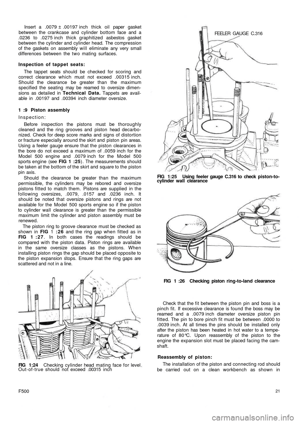
sports engine (see FIG 1 :25) . The measurements should
be taken at the bottom of the skirt and square to the piston
pin axis.
Should the clearance be greater than the maximum
permissible, the cylinders may be rebored and oversize
pistons fitted to m
atch them. Pistons are supplied in the
following oversizes, .0079, .0157 and .0236 inch. It
should be noted that oversize pistons and rings are not
available for the Model 500 sports engine so if the piston
to cylinder wall clearance is greater than the permissible
maximum limit the cylinder and piston assembly must be
renewed.
The piston ring to groove clearance must be checked as
shown in FIG 1 :26 and the ring gap when fitted as in
FIG 1 : 2 7. In both cases the readings should be
compared with the piston data. Piston rings are available
in the same oversize classes as the pistons. When
installing piston rings the gap should be placed opposite to
the piston expansion stops. Ensure that the ring gaps are
scattered and not in a line.
FIG 1:24 Checking cylinder head mating face f o r level
Out-of-true should not exceed .00315 i n c h
F50021
The installation of the piston and connecting rod should
be carried out on a clean workbench as shown in Reassembly of piston: Check that the f i t between the piston pin and boss is a
pinch fit. If excessive clearance is found the boss may be
reamed and a .0079 inch diameter oversize piston pin
fitted. The pin to bore pinch fit must be between .0000 to
.0039 inch. At all times the pins should be installed only
after the piston has been heated in hot water to a tempe-
rature of 80°C. Upon reassembly of the piston to the
engine the expansion slot must be placed facing the cam-
shaft.FIG 1 :26 Checking piston ring-to-land clearance FEELER GAUGE C.316
FIG 1:25 Using feeler gauge C.316 to check piston-to-
cylinder wall clearance
Page 22 of 128
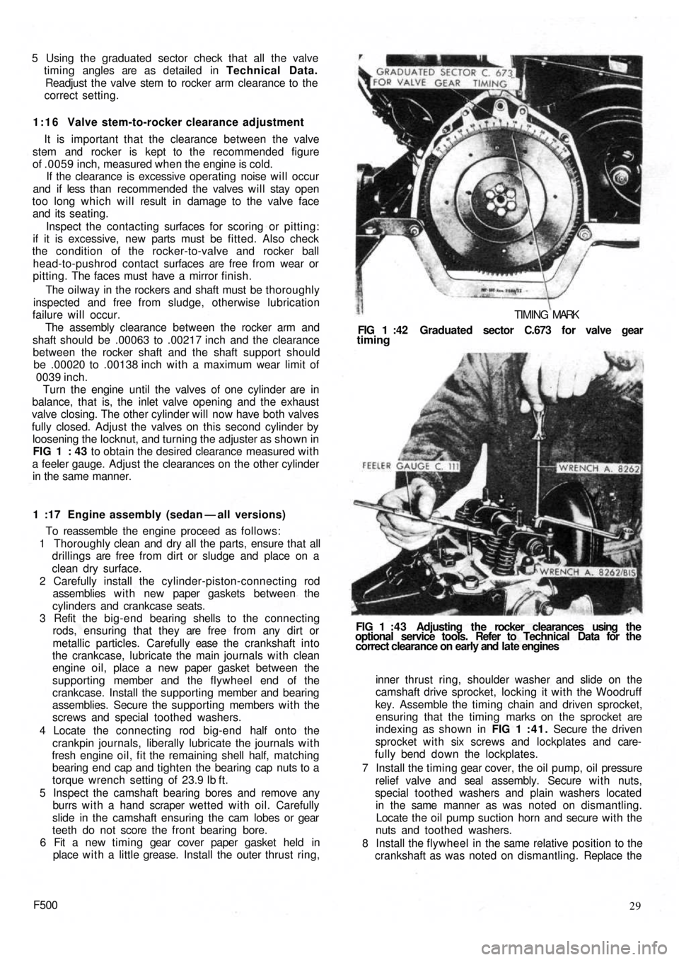
5 Using the graduated sector check that all the valve
timing angles are as detailed in Technical Data.
Readjust the valve stem to rocker arm clearance to the
correct setting.
1:16 Valve stem-to-rocker clearance adjustment
It is important that the clearance between the valve
stem and rocker is kept to the recommended figure
of .0059 inch, measured when the engine is cold.
If the clearance is excessive operating noise will occur
and if less than recommended the valves will stay open
too long which will result in damage to the valve face
and its seating.
Inspect the contacting surfaces for scoring or pitting:
if it is excessive, new parts must be fitted. Also check
the condition of the rocker-to-valve and rocker ball
head-to-pushrod contact surfaces are free from wear or
pitting. The faces must have a mirror finish.
The oilway in the rockers and shaft must be thoroughly
inspected and free from sludge, otherwise lubrication
failure will occur.
The assembly clearance between the rocker arm and
shaft should be .00063 to .00217 inch and the clearance
between the rocker shaft and the shaft support should
be .00020 to .00138 inch with a maximum wear limit of
0039 inch.
Turn the engine until the valves of one cylinder are in
balance, that is, the inlet valve opening and the exhaust
valve closing. The other cylinder will now have both valves
fully closed. Adjust the valves on this second cylinder by
loosening the locknut, and turning the
adjuster as shown in
FIG 1 : 43 to obtain the desired clearance measured with
a feeler gauge. Adjust the clearances on the other cylinder
in the same manner.
1 :17 Engine assembly (sedan — all versions)
To reassemble the engine proceed as follows:
1 Thoroughly clean and dry all the parts, ensure that all
drillings are free from dirt or sludge and place on a
clean dry surface.
2 Carefully install the cylinder-piston-connecting rod
assemblies w i t h new paper gaskets between the
cylinders and crankcase seats.
3 Refit the big-end bearing shells to the connecting
rods, ensuring that they are free from any dirt or
metallic particles. Carefully ease t h e crankshaft into
the crankcase, lubricate the main journals with clean
engine oil, place a new paper gasket between the
supporting member and the flywheel end of the
crankcase. Install the supporting member and bearing
assemblies. Secure the supporting members with the
screws and special toothed washers.
4 Locate the connecting rod big-end half onto the
crankpin journals, liberally lubricate the journals with
fresh engine oil, fit the remaining shell half, matching
bearing end cap and tighten the bearing cap nuts to a
torque wrench setting of 23.9 Ib ft.
5 Inspect the camshaft bearing bores and remove any
burrs w i t h a hand scraper wetted with oil. Carefully
slide in the camshaft ensuring the cam lobes or gear
teeth do not score the front bearing bore.
6 Fit a new timing gear cover paper gasket held in
place w i t h a little grease. Install the outer thrust ring,
F50029 inner thrust ring, shoulder washer and slide on the
camshaft drive sprocket, locking it with the Woodruff
key. Assemble the timing chain and driven sprocket,
ensuring that the timing marks on the sprocket are
indexing as shown in FIG 1 :41. Secure the driven
sprocket with six screws and lockplates and care-
fully bend down the lockplates.
7 Install the timing gear cover, the oil pump, oil pressure
relief valve and seal assembly. Secure w i t h nuts,
special toothed washers and plain washers located
in the same manner as was noted on dismantling.
Locate the oil pump suction horn and secure with the
nuts and toothed washers.
8 Install the flywheel in the same relative position to the
crankshaft as was noted on dismantling. Replace the FIG 1 : 4 3 Adjusting the rocker clearances using the
optional service tools. Refer to Technical Data for the
correct clearance on early and late engines FIG 1 :42 Graduated sector C.673 for valve gear
timing
TIMING MARK
Page 25 of 128
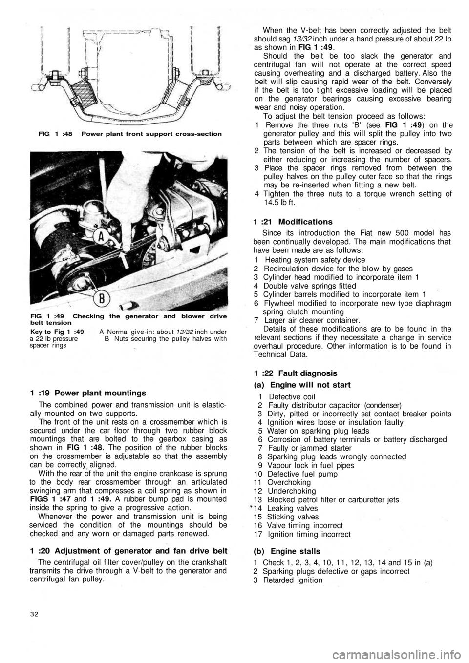
FIG 1 :48 Power plant front support cross-section
FIG 1 :49 Checking the generator and blower drive
belt tension
1 :19 Power plant mountings
The combined power and transmission unit is elastic-
ally mounted on two supports.
The front of the unit rests on a crossmember which is
secured under the car floor through two rubber block
mountings that are bolted to the gearbox casing as
shown in FIG 1 :48. The position of the rubber blocks
on the crossmember is adjustable so that the assembly
can be correctly aligned.
W i t h t h e rear of the unit the engine crankcase is sprung
to the b o d y rear crossmember through an articulated
swinging arm that compresses a coil spring as shown in
FIGS 1 :47 and 1 :49. A rubber bump pad is mounted
inside the spring to give a progressive action.
Whenever the power and transmission unit is being
serviced the condition of the mountings should be
checked and any worn or damaged parts renewed.
1 :20 Adjustment of generator and fan drive belt
The centrifugal oil filter cover/pulley on the crankshaft
transmits the drive through a V-belt to the generator and
centrifugal fan pulley.
32
(b) Engine stalls
1 Check 1, 2, 3, 4, 10, 1 1 , 12, 13, 14 and 15 in (a)
2 Sparking plugs defective or gaps incorrect
3 Retarded ignition 1 Defective coil
2 Faulty distributor capacitor (condenser)
3 Dirty, pitted or incorrectly set contact breaker points
4 Ignition wires loose or insulation faulty
5 Water on sparking plug leads
6 Corrosion of battery terminals or battery discharged
7 Faulty or jammed starter
8 Sparking plug leads wrongly connected
9 Vapour lock in fuel pipes
10 Defective fuel pump
11 Overchoking
12 Underchoking
13 Blocked petrol filter or carburetter jets
14 Leaking valves
15 Sticking valves
16 Valve timing incorrect
17 Ignition timing incorrect
(a) Engine will not start 1 :22 Fault diagnosis
Since its introduction the Fiat new 5 0 0 model has
been continually developed. The main modifications that
have been made are as follows:
1 Heating system safety device
2 Recirculation device for the blow-by gases
3 Cylinder head modified to incorporate item 1
4 Double valve springs fitted
5 Cylinder barrels modified to incorporate item 1
6 Flywheel modified to incorporate new type diaphragm
spring clutch mounting
7 Larger air cleaner container.
Details of these modifications are to be found in the
relevant sections if they necessitate a change in service
overhaul procedure. Other information is to be found in
Technical Data.
1 :21 Modifications
When the V-belt has been correctly adjusted the belt
should sag 13/32 inch under a hand pressure of about 22 lb
as shown in FIG 1 : 4 9.
Should the belt be too slack the generator and
centrifugal fan will not operate at the correct speed
causing overheating and a discharged battery. Also the
belt will slip causing rapid wear of the belt. Conversely
if the belt is too tight excessive loading will be placed
on the generator bearings causing excessive bearing
wear and noisy operation.
To adjust the belt tension proceed as follows:
1 Remove the three nuts ' B ' (see FIG 1 :49) on the
generator pulley and this will split the pulley into two
parts between which are spacer rings.
2 The tension of the belt is increased or decreased by
either reducing or increasing the number of spacers.
3 Place the spacer rings removed from between the
pulley halves on the pulley outer face so that the rings
may be re-inserted when fitting a new belt.
4 Tighten the three nuts to a torque wrench setting of
14.5
lb ft.
Key to Fig 1 :49 A Normal give-in: about 13/32 inch under
a 22 Ib pressure B Nuts securing the pulley halves with
spacer rings
Page 33 of 128
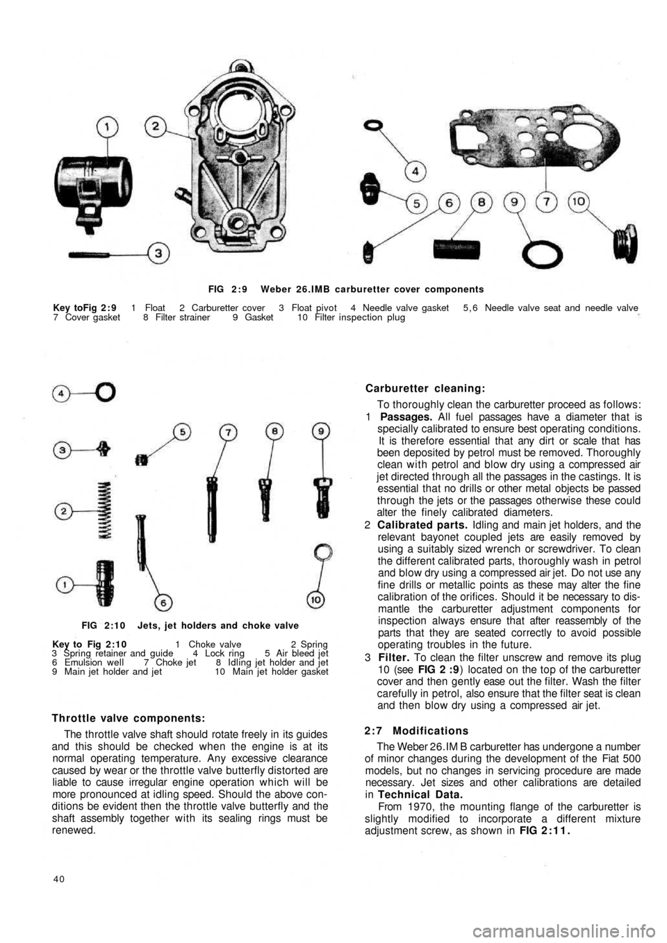
FIG 2 : 9 Weber 26.IMB carburetter cover components
Key toFig 2 : 9 1 Float 2 Carburetter cover 3 Float pivot 4 Needle valve gasket 5 , 6 Needle valve seat and needle valve
7 Cover gasket 8 Filter strainer 9 Gasket 10 Filter inspection plug
Carburetter cleaning:
To thoroughly clean the carburetter proceed as follows:
1 Passages. All fuel passages have a diameter that is
specially calibrated to ensure best operating conditions.
It is therefore essential that any dirt or scale that has
been deposited by petrol must be removed. Thoroughly
clean with petrol and blow dry using a compressed air
jet directed through all the passages in the castings. It is
essential that no drills or other metal objects be passed
through the jets or the passages otherwise these could
alter the finely calibrated diameters.
2 Calibrated parts. Idling and main jet holders, and the
relevant bayonet coupled jets are easily removed by
using a suitably sized wrench or screwdriver. To clean
the different calibrated parts, thoroughly wash in petrol
and blow dry using a compressed air jet. Do not use any
fine drills or metallic points as these may alter the fine
calibration of the orifices. Should it be necessary to dis-
mantle the carburetter adjustment components for
inspection always ensure that after reassembly of the
parts that they are seated correctly to avoid possible
operating troubles in the future.
3 Filter. To clean the filter unscrew and remove its plug
10 (see FIG 2 : 9) located on the top of the carburetter
cover and then gently ease o u t t h e filter. Wash the filter
carefully in petrol, also ensure that the filter seat is clean
and then blow dry using a compressed air jet.
2:7 Modifications
The Weber 26.IM B carburetter has undergone a number
of minor changes during the development of the Fiat 500
models, but no changes in servicing procedure are made
necessary. Jet sizes and other calibrations are detailed
in Technical Data.
From 1970, the mounting flange of the carburetter is
slightly modified to incorporate a different mixture
adjustment screw, as shown in FIG 2:11.
40
Throttle valve components:
The throttle valve shaft should rotate freely in its guides
and this should be checked when the engine is at its
normal operating temperature. Any excessive clearance
caused by wear or the throttle valve butterfly distorted are
liable to cause irregular engine operation which will be
more pronounced at idling speed. Should the above con-
ditions be evident then the throttle valve butterfly and the
shaft assembly together with its sealing rings must be
renewed.
FIG 2:10 Jets, jet holders and choke valve
Key to Fig 2:10 1 Choke valve 2 Spring
3 Spring retainer and guide 4 Lock ring 5 Air bleed jet
6 Emulsion well 7 Choke jet 8 Idling jet holder and jet
9 Main jet holder and jet 10 Main jet holder gasket
Page 41 of 128
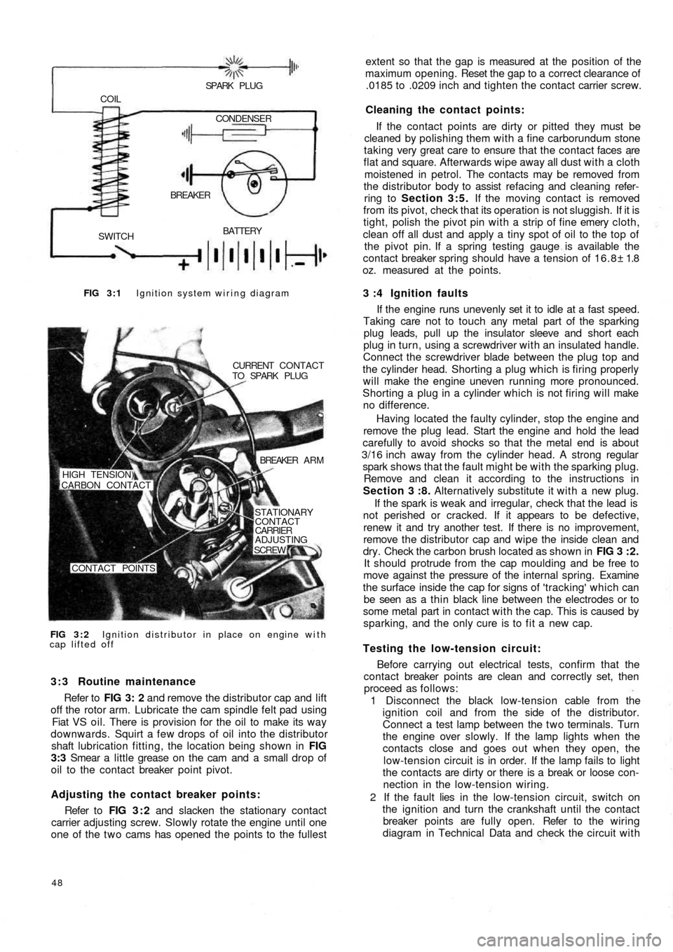
FIG 3 : 1 Ignition system wiring diagram
BATTERY
SWITCHBREAKER COIL
SPARK PLUG
CONDENSER
FIG 3 : 2 Ignition distributor in place on engine with
cap lifted offCURRENT CONTACT
TO SPARK PLUG
BREAKER A R M
STATIONARY
CONTACT
CARRIER
ADJUSTING
SCREW
CONTACT POINTS HIGH TENSION)
CARBON CONTACT
3 : 3 Routine maintenance
Refer to FIG 3: 2 and remove the distributor cap and lift
off the rotor arm. Lubricate the cam spindle felt pad using
Fiat VS oil. There is provision for the oil to make its way
downwards. Squirt a few drops of oil into the distributor
shaft lubrication fitting, the location being shown in FIG
3:3 Smear a little grease on the cam and a small drop of
oil to the contact breaker point pivot.
Adjusting the contact breaker points:
Refer to FIG 3 : 2 and slacken the stationary contact
carrier adjusting screw. Slowly rotate the engine until one
one of the t w o cams has opened the points to the fullest
48
extent so that the gap is measured at the position of the
maximum opening. Reset the gap to a correct clearance of
.0185 to .0209 inch and tighten the contact carrier screw.
Cleaning the contact points:
If the contact points are dirty or pitted they must be
cleaned by polishing them with a fine carborundum stone
taking very great care to ensure that the contact faces are
flat and square. Afterwards wipe away all dust with a cloth
moistened in petrol. The contacts may be removed from
the distributor body to assist refacing and cleaning refer-
ring to Section 3:5. If the moving contact is removed
from its pivot, check that its operation is not sluggish. If it is
tight, polish the pivot pin with a strip of fine emery cloth,
clean off all dust and apply a tiny spot of oil to the top of
the pivot pin. If a spring testing gauge is available the
contact breaker spring should have a tension of 16.8± 1.8
oz. measured at the points.
3 :4 Ignition faults
If the engine runs unevenly set it to idle at a fast speed.
Taking care not to touch any metal part of the sparking
plug leads, pull up the insulator sleeve and short each
plug in turn, using a screwdriver with an insulated handle.
Connect the screwdriver blade between the plug top and
the cylinder head. Shorting a plug which is firing properly
will make the engine uneven running more pronounced.
Shorting a plug in a cylinder which is not firing will make
no difference.
Having located the
faulty cylinder, stop the engine and
remove the plug lead. Start the engine and hold the lead
carefully to avoid shocks so that the metal end is about
3/16 inch away from the cylinder head. A strong regular
spark shows that the fault might be with the sparking plug.
Remove and clean it according to the instructions in
Section 3 :8. Alternatively substitute it with a new plug.
If the spark is weak and irregular, check that the lead is
not perished or cracked. If it appears to be defective,
renew it and try another test. If there is no improvement,
remove the distributor cap and wipe the inside clean and
dry. Check the carbon brush located as shown in FIG 3 : 2 .
It should protrude from the cap moulding and be free to
move against the pressure of the internal spring. Examine
the surface inside the cap for signs of 'tracking' which can
be seen as a thin black line between the electrodes or to
some metal part in contact with the cap. This is caused by
sparking, and the only cure is to fit a new cap.
Testing the low-tension circuit:
Before carrying out electrical tests, confirm that the
contact breaker points are clean and correctly set, then
proceed as follows:
1 Disconnect the black low-tension cable from the
ignition coil and from the side of the distributor.
Connect a test lamp between the t w o terminals. Turn
the engine over slowly. If the lamp lights when the
contacts close and goes out when they open, the
low-tension circuit is in order. If the lamp fails to light
the contacts are dirty or there is a break or loose con-
nection in the low-tension wiring.
2 If the fault lies in the
low-tension circuit, switch on
the ignition and turn the crankshaft until the contact
breaker points are fully open. Refer to the wiring
diagram in Technical Data and check the circuit with
Page 76 of 128
high bearing preload. To reset remove the wheel shaft
and fit a new resilient spacer. Repeat the rotation
torque test.
Swinging arm adjustment:
To adjust the swinging arm use Fiat fixture A.66064 as
shown in FIG 7 : 3 and proceed as follows:
1 At points A and B as indicated in FIG 7 : 4 between the
'estendblock' and the swinging arm to body front
mounting bracket fit three shims on each side. To
ensure that the shims are correctly centred use Fiat
alignment bar A.66057.
2 Whilst removing the alignment bar, carefully slip in the
mounting pin and screw on the nut. Once the rear
wheel geometry adjustment has been completed this
nut should be tightened to a torque wrench setting
of 43.4 to 50.6 Ib ft.
3 At points C and D (see FIG 7 : 4) , insert the number of
shims required to fill in the gap between the 'estend-
block' and the two fixture shoulders. Having deter-
mined the number of shims required both at locations
C and D, these must later be fitted between the
'estendblock' and the shoulders on the swinging arm
to body mounting bracket.
7 : 4 Coil springs
The coil springs should be thoroughly cleaned and all
traces of rust removed. Inspect the spring coils for hair
line cracks, which if evident, a new pair of springs must
be fitted to ensure correct vehicle height and stability.
Check the free
height and the height under loading of
the coil springs and these must correspond to the figures
quoted in Technical Data.
7:5 Installation of rear suspension assembly
To replace the rear suspension assembly proceed as
follows:
1 Insert the swinging arm inner end in the mounting
bracket which is welded onto the body floor. Place
between the 'estendblock' and bracket the number of
adjustment shims as previously determined using Fiat
fixture A.66064 as shown in FIG 7 : 4. Insert the Fiat
alignment bar A.66057 through 'estendblock' and
shims, aligning them with the holes in the mounting
bracket. Firmly hold the entire assembly using a garage
hydraulic jack if necessary, and carefully remove the
alignment bar and at the same time ease in t h e
mounting pin. Secure the nut which once the rear
wheels geometry has been checked must be tightened
to a torque wrench setting of 43.4 to 50.6 Ib/ft.
2 Screw in finger tight the three swinging arm external
bracket to body floor mounting screws together w i t h
the plain and spring washers. The screws will have to
be tightened to a torque wrench setting of 28.9 to
36.2 Ib/ft once the rear wheel geometry has been
adjusted.
3 Carefully insert the coil spring, lower insulator ring
onto the swinging arm, insert the spring on the shock
absorber which should be previously secured to the
arm and position the spring onto its seat on the arm.
Place the upper insulator ring onto the spring, raise the
suspension assembly using a garage hydraulic jack and
insert the spring onto its seating under the body floor.
F50083 4 Ensure that the shock absorber to floor rubber ring has
been correctly fitted and extend the shock absorber
until its upper mounting pin protrudes into the vehicle
through the hump in the floor panel. Secure the shock
absorber by its mounting nut and lockwasher having
first inserted the rubber ring and plain washer.
5 Refit the rear wheel housing in place, reconnect the
brake line to the connection on body floor and remove
the plug from the output hole in the brake fluid
reservoir. Bleed the hydraulic brake system as
described in Chapter 10.
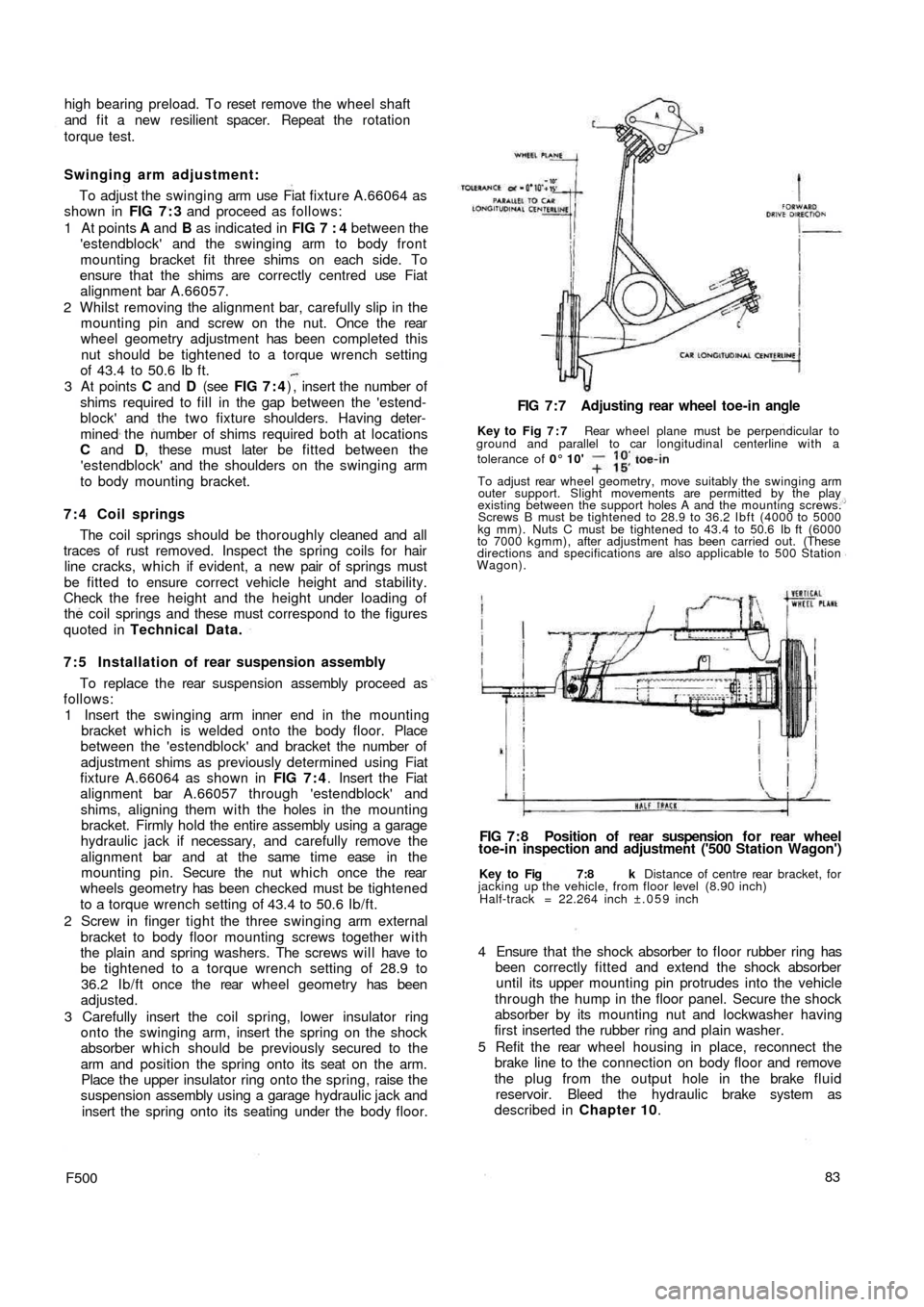
Key to Fig 7:8 k Distance of centre rear bracket, for
jacking up the vehicle, from floor level (8.90 inch)
Half-track = 22.264 inch ±.059 inch
FIG 7 : 8 Position of rear suspension f o r rear wheel
toe-in inspection and adjustment ('500 Station Wagon') FIG 7 : 7 Adjusting rear wheel toe-in angle
Key to Fig 7 : 7 Rear wheel plane must be perpendicular to
ground and parallel to car longitudinal centerline with a
tolerance of 0° 10'
To adjust rear wheel geometry, move suitably the swinging arm
outer support. Slight movements are permitted by the play
existing between the support holes A and the mounting screws.
Screws B must be tightened to 28.9 to 36.2 Ibft (4000 to 5000
kg mm). Nuts C must be tightened to 43.4 to 50.6 Ib ft (6000
to 7000 kgmm), after adjustment has been carried out. (These
directions and specifications are also applicable to 500 Station
Wagon).
Page 79 of 128
A tolerance of —10'.+ 15' is permitted providing
that the value is the same for both rear wheels. It is
important that both rear wheels are set to the same
angle otherwise uneven tyre wear and adverse handl-
ing conditions will result. When the wheel is parallel to
the centre line of the vehicle the pin of bracket
C.696/3 will be .216 inch apart from the pin of the
front suspension swinging arm.
7 Release the swinging arm outer support to body
mounting screws and position arm in such a way as to
obtain the condition as described in Number 6 above.
After the adjustment has been completed tighten
the outer support mounting screws to a torque wrench
setting of 28.9 to 36.2 Ib/ft. Also tighten the two
swinging arm pin nuts C (see FIG 7 : 7) to a torque
wrench setting of 43.4 to 50.6 Ib/ft. Take off the gauge
C.696 w i t h bracket and support C.696/3, and repeat
the check and adjustment operations on the other
wheel. Care must be taken to ensure that bracket
C.696/3 is reversed from the position previously used.
New 500 type 500D, 110F and 110L sedan and
station wagon:
After the rear suspension has been replaced, check
and, if necessary adjust the rear wheel geometry.
1 Inflate the tyres to the normal operating pressures.
2 Lower the car body so that the rear wheels are set at
90 deg. to the floor. This condition is obtained when
the lowermost portion of the sump is 6.61 inches from
the floor level for the new 500D model or the centre
rear bracket for jacking up the rear of t h e vehicle
8.9 inches from the floor level for the 500 Station
Wagon.
3 With the vehicle set to the above conditions check the
wheel geometry. The wheel plane must converge w i t h
the centre line of the vehicle by an angle of 0 deg. 10'
(—10', +15') toeing in at the front.
4 The wheel plane must be 22.343 ± .059 inches from
the centre line of the vehicle for the 500D model.
Whereas for the 500 Station Wagon the distance must
be 22.264 ± .059 inches.
5 To adjust the rear wheel toe-in adjust the positions of
the mounting screws A and B as shown in FIG 7:7.
86
7:7 Modifications
The new 500 Sedan (110F) and late 500 Station
Wagon are fitted with modified wheels side flexible
joints and rear control arm as shown in FIG 7:13.
Together w i t h these modifications a new design rear
coil spring has been fitted details of which are given in
Technical Data.
7 : 8 Fault diagnosis
(a) Irregular or abnormal tyre wear
1 Incorrect tyre pressure
2 Wheels out of balance
3 Wheels off centre
4 Misadjusted brakes
5 Weak or broken coil springs
6 Excessive load
7 Incorrect wheel alignment
(b) Sag on one wheel
1 Incorrect tyre pressure
2 Weak or broken coil spring
3 Wear of shock absorber causing poor dampening
action
(c) Squeaks, thumps or rattles
1 Wheels out of balance
2 Wheels off centre
3 Misadjusted brakes
4 Weak or broken coil springs or spring seats dislodged
5 Wear of shock absorbers causing poor dampening
action
6 Worn rubber bushings in control arms
7 Poor lubrication of wheel bearings
(d) Pull to one side
1 Incorrect tyre pressure
2 Misadjusted brakes
3 Distorted suspension arm
Page 104 of 128
CHAPTER 11
THE ELECTRICAL EQUIPMENT
11:1 Description
11:2 Battery
11:3 The generator
11:4 The starter
11:5 The control box
1 1 : 6 Fuses
1 1 : 7 Flasher unit
11:1 Description
All models covered by this manual have 12 volts
electrical systems in which the negative battery terminal
is earthed. There are three units in the regulator box to
control the charging circuit; a cut-out, a current regulator
and a voltage regulator. These are adjustable but it must
be stressed that accurate moving coil meters are required
when checking or altering the settings. Cheap and
unreliable instruments will make accurate adjustments
impossible.
There are wiring diagrams in Technical Data at the end
of this manual to enable those with electrical experience
to trace and correct wiring faults.
For t h e U.K. Market the headlamps are of the double
filament dipping renewable bulb type with adjustments
for individual beam settings.
The battery is located in the front compartment
forward of the petrol tank and the fuses to the rear o f the
petrol tank.
Detailed instructions for servicing the electrical equip-
ment will be found in this chapter, but it must be pointed
out that it is not sensible to try to repair that which is
seriously defective, electrically or mechanically. Such
equipment should be replaced by new units which can
be obtained on an exchange basis.
F500111
11 :8 Windscreen wipers
1 1 : 9 The lighting system
11:10 Panel and warning lights
11:11 The horn
11:12 Lighting and flasher switch
1 1 : 1 3 Fault diagnosis
11.2 The battery
This of the 12-volt lead/acid type and has to meet
heavy demands for current particularly in the winter. To
maintain the performance of the battery at its maximum
it is essential to carry out the following operations.
Keep the top of the battery and surrounding parts dry
and clean, as dampness can cause leakage between the
securing clamps and the battery terminals. Clean off any
corrosion from the metal parts of the battery mounting
with diluted ammonia and paint them with an anti-
sulphuric paint. If the terminal posts are corroded,
remove the cables and clean w i t h diluted ammonia.
Smear the posts w i t h petroleum jelly before remaking the
connections and fit the terminals securely. High electrical
resistance due to corrosion at the terminal posts is often
responsible for lack of sufficient current to operate the
starter motor.
Ensure t h a t the filler plugs are in good condition and
show no signs of cracks. This may cause leakage of
electrolyte and consequent corrosion. Test the condition
of the cells after topping-up the electrolyte level with
distilled water to just above the tops of the separators as
shown in FIG 11 :2 . Never add neat acid. If it is
necessary to make a new electrolyte due to loss by
spillage add sulphuric acid to the
distilled water.
It is highly dangerous to add water to acid.