fluid FIAT 500 1971 1.G Workshop Manual
[x] Cancel search | Manufacturer: FIAT, Model Year: 1971, Model line: 500, Model: FIAT 500 1971 1.GPages: 128, PDF Size: 9.01 MB
Page 72 of 128
CHAPTER 7
REAR SUSPENSION AND WHEELS
7:1
7:2
7:3
7:4Description
Removal of rear suspension assembly
Servicing swinging arms
Coil springs
7:1 Description
The rear wheels are independently sprung by means of
coil springs and V-shaped swinging arms acting on coil
springs and telescopic double acting hydraulic shock
absorbers. The swinging arms are m o u n t e d at their inner
ends on 'estendblocks', the coil spring is fitted at the outer
end of the swinging arm. At the wheel end of the suspen-
sion arm is attached a steel pressing to which the brake
backplate and wheel bearing housing are bolted so
forming a swinging unit to which is attached the road
wheel.
The inner pivots are so located vertical wheel move-
ments do not influence the drive shaft length which
means that there is no need to fit a splined joint at the
wheel end. Two taper roller bearings which are separated
by a specially designed collapsible spacer are located in
the rear wheel bearing housing and this carries the axle
shaft. The outer end of the axle shaft is flanged and it
is to this flange that the brake drum is bolted. The splined
inner end carries a rubber cushioned coupling to which
the drive shaft flange is attached.
7 : 2 Removal of rear suspension assembly
1 Jack-up the vehicle and place on firmly based stands.
Remove the road wheel on the side from which the
suspension unit is to be removed.
F50079 7:5
7:6
7:7
7:8Installation of rear suspension assembly
Checking and adjusting rear wheel toe-in
Modifications
Fault diagnosis
2 Using a garage hydraulic jack support the swinging
arm to facilitate the removal of the upper shock
absorber mounting nut which is located inside the
vehicle on the floor. To gain access to the nut remove
the rear wheel housing linings.
3 Unhook the parking brake shoe control lever return
spring.
4 Remove the three screws securing the drive shaft
flange to the flexible coupling. Pull back the sleeve and
remove the inner spring.
5 Remove the brake fluid reservoir cap, remove the filter
and plug the delivery hole in the brake f l u i d reservoir
and disconnect the flexible brake pipe from the
bracket on the body floor.
6 Disconnect the parking brake control tie rod by first
removing the cotter pin and removing the cable eye
from the pin on the shoe control lever. Release the
cable adjustment nuts and free the cable from the
fairlead on the swinging arm.
7 Using the hydraulic jack carefully lower the swinging
arm, fully retract the shock absorber by pushing in the
outer cylinder and carefully pull out the coil spring
together with its mounting rubber rings.
8 Remove the self-locking nut securing the swinging
arm to the internal support welded on the floor.
Extract the mounting pin and note the number and
arrangement of shims between the bushings and the
bracket. This will facilitate reassembly.
Page 76 of 128
high bearing preload. To reset remove the wheel shaft
and fit a new resilient spacer. Repeat the rotation
torque test.
Swinging arm adjustment:
To adjust the swinging arm use Fiat fixture A.66064 as
shown in FIG 7 : 3 and proceed as follows:
1 At points A and B as indicated in FIG 7 : 4 between the
'estendblock' and the swinging arm to body front
mounting bracket fit three shims on each side. To
ensure that the shims are correctly centred use Fiat
alignment bar A.66057.
2 Whilst removing the alignment bar, carefully slip in the
mounting pin and screw on the nut. Once the rear
wheel geometry adjustment has been completed this
nut should be tightened to a torque wrench setting
of 43.4 to 50.6 Ib ft.
3 At points C and D (see FIG 7 : 4) , insert the number of
shims required to fill in the gap between the 'estend-
block' and the two fixture shoulders. Having deter-
mined the number of shims required both at locations
C and D, these must later be fitted between the
'estendblock' and the shoulders on the swinging arm
to body mounting bracket.
7 : 4 Coil springs
The coil springs should be thoroughly cleaned and all
traces of rust removed. Inspect the spring coils for hair
line cracks, which if evident, a new pair of springs must
be fitted to ensure correct vehicle height and stability.
Check the free
height and the height under loading of
the coil springs and these must correspond to the figures
quoted in Technical Data.
7:5 Installation of rear suspension assembly
To replace the rear suspension assembly proceed as
follows:
1 Insert the swinging arm inner end in the mounting
bracket which is welded onto the body floor. Place
between the 'estendblock' and bracket the number of
adjustment shims as previously determined using Fiat
fixture A.66064 as shown in FIG 7 : 4. Insert the Fiat
alignment bar A.66057 through 'estendblock' and
shims, aligning them with the holes in the mounting
bracket. Firmly hold the entire assembly using a garage
hydraulic jack if necessary, and carefully remove the
alignment bar and at the same time ease in t h e
mounting pin. Secure the nut which once the rear
wheels geometry has been checked must be tightened
to a torque wrench setting of 43.4 to 50.6 Ib/ft.
2 Screw in finger tight the three swinging arm external
bracket to body floor mounting screws together w i t h
the plain and spring washers. The screws will have to
be tightened to a torque wrench setting of 28.9 to
36.2 Ib/ft once the rear wheel geometry has been
adjusted.
3 Carefully insert the coil spring, lower insulator ring
onto the swinging arm, insert the spring on the shock
absorber which should be previously secured to the
arm and position the spring onto its seat on the arm.
Place the upper insulator ring onto the spring, raise the
suspension assembly using a garage hydraulic jack and
insert the spring onto its seating under the body floor.
F50083 4 Ensure that the shock absorber to floor rubber ring has
been correctly fitted and extend the shock absorber
until its upper mounting pin protrudes into the vehicle
through the hump in the floor panel. Secure the shock
absorber by its mounting nut and lockwasher having
first inserted the rubber ring and plain washer.
5 Refit the rear wheel housing in place, reconnect the
brake line to the connection on body floor and remove
the plug from the output hole in the brake fluid
reservoir. Bleed the hydraulic brake system as
described in Chapter 10.
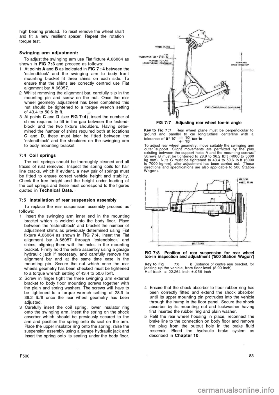
Key to Fig 7:8 k Distance of centre rear bracket, for
jacking up the vehicle, from floor level (8.90 inch)
Half-track = 22.264 inch ±.059 inch
FIG 7 : 8 Position of rear suspension f o r rear wheel
toe-in inspection and adjustment ('500 Station Wagon') FIG 7 : 7 Adjusting rear wheel toe-in angle
Key to Fig 7 : 7 Rear wheel plane must be perpendicular to
ground and parallel to car longitudinal centerline with a
tolerance of 0° 10'
To adjust rear wheel geometry, move suitably the swinging arm
outer support. Slight movements are permitted by the play
existing between the support holes A and the mounting screws.
Screws B must be tightened to 28.9 to 36.2 Ibft (4000 to 5000
kg mm). Nuts C must be tightened to 43.4 to 50.6 Ib ft (6000
to 7000 kgmm), after adjustment has been carried out. (These
directions and specifications are also applicable to 500 Station
Wagon).
Page 80 of 128
CHAPTER 8
FRONT SUSPENSION AND HUBS
8:1
8:2
8:3
8:4
8:5
8:6Description
Front suspension removal and dismantling
Leaf spring
Swinging arms
Kingpin housing
Steering knuckle and wheel hub
8:1 Description
The independent front suspension assembly fitted to
the 'new 500' range comprises a transverse leaf spring
which is anchored to the body through two rubber
mountings and kingpins through 'estendblocks' as
shown in FIG 8:1. The leaf spring also acts as an anti-
roll bar which gives normal spring reaction even when the
front road wheels encounter a rough road surface.
Special polyethylene insulating strips are fitted
between the five springs leaves which are all clamped
together by t w o rubber cushioned clamps.
Upper movement of the kingpins in the swinging arm
is obtained by 'estendblocks'. The half arms are anchored
to the body as shown in FIG 8 : 3 and pivot on their pins
through rubber bushes. Double acting hydraulic shock
absorbers are fitted to the kingpin housings at the lower
end and anchored at the top to the vehicle body. Two
rubber buffers are secured to brackets mounted onto the
body to limit the spring oscillations. The spring centre
bolt is also fitted with a rubber pad.
8 : 2 Front suspension removal and
dismantling
To remove the front suspension assembly proceed as
follows:
F50087
1 Remove the hub caps and carefully slacken the road
wheel retaining bolts. Using a garage hydraulic jack
raise the front of the vehicle and place on firmly
based stands. Remove the road wheels.
2 Disconnect the steering linkages from the pitman arm,
the drag link and the steering knuckle arms.
3 Remove the shock absorber upper mounting nut from
the body, lift away the half rubber bush and push d o w n
the outer cylinder.
4 Blank off the brake fluid reservoir outlet by inserting
a suitable wooden peg through the reservoir filler
opening and disconnect the brake hydraulic lines at
the wheel cylinders.
5 Fit Fiat crossbeam Arr.2072 under the leaf spring
and support this, using a garage hydraulic jack.
6 Remove the self-locking nut securing the leaf spring
to the kingpin housing and ease o u t the spring
mounting bolt taking care not to damage the thread.
Also remove the nuts securing the swinging arm pin
to studs on the body and remove the swinging arm
assembly. Carefully lift out the adjusting shims and
spacers from the studs making a careful note of the
number of the shims and their locations.
7 Remove the nuts securing the leaf spring elastic
mounting to the body (see FIG 8 : 4) , and lower the 8:7
8:8
8:9
8:10
8:11Hydraulic damper
Front suspension assembly and
installation
Steering geometry
Modifications
Fault diagnosis
Page 85 of 128
1
2
6
3
8
11
13
17
19
22
25
27
29
31
33
36
35 323430 28
26
24232120 ,1816 15 14 12 10 .9 .15 4
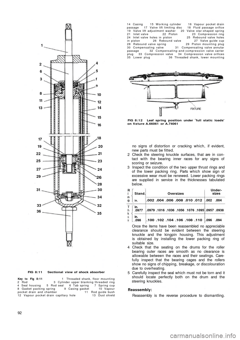
FIG 8:11 Sectional view of shock absorber
Key to Fig 8:11 1 Threaded shank, floor mounting
2 R o d 3 Cylinder upper blanking threaded ring
4 Seal housing 5 Rod seal 6 Tab spring 7 Spring cup
8 Gasket packing spring 9 Casing gasket 10 Vapour
pocket drain and chamber 11 Rod guide bush
12 Vapour pocket drain capillary hole 13 Dust shield
92
14 Casing 15 Working cylinder 16 Vapour pocket drain
passage 17 Valve lift limiting disc 18 Fluid passage orifice
19 Valve lift adjustment washer 20 Valve star-shaped spring
21 Inlet valve 22 Piston 23 Compression ring
24 Inlet valve holes in piston 25 Rebound valve holes
in piston 26 Rebound valve 27 Valve guide cup
28 Rebound valve spring 29 Piston mounting plug
30 Compensating valve 31 Compensating valve annular
passage 32 Compensating-and-compression valve carrier
plug 33 Compression valve 34 Compression valve orifices
35 Lower plug 36 Threaded shank, lower mounting
FIXTURE
FIG 8:12 Leaf spring position under full static loads'
on fixture A.66061 or A.74061
no signs of distortion or cracking which, if evident,
new parts must be fitted.
2 Check the steering knuckle surfaces, that are in con-
tact with the bearing inner races for any signs of
scoring or seizure.
3 Inspect the condition of the two upper thrust rings and
of the lower packing ring. Parts which show sign of
excessive wear must be renewed. Lower packing rings
are supplied in service in the thicknesses tabulated
below.
Once the items have been reassembled no appreciable
clearance should be evident between the steering
knuckle and the kingpin housing. This adjustment
is obtained by installing the lower packing ring of
suitable size.
4 Check that the seating on the drums for the roller
bearing outer races are smooth as no clearance is
allowable between the races and their seatings. Care-
fully inspect that the bearing cages and the rollers
show no signs of chipping, breakage, or discolouration
due to overheating.
5 Carefully inspect the seal which must not be torn and it
should locate perfectly both on the drum and the
steering knuckles.
Reassembly:
Reassembly is the reverse procedure to dismantling.
OversizesUnder-
sizes
.002 .004 .006 .008 .010 .012
.0979 .1016 .1036 .1056 .1076 .1095
.100 .102 .104 .106 .108 .110
.002 .004
.0957 .0938
.096 .094
Stand.
in.
in..0977
in..098
Page 86 of 128
8 : 7 Hydraulic damper:
Description:
The front and rear shock absorbers are of the telescopic
double acting type. Their dampening action takes place
directly on the suspension without the use of any
intermediate linkage. The shock absorber comprises a
cylindrical body formed by to coaxial tubes 14 and 15
(see FIG 8:11), the inner tube acting as the working
cylinder and the outer one as a casing. The fluid reservoir
being located between the two sections. A third outer
cylinder 13 shields the rod 2 from any road dirt.
On the top the cylinder body is enclosed by a bush 1 1 ,
oil seals 5 and 9 and a housing 4. The rod 2 slides through
the seals 5, the upper end is fixed into the vehicle body
floor and its lower end carries the piston 22 on which
rebound 26 and inlet valves 21 are arranged.
The bottom of the shock absorber is closed by a plug
35 with a threaded shank 36 for the shock absorber to be
mounted onto the suspension unit. The cylinder 15 and
carrier plug 32 is mounted with a compensation valve
30 and a compression valve 33. The piston is provided
with two rows of orifices. The internal row is blanked
underneath by the rebound valve which operates
downwards. The external row is blanked by the inlet
valve which opens upwards. Hydraulic shock absorbers
fitted since March 1959 are provided w i t h a vapour
pocket bleeder from the cylinder exterior. The bleeder
device comprises a capillary
hole 12 interconnecting the
inner cylinder 15 with the upper chamber 10 and also a
passage tube 16 from the upper chamber to the fluid
reservoir. Any vapour pockets in the pressure cylinder
are excluded past the capillary hole 12 into the chamber
10 from which they flow downwards during shock
absorber operation through the passage 16 in a light
fluid stream and up to the top of the reservoir with the
reservoir fluid.
Dismantling and inspection:
Normally during service if a shock absorber becomes
weak in operation then a new unit should be fitted.
Should however, it be necessary for the original unit to
be overhauled proceed as follows:
1 Thoroughly clean the outer casing in petrol and blow
dry using a compressed air jet.
2 Firmly clamp the lower shank of the shock absorber
in a vice and telescope upwards the outer casing and
using Fiat wrench A.56024 unscrew the upper
threaded ring 3 (see FIG 8:11).
3 Remove the shock absorber from the vice and carefully
remove the inner cylinder 15 using a screwdriver
inserted in the cylinder bottom chamfer and remove
the lower plug 32 which carries the compression and
compensation valves.
4 Push the rod i n t o the cylinder 15 and clamp the upper
shank in a vice. Unscrew the plug 29, and carefully
remove the piston 22 together with the inlet and
rebound valves. Withdraw the rod 2 from the cylinder
15 and remove the seal gasket, the housing, and
threaded ring. Thoroughly wash all parts in petrol and
carefully blow dry using a c
ompressed air jet. The
following parts should be inspected as follows.
Check that the inlet, rebound and compensation valve
discs are not deformed or show signs of cracking.
F50093 Inspect the surfaces of the piston, the seal ring and the
compression valve to ensure that they are smooth and
hydraulic fluid tight. Check that the rebound and
compression valve springs and upper seal gasket
springs are not broken or weak. Carefully inspect the
t w o seal gaskets for damage or wear and it is recom-
mended that they are renewed upon reassembly.
Check that the rod and the cylinders show no sign of
deformation and that the air pocket evacuating
passage is not blocked. Also check that the capillary
hole 12 is not blocked. Any parts which show signs
of wear or damage must be renewed.
Reassembly:
Reassembly of the shock absorber is the reverse
procedure to dismantling. Special care must be taken
when refilling the shock absorber w i t h Fiat SA1 oil
otherwise its operating characteristics will be altered.
The hydraulic fluid capacity for the front shock
absorbers is .112 imperial quarts.
The hydraulic capacity for the rear shock absorbers is
.088 imperial quarts. Only Fiat—SA1 oil must be
used.
To insert the components into the shock absorber
body proceed as follows:
1 Mount the piston on the rod, and insert the piston and
rod assembly into the cylinder 15 (see FIG 8:11).
2 Push the piston against the bush 11 and then very
carefully pour the correct amount of hydraulic fluid
up to about j inch from the edge.
3 Press f i t t h e plug 32 and pour the remaining fluid into
the casing 14.
4 Insert the cylinder 15 into the casing 14 and tighten
the upper threaded ring 3.
8 :8 Front suspension assembly and installation
1 Attach Fiat fixture A.66061 to the springs as shown
in FIG 8:12 and load it using the centre screw on the
fixture until the index 'Nuova 500' appears below
the crossbeam lower edge. It is in this position the
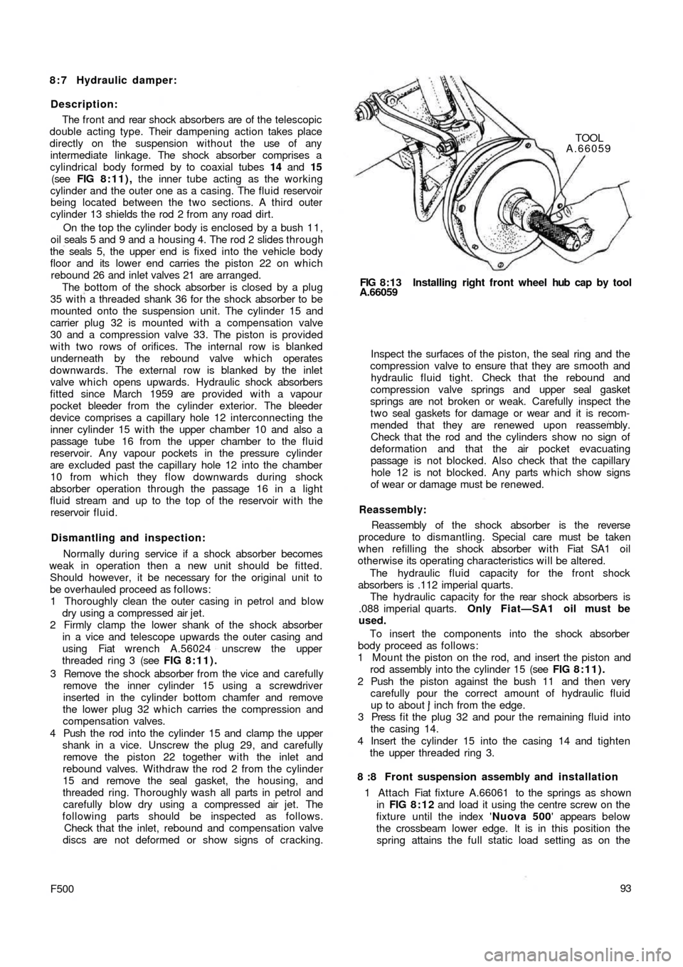
spring attains the full static load setting as on the FIG 8:13 Installing right front wheel hub cap by tool
A.66059TOOL
A.66059
Page 88 of 128
VERTICAL LINE DB
S
EB
OIL SUMPF
GF
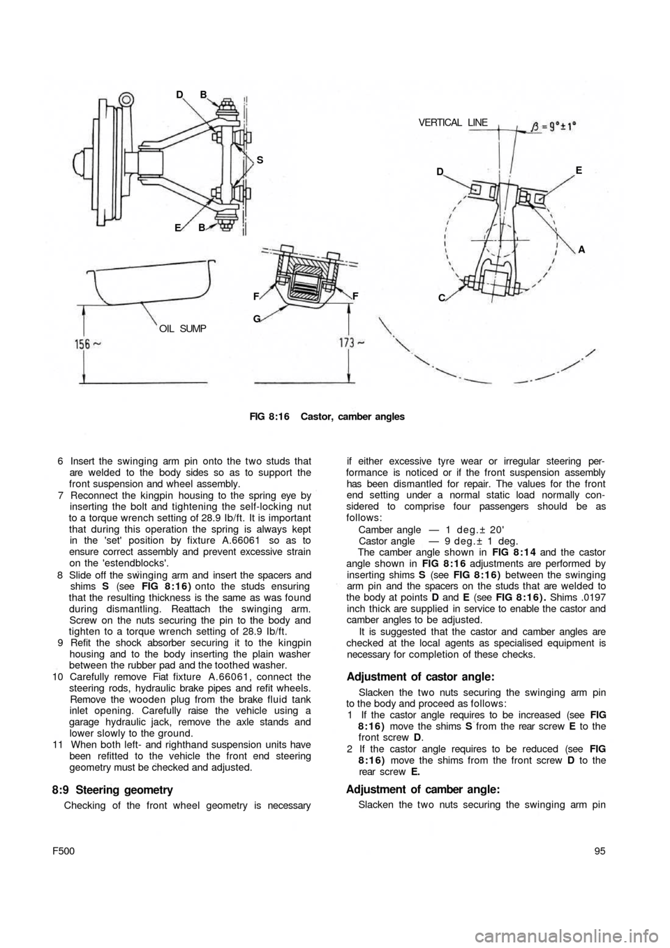
FIG 8:16 Castor, camber angles
6 Insert the swinging arm pin onto the two studs that
are welded to the body sides so as to support the
front suspension and wheel assembly.
7 Reconnect the kingpin housing to the spring eye by
inserting the bolt and tightening the self-locking nut
to a torque wrench setting of 28.9 Ib/ft. It is important
that during this operation the spring is always kept
in the 'set' position by fixture A.66061 so as to
ensure correct assembly and prevent excessive strain
on the 'estendblocks'.
8 Slide off the swinging arm and insert the spacers and
shims S (see FIG 8:16) onto the studs ensuring
that the resulting thickness is the same as was found
during dismantling. Reattach the swinging arm.
Screw on the nuts securing the pin to the body and
tighten to a torque wrench setting of 28.9 Ib/ft.
9 Refit the shock absorber securing it to the kingpin
housing and to the body inserting the plain washer
between the rubber pad and the toothed washer.
10 Carefully remove Fiat fixture A.66061, connect the
steering rods, hydraulic brake pipes and refit wheels.
Remove the wooden plug from the brake fluid tank
inlet opening. Carefully raise the vehicle using a
garage hydraulic jack, remove the axle stands and
lower slowly to the ground.
11 When both left- and righthand suspension units have
been refitted to the vehicle the front end steering
geometry must be checked and adjusted.
8:9 Steering geometry
Checking of the front wheel geometry is necessary
95
F500
if either excessive tyre wear or irregular steering per-
formance is noticed or if the front suspension assembly
has been dismantled for repair. The values for the front
end setting under a normal static load normally con-
sidered to comprise four passengers should be as
follows:
Camber angle — 1 d e g . ± 20'
Castor angle — 9 deg.± 1 deg.
The camber angle shown in FIG 8:14 and the castor
angle shown in FIG 8 : 1 6 adjustments are performed by
inserting shims S (see FIG 8 : 1 6 ) between the swinging
arm pin and the spacers on the studs that are welded to
the body at points D and E (see FIG 8:16). Shims .0197
inch thick are supplied in service to enable the castor and
camber angles to be adjusted.
It is suggested that the castor and camber angles are
checked at the local agents as specialised equipment is
necessary for completion of these checks.
Adjustment of castor angle:
Slacken the t w o nuts securing the swinging arm pin
to the body and proceed as follows:
1 If the castor angle requires to be increased (see FIG
8:16) move the shims S from the rear screw E to the
front screw D.
2 If the castor angle requires to be reduced (see FIG
8:16) move the shims from the front screw D to the
rear screw E.
Adjustment of camber angle:
Slacken the t w o nuts securing the swinging arm pin DE
A
C
Page 96 of 128
CHAPTER 10
THE BRAKING SYSTEM
10:1 Description
10:2 Maintenance
10:3 Front brakes
10:4 Rear brakes
10:5 Master cylinder
10:6 Wheel cylinder10:7 Self-adjusting device
10:8 Removing a flexible hose
10:9 Brake fluid reservoir
10:10 Bleeding the system
10:11 Hand parking brake
10:12 Fault diagnosis
10:1 Description
All four drum brake units are hydraulically operated by
the brake pedal and the handbrake lever operates the rear
brakes only through a mechanical linkage which normally
requires no separate adjustment (see FIG 10:1).
The brake units are of the internal expanding type with
one leading and one trailing shoe to each brake. A double
ended wheel cylinder expands both shoes into contact
with the drum under hydraulic pressure from the master
cylinder. When the brake pedal pressure is released the
shoes are retracted by means of springs.
The brake pedal is directly coupled to the hydraulic
master cylinder where pressure on the fluid is generated.
This is transmitted to the brakes by a system of metal and
flexible pipes.
The braking units fitted to the new 500 Sedan models
are equipped with a specially designed brake shoe
clearance self-adjustment device which eliminates the
need for manual adjustment of the brake shoe to drum
clearance as is normal practice w i t h a conventional
braking system. Every time the brake pedal is depressed
the self-adjustment device automatically takes up the
excess clearance which may have developed between
the lining and the drum due to normal service wear.
The brake units fitted to the 500 Station wagon model
have a normal brake adjuster which should be used when
F500103 the brake pedal travel becomes excessive. The adjuster
is shown in FIG 10:3.
On later models a dual circuit system is used. It is
described in Section 10:12
10:2 Maintenance
Brake adjustment {Station Wagon)
Jack each wheel in turn after first chocking the remain-
ing three wheels and releasing the handbrake. Depress
the brake pedal so as to force the brake shoes against the
drum and keeping the shoes in this position turn the
adjuster nuts until they contact the shoes and then back
the nuts 20 deg. This will correctly set the shoe to drum
clearance which should be checked for binding by
releasing the brake pedal and ensuring that the road wheel
revolves freely. The operation should then be repeated
on the other wheels. This adjustment will automatically
set the handbrake.
Preventative maintenance:
1 Thoroughly inspect the metal hydraulic fluid lines for
rusting, cracking or flattening and that they are
located away from any sharp edges which could cause
a failure.
Page 97 of 128
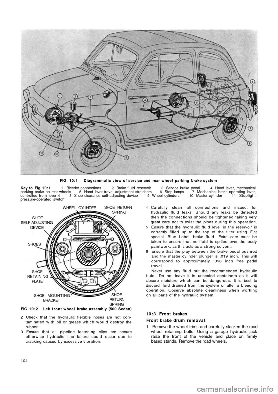
FIG 10:1 Diagrammatic view of service and rear wheel parking brake system
Key to Fig 10:1 1 Bleeder connections 2 Brake fluid reservoir 3 Service brake pedal 4 Hand lever, mechanical
parking brake on rear wheels 5 Hand lever travel adjustment stretchers 6 Stop lamps 7 Mechanical brake operating lever,
controlled from lever 4 8 Shoe clearance self-adjusting device 9 Wheel cylinders 10 Master cylinder 11 Stoplight
pressure-operated switch
FIG 10:2 Left front wheel brake assembly (500 Sedan)
SHOE
RETURN
SPRINGSHOE MOUNTING
BRACKET SHOE
RETAINING
PLATE SHOES
DEVICESHOE
SELF-ADJUSTING
WHEEL CYLINDERSHOE RETURNSPRING
2 Check that the hydraulic flexible hoses are not con-
taminated with oil or grease which would destroy the
rubber.
3 Ensure that all pipeline fastening clips are secure
otherwise hydraulic line failure could occur due to
cracking caused by excessive vibration.
104
4 Carefully clean all connections and inspect for
hydraulic fluid leaks. Should any leaks be detected
then the connections should be tightened taking very
great care not to twist the pipes during this operation.
5 Ensure that the hydraulic fluid level in the reservoir is
correctly filled up to the top of the filter using Fiat
special 'Blue Label' brake fluid. Extra care must be
taken to ensure that no fluid is spilled over the body
paintwork, as this acts as a strong solvent.
6 Ensure that the play between the brake pedal pushrod
and the master cylinder plunger is .019 inch. This will
correspond to approximately .098 inch free pedal
travel.
Never use any fluid but the recommended hydraulic
fluid. Do not leave it in unsealed containers as it will
absorb moisture which can be dangerous. It is best to
discard fluid drained from the system or after a bleeding
operation. Observe absolute cleanliness when working
on all parts of the hydraulic system.
10:3 Front brakes
Front brake drum removal:
1 Remove the wheel trims and carefully slacken the road
wheel retaining bolts. Using a garage hydraulic jack
raise the front of the vehicle and place on firmly
based stands. Remove the road wheels.
Page 99 of 128
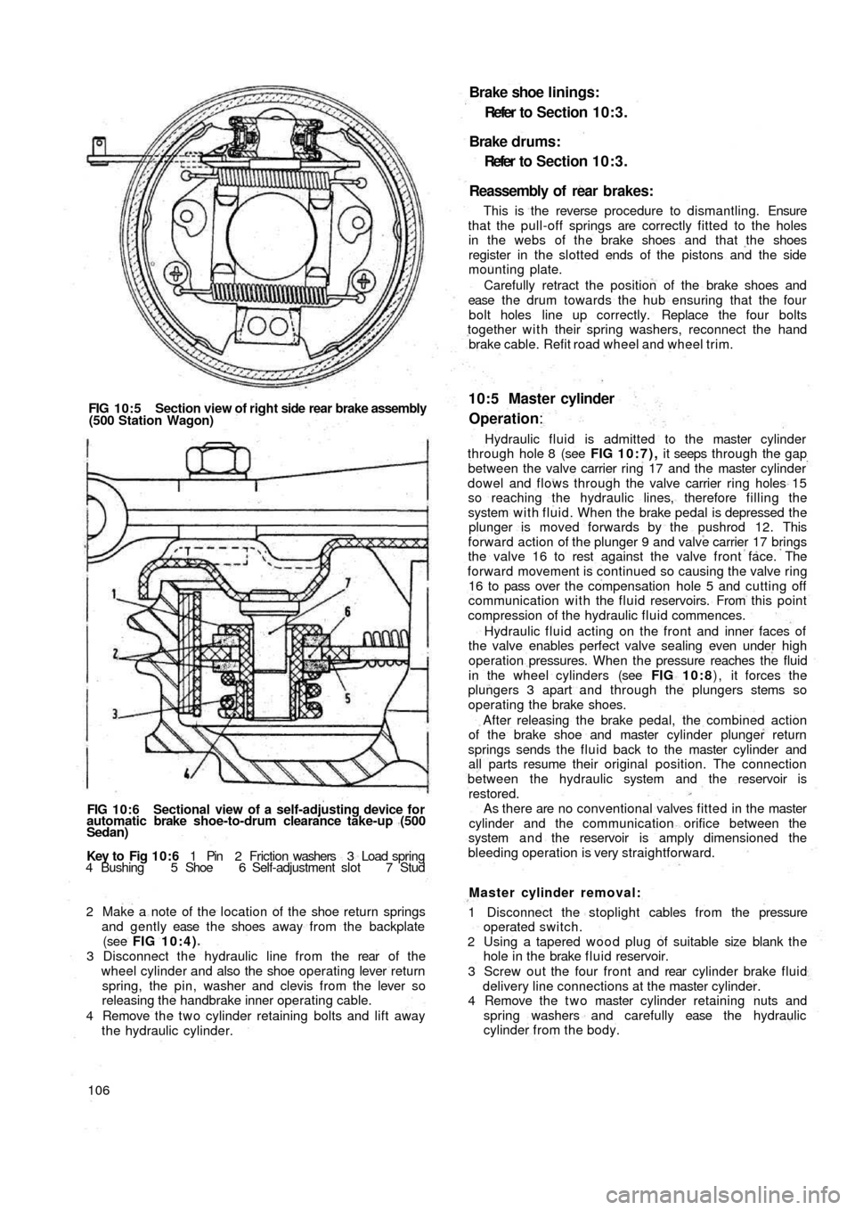
FIG 10:5 Section view of right side rear brake assembly
(500 Station Wagon)
FIG 10:6 Sectional view of a self-adjusting device for
automatic brake shoe-to-drum clearance take-up (500
Sedan)
Key to Fig 1 0 : 6 1 Pin 2 Friction washers 3 Load spring
4 Bushing 5 Shoe 6 Self-adjustment slot 7 Stud
2 Make a note of the location of the shoe return springs
and gently ease t h e shoes away from the backplate
(see FIG 10:4)
3 Disconnect the hydraulic line from the rear of t h e
wheel cylinder and also the shoe operating lever return
spring, the pin, washer and clevis from the lever so
releasing the handbrake inner operating cable.
4 Remove the t w o cylinder retaining bolts and lift away
the hydraulic cylinder.
106
Brake shoe linings:
Refer t o Section 10:3.
Brake drums:
Refer to Section 10:3.
Reassembly of rear brakes:
This is the reverse procedure to dismantling. Ensure
that the pull-off springs are correctly fitted to the holes
in the webs of the brake shoes and that the shoes
register in the slotted ends of the pistons and the side
mounting plate.
Carefully retract the position of the brake shoes and
ease t h e d r u m towards the hub ensuring that the four
bolt holes line up correctly. Replace the four bolts
together with their spring washers, reconnect the hand
brake cable. Refit road wheel and wheel trim.
10:5 Master cylinder
Operation:
Hydraulic fluid is admitted to the master cylinder
through hole 8 (see FIG 10:7), it seeps through the gap
between the valve carrier ring 17 and the master cylinder
dowel and flows through the valve carrier ring holes 15
so reaching the hydraulic lines, therefore filling the
system w i t h fluid. When the brake pedal is depressed the
plunger is moved forwards by the pushrod 12. This
forward action of the plunger 9 and valve carrier 17 brings
the valve 16 to rest against the valve front face. The
forward movement is continued so causing the valve ring
16 to pass over the compensation hole 5 and cutting off
communication with the fluid reservoirs. From this point
compression of the hydraulic fluid commences.
Hydraulic fluid acting on the front and inner faces of
the valve enables perfect valve sealing even under high
operation pressures. When the pressure reaches the fluid
in the wheel cylinders (see FIG 10:8) , it forces the
plungers 3 apart and through the plungers stems so
operating the brake shoes.
After releasing the brake pedal, the combined action
of the brake shoe and master cylinder plunger return
springs sends the fluid back to the master cylinder and
all parts resume their original position. The connection
between the hydraulic
system and the reservoir is
restored.
As there are no conventional valves fitted in the master
cylinder and the communication orifice between the
system a n d the reservoir is amply dimensioned the
bleeding operation is very straightforward.
Master cylinder removal:
1 Disconnect the stoplight cables from the pressure
operated switch.
2 Using a tapered w o o d plug of suitable size blank t h e
hole in the brake f l u i d reservoir.
3 Screw out the four front and rear cylinder brake fluid
delivery line connections at the master cylinder.
4 Remove the t w o master cylinder retaining nuts and
spring washers and carefully ease the hydraulic
cylinder from the body.
Page 100 of 128
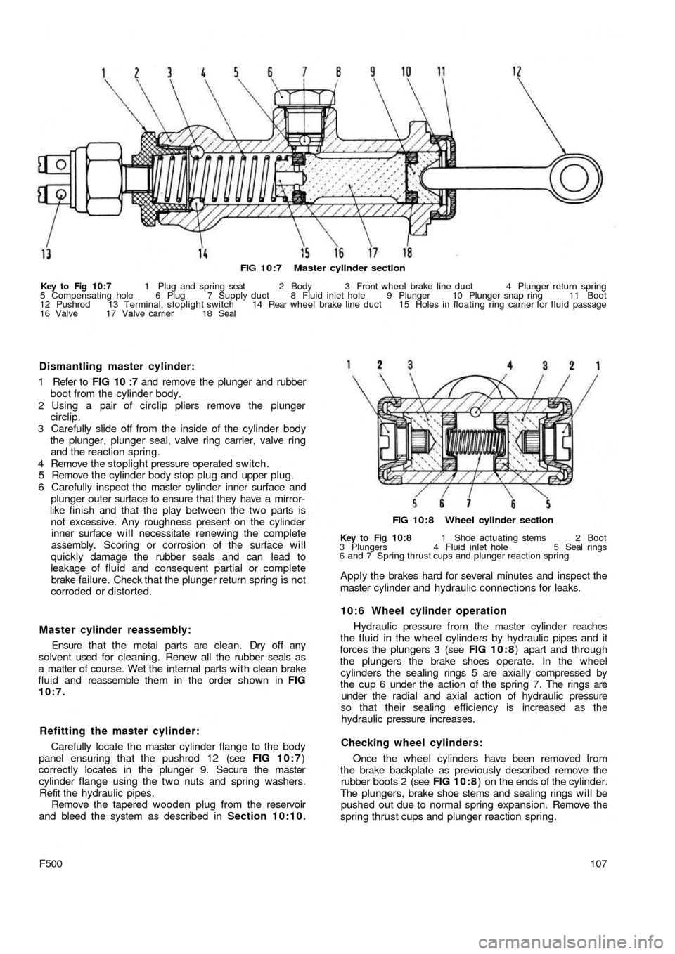
FIG 10:7 Master cylinder section
Key to Fig 10:7 1 Plug and spring seat 2 Body 3 Front wheel brake line duct 4 Plunger return spring
5 Compensating hole 6 Plug 7 Supply duct 8 Fluid inlet hole 9 Plunger 10 Plunger snap ring 11 Boot
12 Pushrod 13 Terminal, stoplight switch 14 Rear wheel brake line duct 15 Holes in floating ring carrier for fluid passage
16 Valve 17 Valve carrier 18 Seal
FIG 10:8 Wheel cylinder section
Key to Fig 10:8 1 Shoe actuating stems 2 Boot
3 Plungers 4 Fluid inlet hole 5 Seal rings
6 and 7 Spring thrust cups and plunger reaction spring
Apply the brakes hard for several minutes and inspect the
master cylinder and hydraulic connections for leaks.
10:6 Wheel cylinder operation
Hydraulic pressure from the master cylinder reaches
the fluid in the wheel cylinders by hydraulic pipes and it
forces the plungers 3 (see FIG 1 0 : 8) apart and through
the plungers the brake shoes operate. In the wheel
cylinders the sealing rings 5 are axially compressed by
the cup 6 under the action of the spring 7. The rings are
under the radial and axial action of hydraulic pressure
so that their sealing efficiency is increased as the
hydraulic pressure increases.
Checking wheel cylinders:
Once the wheel cylinders have been removed from
the brake backplate as previously described remove the
rubber boots 2 (see FIG 10:8) on the ends of the cylinder.
The plungers, brake shoe stems and sealing rings will be
pushed out due to normal spring expansion. Remove the
spring thrust cups and plunger reaction spring.
107F500
Master cylinder reassembly:
Ensure that the metal parts are clean. Dry off any
solvent used for cleaning. Renew all the rubber seals as
a matter of course. Wet the internal parts w i t h clean brake
fluid and reassemble them in the order shown in FIG
10:7.
Refitting the master cylinder:
Carefully locate the master cylinder flange to the body
panel ensuring that the pushrod 12 (see FIG 10:7)
correctly locates in the plunger 9. Secure the master
cylinder flange using the t w o nuts and spring washers.
Refit the hydraulic pipes.
Remove the tapered wooden plug from the reservoir
and bleed the system as described in Section 10:10. Dismantling master cylinder:
1 Refer to FIG 10 :7 and remove the plunger and rubber
boot from the cylinder body.
2 Using a pair of circlip pliers remove the plunger
circlip.
3 Carefully slide off from the inside of the cylinder body
the plunger, plunger seal, valve ring carrier, valve ring
and the reaction spring.
4 Remove the stoplight pressure operated switch.
5 Remove the cylinder body stop plug and upper plug.
6 Carefully inspect the master cylinder inner surface and
plunger outer surface to ensure that they have a mirror-
like finish and that the play between the two parts is
not excessive. Any roughness present on the cylinder
inner surface will necessitate renewing the complete
assembly. Scoring or corrosion of the surface will
quickly damage the rubber seals and can lead to
leakage of fluid and consequent partial or complete
brake failure. Check that the plunger return spring is not
corroded or distorted.