key FIAT 500 1971 1.G Workshop Manual
[x] Cancel search | Manufacturer: FIAT, Model Year: 1971, Model line: 500, Model: FIAT 500 1971 1.GPages: 128, PDF Size: 9.01 MB
Page 9 of 128
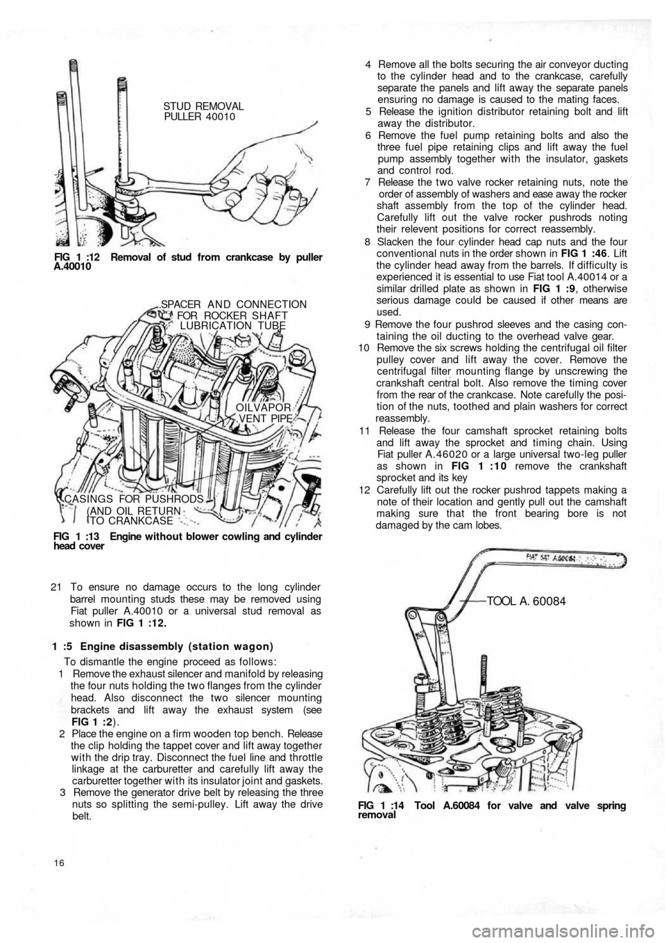
STUD REMOVAL
PULLER 40010
FIG 1 :12 Removal of stud from crankcase by puller
A.40010
FIG 1 :13 Engine without blower cowling and cylinder
head cover.SPACER A N D CONNECTION
FOR ROCKER SHAFT
LUBRICATION TUBE
OILVAPOR
.VENT PIPE
CASINGS FOR PUSHRODS
(AND OIL RETURN
TO CRANKCASE
21 To ensure no damage occurs to the long cylinder
barrel mounting studs these may be removed using
Fiat puller A.40010 or a universal stud removal as
shown in FIG 1 :12.
1 :5 Engine disassembly (station wagon)
To dismantle the engine proceed as follows:
1 Remove the exhaust silencer and manifold by releasing
the four nuts holding the two flanges from the cylinder
head. Also disconnect the two silencer mounting
brackets and lift away the exhaust system (see
FIG 1 : 2).
2 Place the engine on a firm wooden top bench. Release
the clip holding the tappet cover and lift away together
with the drip tray. Disconnect the fuel line and throttle
linkage at the carburetter and carefully lift away the
carburetter together with its insulator joint and gaskets.
3 Remove the generator drive belt by releasing the three
nuts so splitting the semi-pulley. Lift away the drive
belt.
16
FIG 1 :14 Tool A.60084 for valve and valve springremoval
TOOL A . 60084
4 Remove all the bolts securing the air conveyor ducting
to the cylinder head and to the crankcase, carefully
separate the panels and lift away the separate panels
ensuring no damage is caused to the mating faces.
5 Release the ignition distributor retaining bolt and lift
away the distributor.
6 Remove the fuel pump retaining bolts and also the
three fuel pipe retaining clips and lift away the fuel
pump assembly together with the insulator, gaskets
and control rod.
7 Release the t w o valve rocker retaining nuts, note the
order of assembly of washers and ease away the rocker
shaft assembly from the top of the cylinder head.
Carefully lift out the valve rocker pushrods noting
their relevent positions for correct reassembly.
8 Slacken the four cylinder head cap nuts and the four
conventional nuts in the order shown in FIG 1 :46. Lift
the cylinder head away from the barrels. If difficulty is
experienced it is essential to use Fiat tool A.40014 or a
similar drilled plate as shown in FIG 1 :9, otherwise
serious damage could be caused if other means are
used.
9 Remove the four pushrod sleeves and the casing con-
taining the oil ducting to the overhead valve gear.
10 Remove the six screws holding the centrifugal oil filter
pulley cover and lift away the cover. Remove the
centrifugal filter mounting flange by unscrewing the
crankshaft central bolt. Also remove the timing cover
f r o m t h e rear of t h e crankcase. Note carefully the posi-
tion of the nuts, toothed and plain washers for correct
reassembly.
11 Release the four camshaft sprocket retaining bolts
and lift away the sprocket and timing chain. Using
Fiat puller A.46020 or a large universal two-leg puller
as shown in FIG 1 : 1 0 remove the crankshaft
sprocket and its key
12 Carefully lift out the rocker pushrod tappets making a
note of their location and gently pull out the camshaft
making sure that the front bearing bore is not
damaged by the cam lobes.
Page 12 of 128
Cylinder head installation:
To refit the cylinder head proceed as follows:
Place a new cylinder head joint on the cleaned faces of
the cylinder barrels. Insert the rocker pushrod and
lubrication pipe sleeves together with the relevant
gaskets and rings.
Fit the washers and nuts to the studs and tighten to
fingertight.
Tighten the nuts in the order shown in FIG 1 :44 and
FIG 1 :46 to a torque wrench setting of 18.1 Ibft. Reset
the torque wrench to a new setting of 23.9 Ibft and
tighten the nuts once more in the recommended order.
Replace the pushrods in the correct order.
Refit the rocker shaft ensuring correct location of the
lubrication tube to the rocker shaft and replace the
plain and lockwashers. Tighten the nuts to a torque
wrench setting of 15.2 Ibft. Reset the tappet to rocker
clearance adjustment.
Connect the t w o exhaust side manifolds to the cylinder
head. Using new gasket refit the spark plugs and HT
cables. Replace the rocker cover fitted with a new cork
gasket and blower conveyor to the cylinder head
securing screws. Refit the carburetter and reconnect its
fuel line and controls. Refit the air cleaner and elbow
and connect the rocker cover breather pipe (if fitted).
1
2
3
4
5
1 :7 Timing gear overhaul
Camshaft:
The cast iron camshaft is located in the crankcase and is
supported at either end in sets machined directly in the
crankcase. No bushes are used. The camshaft is driven by
a chain from the crankshaft at half engine speed and
operates the overhead valves through tappets, pushrods
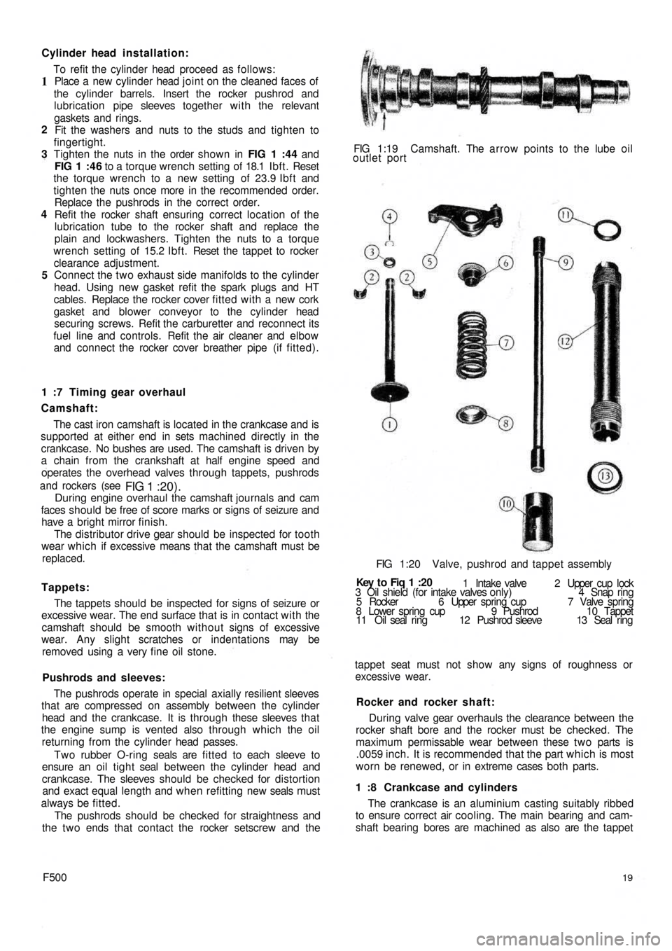
and rockers (see
FIG 1 :20).During engine overhaul the camshaft journals and cam
faces should be free of score marks or signs of seizure and
have a bright mirror finish.
The distributor drive gear should be inspected for tooth
wear which if excessive means that the camshaft must be
replaced.
Tappets:
The tappets should be inspected for signs of seizure or
excessive wear. The end surface that is in contact with the
camshaft should be smooth without signs of excessive
wear. Any slight scratches or indentations may be
removed using a very fine oil stone.
Pushrods and sleeves:
The pushrods operate in special axially resilient sleeves
that are compressed on assembly between the cylinder
head and the crankcase. It is through these sleeves that
the engine sump is vented also through which the oil
returning from the cylinder head passes.
Two rubber O-ring seals are fitted to each sleeve to
ensure an oil t i g h t seal between the cylinder head and
crankcase. The sleeves should be checked for distortion
and exact equal length and when refitting new seals must
always be fitted.
The pushrods should be checked for straightness and
the t w o ends that contact the rocker setscrew and the
F50019
The crankcase is an aluminium casting suitably ribbed
to ensure correct air cooling. The main bearing and cam-
shaft bearing bores are machined as also are the tappet 1 :8 Crankcase and cylinders During valve gear overhauls the clearance between the
rocker shaft bore and the rocker must be checked. The
maximum permissable wear between these t w o parts is
.0059 inch. It is recommended that the part which is most
worn be renewed, or in extreme cases both parts. Rocker and rocker shaft: tappet seat must not show any signs of roughness or
excessive wear. 3 Oil shield (for intake valves only) 4 Snap ring
5 Rocker 6 Upper spring cup 7 Valve spring
8 Lower spring cup 9 Pushrod 10 Tappet
11 Oil seal ring 12 Pushrod sleeve 13 Seal ring 1 Intake valve 2 Upper cup lock Key t o Fiq
1 :20 FIG 1:20 Valve, pushrod and tappet assembly FIG 1:19 Camshaft. The arrow points to the lube oil
outlet port
Page 18 of 128
After the crankshaft has been reground it is important
that all traces of swarf are removed by constant washing
and then drying with a non-fluffy rag.
The clearance between the main bearings and journals
must be checked before installing the crankshaft in the
engine. It should also serve as a recheck after the
crankshaft has been reground.
Measure the maximum main bearing internal
diameter and the minimum journal diameter using
accurate measuring equipment. The clearance must not
exceed .0039 inch otherwise the journals must be
reground and undersize bearings fitted.
Undersize bearings w i t h .0394 inch stock on the
internal diameter are also supplied unmounted. They
must be press fitted in the supports, the recommended
interference fit being .00039 to .00197 inch. After
pressing the bearing into the support, a hole is drilled in
the bearing in line with the location dowel hole in the
support. The hole is finished with a suitable expanding
reamer, such as Fiat U.0334, and the dowel pressed i n ,
noting that the hollow dowel fits in the flywheel end
support.
The next stage is to heat the assembly in an oven or
oil bath for a period of one hour at 150°C (302°F).
When the assembly has cooled to room temperature,
the bearing is reamed in a lathe to match the crankshaft
journal size.
3
Crankshaft oil seals:
Two inner spring rubber oil seals are located, one in a
special seat in the timing gear cover and the other in the
flywheel end of the crankshaft support and provide oil
tightness. These seals are shown in FIGS 1 :3 and 1 :34.
Whenever the engine is dismantled for overhaul these
seals should be carefully inspected for correct seating and
that the inner seal surface is not worn and that the contact
area is perfect both on the crankshaft and on the fan and
generator drive pulley hub.
Clutch shaft pilot bushing:
A self-lubricating bronze bush is fitted in the end of the
crankshaft as shown in FIG 1 :34 and provides a bearing
for the clutch shaft. Should the bush be worn use Fiat
puller A.40006/1 /2 to remove the worn bush. A new bush
should be fitted using a suitably sized drift.
1:12 Flywheel and starter ring gear
The flywheel should be inspected for wear at the clutch
driven plate contact area. It should be flat and have a
smooth finish.
The ring gear teeth should be cheeked for damage
which if evident, the ring gear must be replaced. To facili-
tate the fitting of a new ring gear on the flywheel, the new
ring gear should be heated in an oil bath to a temperature
of 80°C (176°F). Using a press gently ease the
expanded
ring gear over the flywheel and press fully home.
1:13 The oil pump
Sedan :
A helical-spur gear type oil pump is driven by the cam-
shaft through a front dog drive coupling. The gears are
F50025 To remove the pump from the engine proceed as
follows:Pump removal and reassembly:
Remove the engine rear central support from the timing
gear casing. Remove the filter cover pulley and lift
away the drive belt.
Release the hollow screw attaching the slinger and the
mounting flange of the filter on the crankshaft. Also
release the nuts fixing the timing gear cover to the
crankcase.
Remove the timing gear cover together with the oil
pump assembly and the pressure relief valve.
Lift out the oil pump suction scoop with the filter
screen attached from the sump.
Reassembly of the pump to the engine is the reverse
procedure to dismantling. 1
2
3
4
5 located in a special housing in the timing gear cover and
held in place by a cover plate. The oil pressure relief valve
is mounted on the drive gear shaft guide.
A pump suction scoop fitted with a filter screen is
secured in the crankcase and connects to a duct in the
timing gear case as s h o w n in FIG 1 :36.
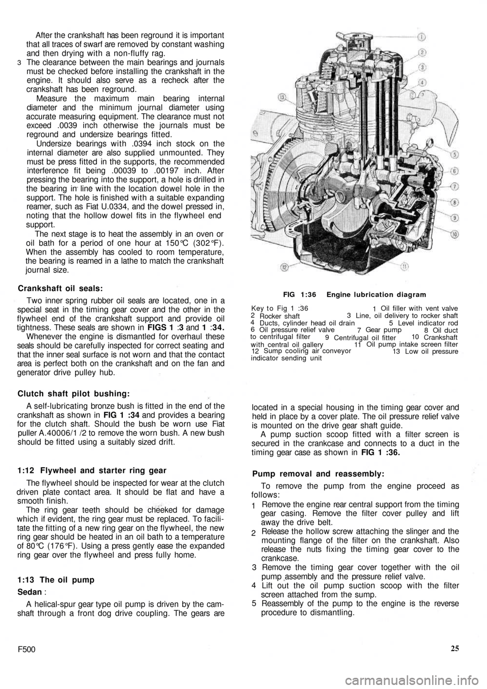
2
4
6Key t o Fig 1 :36
Rocker shaft
Ducts, cylinder head oil drain
Oil pressure relief valve
to centrifugal filter
9
with central oil gallery
12Sump cooling air conveyor
indicator sending unitOil filler with vent valve
Line, oil delivery to rocker shaft
Level indicator rod 31
5
7Gear pump
8 Oil duct
Centrifugal oil fitter
1110
Crankshaft
Oil pump intake screen filter
13 Low oil pressure FIG 1:36 Engine lubrication diagram
Page 19 of 128
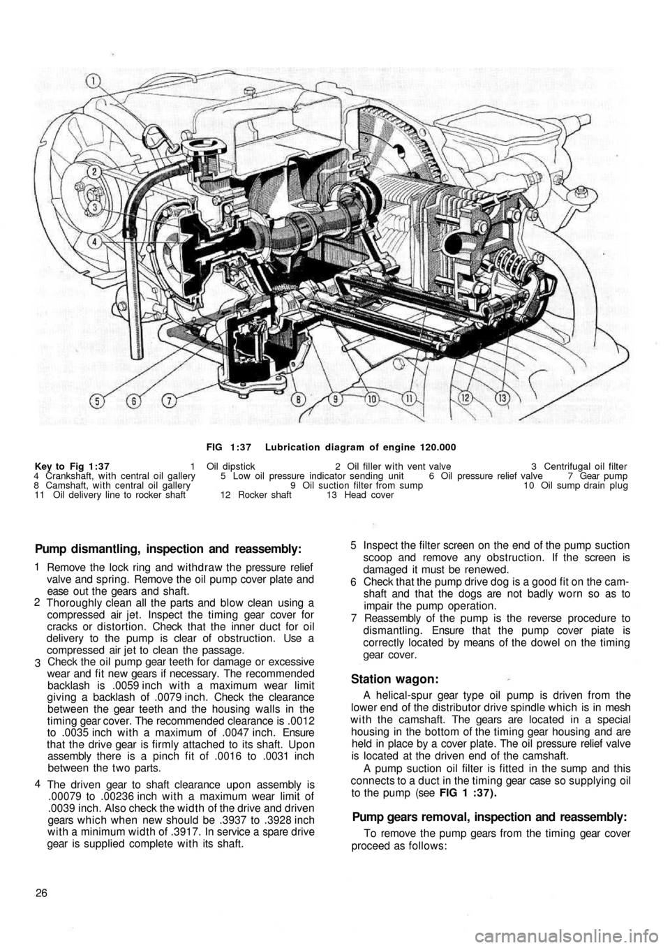
FIG 1:37 Lubrication diagram of engine 120.000
Key to Fig 1:37 1 Oil dipstick 2 Oil filler with vent valve 3 Centrifugal oil filter
4 Crankshaft, with central oil gallery 5 Low oil pressure indicator sending unit 6 Oil pressure relief valve 7 Gear pump
8 Camshaft, with central oil gallery 9 Oil suction filter from sump 10 Oil sump drain plug
11 Oil delivery line to rocker shaft 12 Rocker shaft 13 Head cover
Pump dismantling, inspection and reassembly:
Remove the lock ring and withdraw the pressure relief
valve and spring. Remove the oil pump cover plate and
ease o u t t h e gears and shaft.
Thoroughly clean all the parts and blow clean using a
compressed air jet. Inspect the timing gear cover for
cracks or distortion. Check that the inner duct for oil
delivery to the pump is clear of obstruction. Use a
compressed air jet to clean the passage.
Check the oil pump gear teeth for damage or excessive
wear and fit new gears if necessary. The recommended
backlash is .0059 inch w i t h a maximum wear limit
giving a backlash of .0079 inch. Check the clearance
between the gear teeth and the housing walls in the
timing gear cover. The recommended clearance is .0012
to .0035 inch w i t h a maximum of .0047 inch. Ensure
that the drive gear is firmly attached to its shaft. Upon
assembly there is a pinch fit of .0016 to .0031 inch
between the t w o parts.
The driven gear to shaft clearance upon assembly is
.00079 to .00236 inch with a maximum wear limit of
.0039 inch. Also check the width of the drive and driven
gears which when new should be .3937 to .3928 inch
with a minimum width of .3917. In service a spare drive
gear is supplied complete with its shaft.
26 4 3 2 1
Station wagon:
A helical-spur gear type oil pump is driven from the
lower end of the distributor drive spindle which is in mesh
w i t h the camshaft. The gears are located in a special
housing in the bottom of the timing gear housing and are
held in place by a cover plate. The oil pressure relief valve
is located at the driven end of the camshaft.
A pump suction oil filter is fitted in the sump and this
connects to a duct in the timing gear case so supplying oil
to the pump (see FIG 1 : 3 7 ) .
Pump gears removal, inspection and reassembly:
To remove the pump gears from the timing gear cover
proceed as follows:Inspect the filter screen on the end of the pump suction
scoop and remove any obstruction. If the screen is
damaged it must be renewed.
Check that the pump drive dog is a good fit on the cam-
shaft and that the dogs are not badly worn so as to
impair the pump operation.
Reassembly of the pump is the reverse procedure to
dismantling. Ensure that the pump cover piate is
correctly located by means of the dowel on the timing
gear cover. 5
6
7
Page 20 of 128
Drain the oil sump to ensure that the oil does not syphon
out. Thoroughly clean the area around the pump body
(see FIG 1 :37).
Remove the end cover plate by releasing the retaining
bolts and washers. Carefully ease t h e driven gear down-
wards followed by the driving gear and shaft
Clean all parts removed and blow clean using a com-
pressed air jet. Inspect the timing gear cover pump area
for cracks or distortion. Check that the inner duct for oil
delivery to the pump is clear of obstruction. If in doubt
remove the drain plug and filler cap and use a com-
pressed air j e t to clean the passage.
Check the gear teeth for damage or excessive wear,
ensure that the drive gear is firmly attached to its spindle
and that the end cover plate is not badly scored or pitted.
Fit new parts as necessary.
Reassembly is the reverse procedure to dismantling,
taking care that all parts are assembled clean and the
end cover plate seating correctly with a new gasket. 5 43 21
1:14 Lubrication, oil filter, relief valve
Description :
The engine is pressure lubricated through a gear type
pump which is incorporated in the timing gear cover and
driven from the camshaft by dogs or gears. The lubrication
circuits are shown in FIGS 1 :36 and 1 : 37.
The pump draws oil from the sump through a suction
horn fitted with a filter screen which is fixed to the crank-
case by a d u c t in t h e timing gear cover. This
supplies oil
to the pump.
Oil passes f r o m the camshaft rear seat o n t o t h e crank-
shaft rear support where it flows into an adjacent chamber.
From here the o i l flows through ducts in the crankshaft
from end to the centrifugal oil filter. The centrifugal filter,
which also acts as a pulley for the generator and blower
drive, rotates w i t h the crankshaft.
Oil from the filter enters a passage in the crankshaft,
where it lubricates the main and connecting rod bearings
and passes f r o m a special groove in the front main
bearing and ducting in the crankcase into which is
inserted the oil pressure warning sender unit, and also
the delivery pipe for oil to the overhead valve gear.
The pushrod sleeves provide the return path for the oil
from the cylinder head and delivers oil to the tappet gear
and the camshaft cams. The tappets are suitably drilled
to allow correct circulation of the oil. The tappets are
located in t w o casting cavities, one of which com-
municates w i t h the timing gear housing and the other
one to the crankshaft front drain support drain.
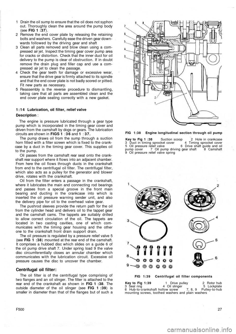
The oil pressure is regulated by a pressure relief valve 5
(see FIG 1 : 3 8) mounted at the rear end of t h e camshaft.
It comprises a hubbed disc which slides on a guide 6 of
the oil pump drive shaft 7. Under spring load 9 the valve
disc circumferentially closes an annular chamber which
communicates w i t h the lubrication circuit. Excessive o i l
pressure causes the disc to uncover the chamber.
Centrifugal oil filter:
The oil filter is of the centrifugal type comprising of
two flanges and an oil slinger. The filter is attached to the
rear end o f t h e c r a n k s h a f t a s s h o w n i n FIG 1 :38. The
outside diameter of the oil slinger (see FIG 1 :39) is
smaller in diameter than that of the flanges but of such a
F50027
Key to Fig 1:39 1 Drive pulley 2 Rotor hub
3 Seal ring 4 Oil slinger 5 Lockplate
6 Hub-to-crankshaft hollow screw 7, 8, 9 Pulley-to-hub
mounting screws, toothed washers and plain washers FIG 1:39 Centrifugal oil filter components Key to Fig 1 :38 Suction scoop 2 Hole in crankcase
3 Duct in timing sprocket cover 4 Timing sprocket cover
5 Oil pressure relief valve 6 Drive shaft guide and oil
pump cover 7 Oil pump driving gear shaft 8 Camshaft
9 Oil pressure relief valve spring FIG 1:38 Engine longitudinal section through oil pump
Page 21 of 128
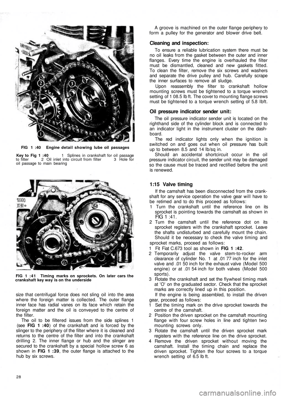
FIG 1 :40 Engine detail showing lube oil passages
Key to Fig 1 :40 1 Splines in crankshaft for oil passage
to filter 2 Oil inlet into circuit from filter 3 Hole for
oil passage to main bearing
FIG 1 : 4 1 Timing marks on sprockets. On later cars the
crankshaft key way is on the underside
size that centrifugal force does not sling oil into the area
where the foreign matter is collected. The outer flange
inner face has radial vanes on its face which retain the
foreign matter and the oil is conveyed to the centre of
the filter.
The oil to be filtered issues from the side splines 1
(see FIG 1 :40) of the crankshaft and is forced by the
slinger to the periphery of the filter where it is cleaned and
returns to the centre of the filter and into the crankshaft
drilling 2. The inner flange or hub and the slinger are
secured to the crankshaft by a special hollow screw 6 as
shown in FIG 1 :39, the outer flange is attached to the
hub by six screws.
28
If the camshaft has been disconnected from the crank-
shaft for any service operation the valve gear will have to
be retimed and to do this proceed as follows:
1 Turn the crankshaft until the reference line on its
sprocket is pointing towards the camshaft as shown in
FIG 1 :41.
2 Turn the camshaft until the reference dot on its
sprocket registers w i t h the crankshaft sprocket. Leave
the shafts undisturbed and carefully mount the chain.
Should it be necessary to check the valve timing and
sprocket marks, proceed as follows:
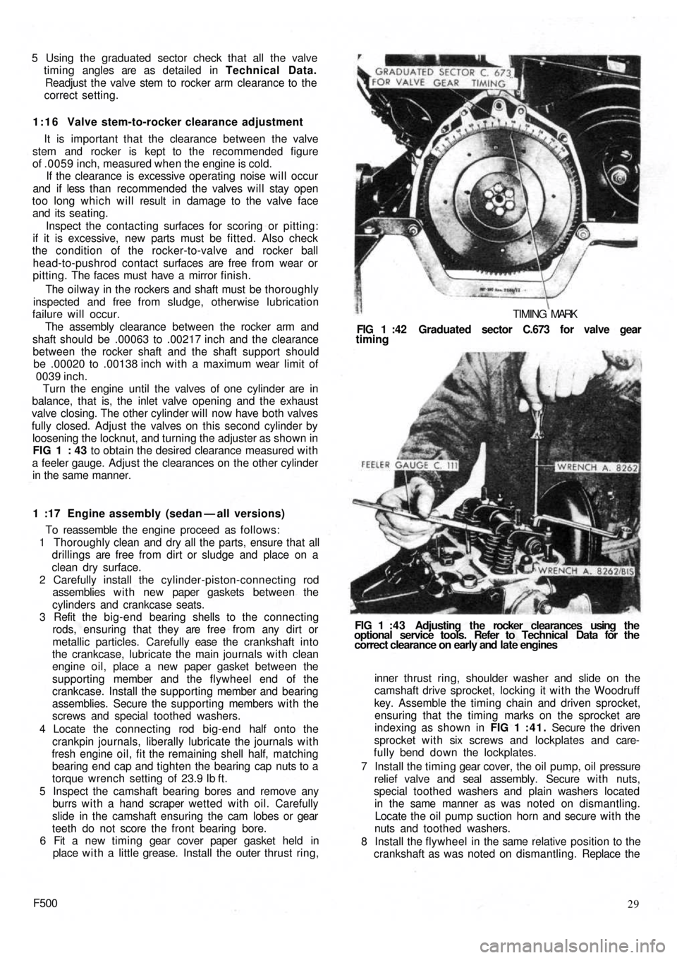
1 Fit Fiat C.673 tool as shown in FIG 1 :42.
2 Temporarily adjust the valve stem-to-rocker arm
clearance of cylinder No. 1 at .01 77 inch for the inlet
valve and .01 50 inch for the exhaust valve (Model 500
engine) or at .01 54 inch for both valves (Model 500
sports).
3 Rotate the crankshaft and set the flywheel timing mark
at 'O' on the graduated sector. Check that the sprocket
marks are correctly lined up in this position.
If the engine is being assembled, to install the driven
gear, proceed as follows:
1 Set the timing mark on the drive sprocket towards the
centre of the camshaft.
2 Position the driven sprocket on the camshaft mounting
flange with four screw holes in line and tighten two
mounting screws only.
3 Rotate the camshaft until the driven sprocket mark
registers w i t h the reference line on the drive sprocket.
4 Remove the driven sprocket without moving the
camshaft. Install the timing chain and replace the
driven sprocket. Tighten the four screws to a torque
wrench setting of 6.5 Ib ft.
1:15 Valve timing
The oil pressure indicator sender unit is located on the
righthand side of the cylinder block and is connected to
an indicator light in the instrument cluster on the dash-
board.
The red indicator lights only when the ignition is
switched on and goes out when o i l pressure has built
up to between 8.5 and 14 Ib/sq in.
Should an accidental shortcircuit occur in the oil
pressure indicator circuit, the sender unit may be damaged
so the cause must be traced and rectified before the unit
is renewed.
Oil pressure indicator sender unit:
To ensure a reliable lubrication system there must be
no oil leaks from the gasket between the outer and inner
flanges. Every t i m e t h e engine is overhauled the filter
must be dismantled, cleaned and new gaskets fitted.
To clean the filter, remove the six screws and washers
and separate the drive pulley and hub. Carefully scrape
the inner surfaces to remove all sludge.
Upon reassembly the filter to crankshaft hollow
mounting screws must be tightened to a torque wrench
setting of 1 08.5 Ib ft. The cover to mounting flange screws
must be tightened to a torque wrench setting of 5.8 Ibft.
Cleaning and inspection:
A groove is machined on the outer flange periphery to
form a pulley for the generator and blower drive belt.
Page 22 of 128
5 Using the graduated sector check that all the valve
timing angles are as detailed in Technical Data.
Readjust the valve stem to rocker arm clearance to the
correct setting.
1:16 Valve stem-to-rocker clearance adjustment
It is important that the clearance between the valve
stem and rocker is kept to the recommended figure
of .0059 inch, measured when the engine is cold.
If the clearance is excessive operating noise will occur
and if less than recommended the valves will stay open
too long which will result in damage to the valve face
and its seating.
Inspect the contacting surfaces for scoring or pitting:
if it is excessive, new parts must be fitted. Also check
the condition of the rocker-to-valve and rocker ball
head-to-pushrod contact surfaces are free from wear or
pitting. The faces must have a mirror finish.
The oilway in the rockers and shaft must be thoroughly
inspected and free from sludge, otherwise lubrication
failure will occur.
The assembly clearance between the rocker arm and
shaft should be .00063 to .00217 inch and the clearance
between the rocker shaft and the shaft support should
be .00020 to .00138 inch with a maximum wear limit of
0039 inch.
Turn the engine until the valves of one cylinder are in
balance, that is, the inlet valve opening and the exhaust
valve closing. The other cylinder will now have both valves
fully closed. Adjust the valves on this second cylinder by
loosening the locknut, and turning the
adjuster as shown in
FIG 1 : 43 to obtain the desired clearance measured with
a feeler gauge. Adjust the clearances on the other cylinder
in the same manner.
1 :17 Engine assembly (sedan — all versions)
To reassemble the engine proceed as follows:
1 Thoroughly clean and dry all the parts, ensure that all
drillings are free from dirt or sludge and place on a
clean dry surface.
2 Carefully install the cylinder-piston-connecting rod
assemblies w i t h new paper gaskets between the
cylinders and crankcase seats.
3 Refit the big-end bearing shells to the connecting
rods, ensuring that they are free from any dirt or
metallic particles. Carefully ease t h e crankshaft into
the crankcase, lubricate the main journals with clean
engine oil, place a new paper gasket between the
supporting member and the flywheel end of the
crankcase. Install the supporting member and bearing
assemblies. Secure the supporting members with the
screws and special toothed washers.
4 Locate the connecting rod big-end half onto the
crankpin journals, liberally lubricate the journals with
fresh engine oil, fit the remaining shell half, matching
bearing end cap and tighten the bearing cap nuts to a
torque wrench setting of 23.9 Ib ft.
5 Inspect the camshaft bearing bores and remove any
burrs w i t h a hand scraper wetted with oil. Carefully
slide in the camshaft ensuring the cam lobes or gear
teeth do not score the front bearing bore.
6 Fit a new timing gear cover paper gasket held in
place w i t h a little grease. Install the outer thrust ring,
F50029 inner thrust ring, shoulder washer and slide on the
camshaft drive sprocket, locking it with the Woodruff
key. Assemble the timing chain and driven sprocket,
ensuring that the timing marks on the sprocket are
indexing as shown in FIG 1 :41. Secure the driven
sprocket with six screws and lockplates and care-
fully bend down the lockplates.
7 Install the timing gear cover, the oil pump, oil pressure
relief valve and seal assembly. Secure w i t h nuts,
special toothed washers and plain washers located
in the same manner as was noted on dismantling.
Locate the oil pump suction horn and secure with the
nuts and toothed washers.
8 Install the flywheel in the same relative position to the
crankshaft as was noted on dismantling. Replace the FIG 1 : 4 3 Adjusting the rocker clearances using the
optional service tools. Refer to Technical Data for the
correct clearance on early and late engines FIG 1 :42 Graduated sector C.673 for valve gear
timing
TIMING MARK
Page 24 of 128
sections of the air conveyor securing with seven
screws, seven toothed washers and five nuts.
22 Slide the fuel pump control rod into its seating,
assemble the insulator between oil wetted graphite
gaskets and fit the pump to the crankcase using nuts
and toothed washers.
23 Fit the air conveyor cover complete with the accelera-
tor control relay lever and rod. Secure using eight
mounting screws, eight toothed washers, eight plain
washers and eight nuts. Fit the fuel line retaining clip
which is secured by one of the air conveyor upper
screws. Install the generator and fan drive pulley
having first placed four adjusting rings between the
pulley halves and the thrust ring on the outside.
Secure the pulley to generator shaft using three
screws and three toothed washers. Fit the generator
fan drive belt.
24 Refit the carburetter having first positioned the
bakelite heat shield between the t w o oil moistened
graphite gaskets. Secure the carburetter using t w o
copper washers and t w o self-locking nuts. Fit the
exhaust silencer and secure to the exhaust manifolds
with nuts and spring washers. Place the t w o graphite
gaskets between the manifold joints. Fit both exhaust
silencer upper mounting brackets and secure them
on the top side to the brackets already in place w i t h
nuts and toothed washers on the bottom side w i t h
screws and toothed washers.
25 Carefully position the distributor at a 10 deg advance
setting and secure w i t h a
nut, plain washer and
spring washer. Fit the fuel pump to carburetter line
complete w i t h mounting bracket rubber lining and
secure the line with two clamps. If difficulty is
experienced in positioning the fuel line into the pump
or carburetter funnels it is suggested that the line
ends should be heated in hot water and thoroughly
dried before installing.
26 Install the air cleaner elbow and rubber hose assembly
on the top of the carburetter using a graphite gasket
in between and secure w i t h nuts, plain washers and
spring washers. Carefully position the air cleaner, line
and hose assembly and connect it to the elbow.
Secure the cleaner to air conveyor cover using screws
and toothed washers.
27 Fit the spark plug cables complete with the rubber
grommet for cable mounting bracket on engine
cowling and connect the cables to the distributor
and spark plugs. Fit the oil pressure gauge sender
unit together w i t h its sealing washer.
28 Install the cylinder head cover and oil breather pipe
assembly w i t h a cork gasket inserted between.
Secure w i t h self-locking nuts and fibre washers.
Connect the accelerator control relay lever rod to the
carburetter and secure with the clip.
29 Fill the oil pan with the correct grade and quantity of
oil, insert the dipstick and the engine is ready for
refitting.
1:18 Engine assembly (station wagon)
Reassembly of this engine is straightforward as it is
the reverse procedure to dismantling. It is recommended
that Sections 1 :5 and 1 :17 are studied as the assembly
technique is similar for both the horizontal and vertical
F50031 cylinder engines. The following points should however
be noted:
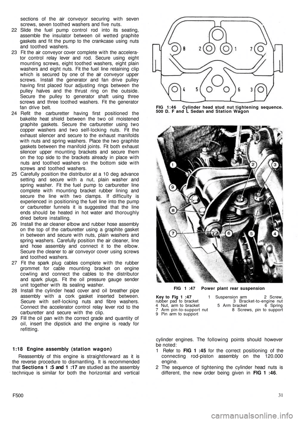
1 Refer to FIG 1 :45 for the correct positioning of the
connecting rod-piston assembly on the 120.000
engine.
2 The sequence of tightening the cylinder head nuts is
different, the new order being given in FIG 1 :46.
Key to Fig 1 :47 1 Suspension arm 2 Screw,
rubber pad to bracket 3 Bracket-to-engine nut
4 Nut, arm to bracket 5 Arm bracket 6 Spring
7 Arm pin-to-support nut 8 Screws, pin to support
9 Pin arm to supportFIG 1 :47 Power plant rear suspension FIG 1:46 Cylinder head stud nut tightening sequence.
500 D. F and L Sedan and Station Wagon
Page 25 of 128
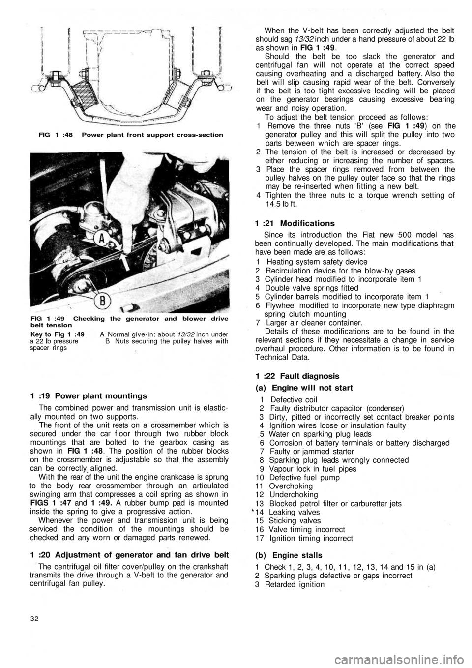
FIG 1 :48 Power plant front support cross-section
FIG 1 :49 Checking the generator and blower drive
belt tension
1 :19 Power plant mountings
The combined power and transmission unit is elastic-
ally mounted on two supports.
The front of the unit rests on a crossmember which is
secured under the car floor through two rubber block
mountings that are bolted to the gearbox casing as
shown in FIG 1 :48. The position of the rubber blocks
on the crossmember is adjustable so that the assembly
can be correctly aligned.
W i t h t h e rear of the unit the engine crankcase is sprung
to the b o d y rear crossmember through an articulated
swinging arm that compresses a coil spring as shown in
FIGS 1 :47 and 1 :49. A rubber bump pad is mounted
inside the spring to give a progressive action.
Whenever the power and transmission unit is being
serviced the condition of the mountings should be
checked and any worn or damaged parts renewed.
1 :20 Adjustment of generator and fan drive belt
The centrifugal oil filter cover/pulley on the crankshaft
transmits the drive through a V-belt to the generator and
centrifugal fan pulley.
32
(b) Engine stalls
1 Check 1, 2, 3, 4, 10, 1 1 , 12, 13, 14 and 15 in (a)
2 Sparking plugs defective or gaps incorrect
3 Retarded ignition 1 Defective coil
2 Faulty distributor capacitor (condenser)
3 Dirty, pitted or incorrectly set contact breaker points
4 Ignition wires loose or insulation faulty
5 Water on sparking plug leads
6 Corrosion of battery terminals or battery discharged
7 Faulty or jammed starter
8 Sparking plug leads wrongly connected
9 Vapour lock in fuel pipes
10 Defective fuel pump
11 Overchoking
12 Underchoking
13 Blocked petrol filter or carburetter jets
14 Leaking valves
15 Sticking valves
16 Valve timing incorrect
17 Ignition timing incorrect
(a) Engine will not start 1 :22 Fault diagnosis
Since its introduction the Fiat new 5 0 0 model has
been continually developed. The main modifications that
have been made are as follows:
1 Heating system safety device
2 Recirculation device for the blow-by gases
3 Cylinder head modified to incorporate item 1
4 Double valve springs fitted
5 Cylinder barrels modified to incorporate item 1
6 Flywheel modified to incorporate new type diaphragm
spring clutch mounting
7 Larger air cleaner container.
Details of these modifications are to be found in the
relevant sections if they necessitate a change in service
overhaul procedure. Other information is to be found in
Technical Data.
1 :21 Modifications
When the V-belt has been correctly adjusted the belt
should sag 13/32 inch under a hand pressure of about 22 lb
as shown in FIG 1 : 4 9.
Should the belt be too slack the generator and
centrifugal fan will not operate at the correct speed
causing overheating and a discharged battery. Also the
belt will slip causing rapid wear of the belt. Conversely
if the belt is too tight excessive loading will be placed
on the generator bearings causing excessive bearing
wear and noisy operation.
To adjust the belt tension proceed as follows:
1 Remove the three nuts ' B ' (see FIG 1 :49) on the
generator pulley and this will split the pulley into two
parts between which are spacer rings.
2 The tension of the belt is increased or decreased by
either reducing or increasing the number of spacers.
3 Place the spacer rings removed from between the
pulley halves on the pulley outer face so that the rings
may be re-inserted when fitting a new belt.
4 Tighten the three nuts to a torque wrench setting of
14.5
lb ft.
Key to Fig 1 :49 A Normal give-in: about 13/32 inch under
a 22 Ib pressure B Nuts securing the pulley halves with
spacer rings
Page 29 of 128
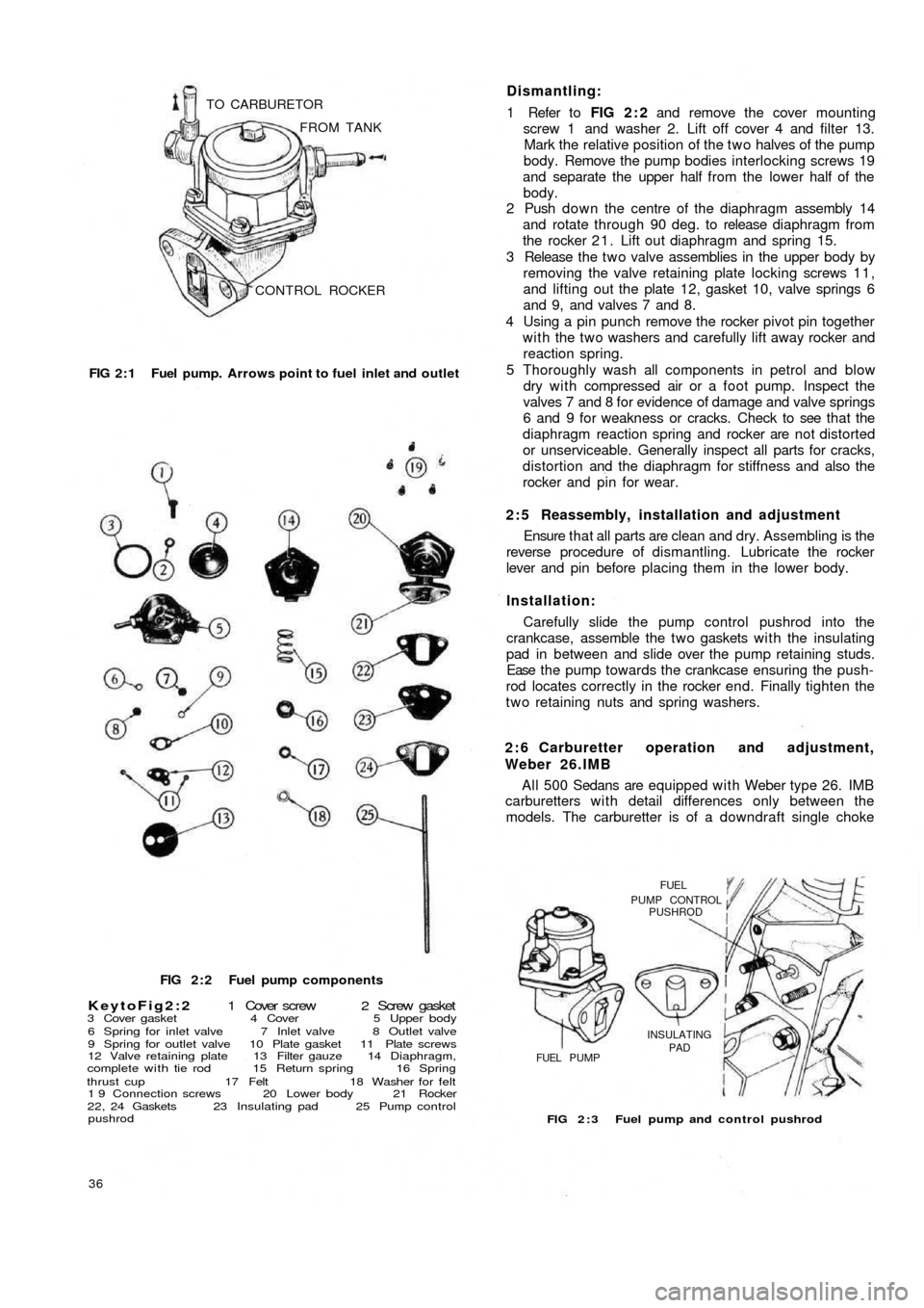
CONTROL ROCKER FROM TANK TO CARBURETOR
FIG 2 : 1 Fuel pump. Arrows point to fuel inlet and outlet
FIG 2 : 2 Fuel pump components
KeytoFig2:2 1 Cover screw 2 Screw gasket3 Cover gasket 4 Cover 5 Upper body
6 Spring for inlet valve 7 Inlet valve 8 Outlet valve
9 Spring for outlet valve 10 Plate gasket 11 Plate screws
12 Valve retaining plate 13 Filter gauze 14 Diaphragm,
complete with tie rod 15 Return spring 16 Spring
thrust cup 17 Felt 18 Washer for felt
1 9 Connection screws 20 Lower body 21 Rocker
22, 24 Gaskets 23 Insulating pad 25 Pump control
pushrod
36
FIG 2 : 3 Fuel pump and control pushrod
FUELPUMP CONTROLPUSHROD
INSULATING
PAD
FUEL PUMP
A l l 500 Sedans are equipped with Weber type 26. IMB
carburetters w i t h detail differences only between the
models. The carburetter is of a downdraft single choke 2 : 6 Carburetter operation and adjustment,
Weber 26.IMB Carefully slide the pump control pushrod into the
crankcase, assemble the t w o gaskets w i t h the insulating
pad in between and slide over the pump retaining studs.
Ease t h e p u m p towards the crankcase ensuring the push-
rod locates correctly in the rocker end. Finally tighten the
two retaining nuts and spring washers. Installation:Ensure t h a t all parts are clean and dry. Assembling is the
reverse procedure of dismantling. Lubricate the rocker
lever and pin before placing them in the lower body. 2 : 5 Reassembly, installation and adjustment 1 Refer to FIG 2 : 2 and remove the cover mounting
screw 1 and washer 2. Lift off cover 4 and filter 13.
Mark the relative position of the two halves of the pump
body. Remove the pump bodies interlocking screws 19
and separate the upper half from the lower half of the
body.
2 Push down the centre of the diaphragm assembly 14
and rotate through 90 deg. to release diaphragm from
the rocker 2 1 . Lift out diaphragm and spring 15.
3 Release the t w o valve assemblies in the upper body by
removing the valve retaining plate locking screws 1 1 ,
and lifting out the plate 12, gasket 10, valve springs 6
and 9, and valves 7 and 8.
4 Using a pin punch remove the rocker pivot pin together
w i t h the t w o washers and carefully lift away rocker and
reaction spring.
5 Thoroughly wash all components in petrol and
blow
dry with compressed air or a foot pump. Inspect the
valves 7 and 8 for evidence of damage and valve springs
6 and 9 for weakness or cracks. Check to see that the
diaphragm reaction spring and rocker are not distorted
or unserviceable. Generally inspect all parts for cracks,
distortion and the diaphragm for stiffness and also the
rocker and pin for wear. Dismantling: