chapter FIAT 500 1972 1.G Workshop Manual
[x] Cancel search | Manufacturer: FIAT, Model Year: 1972, Model line: 500, Model: FIAT 500 1972 1.GPages: 128, PDF Size: 9.01 MB
Page 2 of 128
CHAPTER 1
THE ENGINE
1 :1
1 :2
1 :3
1 :4
1 :5
1 :6
1 :7
1 :8
1:9
1 :10
1 :11Description
Engine removal (sedan—all versions)
Engine removal (station wagon)
Engine disassembly (sedan—all versions)
Engine disassembly (station wagon)
Cylinder head removal, servicing and
replacement
Timing gear overhaul
Crankcase and cylinders
Piston assembly
Connecting rods
Crankshaft and main bearings
1 :1 Description
The 'New 500' two-cylinder aircooled engine operates
on the four-stroke 'Otto Cycle' and is fitted directly to
the transmission unit which incorporates the rear drive
assembly as shown in FIG 1 :1 and FIG 1 :2.
With the power unit fitted at the rear several advantages
are obtained including better load distribution to the
wheels when the vehicle is loaded, elimination of propeller
shaft reducing the size of centre tunnel and better use of
available space.
The cylinder block comprises t w o cast iron cylinder
barrels w i t h cooling fins. The bottom of the cylinders fit
into machined seats in the aluminium crankcase.
The aluminium crankcase carries eight studs on which
are located the t w o cylinder barrels w i t h the aluminium
cylinder head on the top.
A two bush crankshaft of special cast iron is fitted into
the lower half of the crankcase. The crankshaft is
F5009 provided with a counterweight and is hollow to allow for
lubrication.
The steel connecting rods have thin wall bearing halves
on the big-end, and bronze bushes in the small-end. The
offset piston pin is of steel and retained in the piston by
two circlips.
Light alloy pistons are used and are of the taper-oval-
shaped type with a maximum diameter at the base of the
skirt, along an axis perpendicular to the piston pin. Pistons
are fitted with four rings as follows, one compression at
the top, two standard oil scraper rings and one side slotted
oil scraper ring.
The one-piece aluminium cylinder head is finned to
provide a larger cooling surface and carries the inlet and
exhaust manifolds.
The inlet passages merge into a single centralized
flange onto which is mounted the carburetter. The exhaust
passages run almost parallel to the axis of the engine. 1 :12
1 :13
1 :14
1 :15
1 :16
1 :17
1 :18
1 :19
1 :20
1 :21
1 :22Flywheel and starter ring gear
The oil pump
Lubrication, oil filter, relief valve
Valve timing
Valve stem to rocker clearance
Engine assembly (sedan—all versions)
Engine assembly (station wagon)
Power plant mounting
Adjustment of generator and fan belt drive
Modifications
Fault diagnosis
Page 15 of 128
FEELER GAUGE
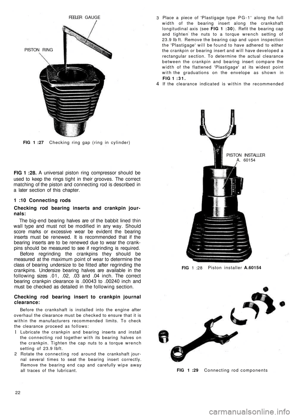
Checking ring gap (ring in cylinder) FIG 1 :27
FIG 1 :28.A universal piston ring compressor should be
used to keep the rings t i g h t in their grooves. The correct
matching of the piston and connecting rod is described in
a later section of this chapter.
1 :10 Connecting rods
Checking rod bearing inserts and crankpin jour-
nals:
The big-end bearing halves are of the babbit lined thin
wall type and must not be modified in any way. Should
score marks or excessive wear be evident the bearing
inserts must be renewed. It is recommended that if the
bearing inserts are to be renewed due to wear the crank-
pins should be measured to see if regrinding is required.
Before regrinding the crankpins they should be
measured at the maximum point of wear to determine the
class of bearing undersize to be fitted after regrinding the
crankpins. Undersize bearing halves are available in the
f o l l o w i n g sizes .01, .02, .03 and .04 inch. The correct
bearing crankpin clearance is .00043 to .00240 inch and
must be checked as detailed in the following section.
Checking rod bearing insert to crankpin journal
clearance:
Before the crankshaft is installed into the engine after
overhaul the clearance must be checked to ensure that it is
within the manufacturers recommended limits. To check
the clearance proceed as follows:
1
2Lubricate the crankpin and bearing inserts and install
the connecting rod together with its bearing halves on
the crankpin. Tighten the cap nuts to a torque wrench
setting of 23.9 Ibft.
Rotate the connecting rod around the crankshaft jour-
nal several times to seat the bearing insert correctly.
Remove the bearing end cap and carefully wipe away
all traces of the lubricant.
22FIG 1 :29 Connecting rod components Piston installer A.60154
FIG 1 :28PISTON INSTALLER
A. 60154 If the clearance indicated is within the recommended FIG 1 :31.
4
Place a piece of 'Plastigage type PG-1' along the full
width of the bearing insert along the crankshaft
longitudinal axis (see FIG 1 :30) . Refit the bearing cap
and tighten the nuts to a torque wrench setting of
23.9 Ib ft. Remove the bearing cap and upon inspection
the 'Plastigage' will be found to have adhered to either
the crankpin or bearing insert and will have developed a
rectangular section. To determine the actual clearance
between the crankpin and bearing insert compare the
width of the flattened 'Plastigage' at its widest point
with the graduations on the envelope as shown in 3
PISTON RING
Page 26 of 128
4 Mixture too weak
5 Water in fuel system
6 Petrol tank vent blocked
7 Incorrect valve clearance
(c) Engine idles badly
1 Check 1 and 6 in (b)
2 Air leak at manifold joints
3 Slow-running jet blocked or out of adjustment
4 Air leak in carburetter
5 Over-rich mixture
6 Worn piston rings
7 Worn valve stems or guides
8 Weak exhaust valve springs
(d) Engine misfires
1 Check 1, 2, 3, 4, 5, 8, 10, 13, 14, 1 5, 16, 17 in (a);
2, 3, 4 and 7 in (b)
2 Weak or broken valve springs
(e) Engine overheats
1 Generator and fan drive belt too loose
2 Shutter or thermostat seized in closed position
(f) Compression low
1 Check 14 and 15 in (a), 6 and 7 in (c) and 2 in (d)
2 Worn piston ring grooves
3 Scored or worn cylinder bores
(g) Engine lacks power
1 Check 3, 10, 1 1 , 13, 14, 15, 16 and 17 in (a), 2, 3, 4
and 7 in (b) 6 and 7 in (c) and 2 in (d). Also check (e)
and (f)
2 Leaking joint washers
3 Fouled sparking plugs
4 Automatic centrifugal advance not operating
(h) Burnt valves or seats
1 Check 14 and 15 in (a), 7 in (b) and 2 in (d). Alsocheck (e)
2 Excessive carbon around valve seat and head
(j) Sticking valves
1 Check 2 in (d)
2 Bent valve stem
3 Scored valve stem or guide
4 Incorrect valve clearance
(k) Excessive cylinder wear
1 Check 11 in (a) and see Chapter 4
2 Lack of oil
3 Dirty oil
4 Piston rings gummed up or broken
5 Badly fitting piston rings
6 Connecting rods bent
(l) Excessive oil consumption
1 Check 6 and 7 in (c) and check (k)
2 Ring gaps too wide
3 Oil return holes in piston choked with carbon
4 Scored cylinders
5 Oil level too high
6 External oil leaks
7 Ineffective valve stem oil seals
(m) Crankshaft and connecting rod bearing failure
1 Check 2 in (k)
2 Restricted oilways
3 Worn journals or crank pins
4 Loose bearing caps
5 Extremely low oil pressure
6 Bent connecting rod
(n) High fuel consumption (see Chapter 2)
(o) Engine vibration
1 Loose generator bolts
2 Blower blade assembly out-of-balance
3 Incorrect clearance for rear engine mounting rubber
F50033
Page 28 of 128
CHAPTER 2
THE FUEL SYSTEM
2:1 Description
2 : 2 Fuel pump operating principles
2 : 3 Routine maintenance
2 : 4 Pump removal, dismantling and examination
2 : 5 Reassembly, installation and adjustment
2 : 6 Carburetter operation and adjustment,
Weber 26.1MB2 : 7 Modifications
2 : 8 Carburetter operation and adjustment,
Weber 26.OC
2 :9 Air cleaner
2 : 1 0 B l o w - b y gases recirculation device
2:11 Fuel tank
2:12 Fault diagnosis
2:1 Description
All the new 500 models use a mechanical diaphragm
fuel feed pump as shown in FIG 2 : 1. Four types of
carburetter are fitted depending on the model to which
the engine is installed. Each carburetter operation and
adjustment is fully described, together with details of the
recirculation device for blow-by gases and o i l vapours.
2 : 2 Fuel pump operating principles
Refer to FIG 2 : 2. An eccentric on the rotating camshaft
actuates the operating rocker 21 via a pushrod 25 which
depresses the diaphragm 14 and so creates a depression
in the pumping chamber located in upper body 5. Under
atmospheric pressure, petrol passes through the pipeline
connection and inlet valve into the pumping chamber.
The return spring 15 then raises the diaphragm, expelling
the petrol through the outlet valve and pipeline to the
carburetter float chamber.
When the float chamber is full, the pressure in the pipe-
line and pumping chamber holds the diaphragm depressed
against the tension of the return spring.2 : 3 Routine maintenance
A poor delivery of fuel to the carburetter may be due to
a fault in the fuel pump or related lines. Periodically the
pump body screws 19 (see FIG 2 : 2) and upper cover
screw 1 should be checked for tightness. The fuel pump
lines should be disconnected and checked for freedom of
restriction, chafing and loose connections. The fuel pump
filter should be removed and cleaned periodically.
2:4 Pump removal, dismantling and examination
The pump is located on the carburetter side of the
engine crankcase (sedan) or under the generator at the
front of the crankcase (station wagon).
Removal:
1 Disconnect the fuel pipe from the tank to stop petrol
syphoning out of the tank and then release the fuel
inlet and outlet pipes from the pump body.
2 Remove the t w o nuts and washers holding pump to
crankcase.
3 Carefully lift away the pump, gaskets and insulating pad
from the crankcase (see FIG 2 : 3).
F50035
Page 40 of 128
3:1
3:2
3:3
3:4
3:5Description
Operation
Routine maintenance
Ignition faults
Removing and dismantling distributor (sedan
and sports)
CHAPTER 3
THE IGNITION SYSTEM
3:6
3:7
3:8
3:9
3:10
Removing and dismantling
(station wagon)
Timing the ignition
Sparking plugs
The distributor drive spindle
Fault diagnosisdistributor
3 :1 Description
The ignition system fitted to all the models covered by
this manual consists of an ignition coil, ignition distributor
fitted with contact breaker points, a centrifugal automatic
advance system, condenser, low- and high-tension
wiring, spark plugs and a power supply provided by a
generator and battery. The wiring diagram is shown in
FIG 3 : 1
1 The low-tension circuit which is sometimes called the
primary circuit includes the power supply, contact
breaker points, condenser and ignition coil primary
winding.
2 The high-tension circuit which is sometimes called the
secondary circuit includes the ignition coil secondary
winding, distributor rotor, distributor cap with terminals
and the central brush, high-tension cables and the spark
plugs.
3 : 2 Operation
The contact breaker unit in the distributor interrupts
the primary circuit by the points opening. The sudden stop
in the flow of current in the primary winding, does not cause
arcing at the contact breaker points because it discharges
into the condenser connected in parallel w i t h the contact
F50047
breaker points. With the sudden collapse of the primary
circuit, the intensity of the magnetic field drops causing
an induced high-tension current in the ignition coil
secondary winding. The high EMF is distributed to the
sparking plugs by the ignition distributor rotor.
The automatic advance mechanism comprises a plate
carrying t w o weights which are symmetrically pivoted on
the plate at one end. Also attached to the weights at
opposite ends to the pivots is the cam carrier shaft with
special tension return springs. Under the action of centri-
fugal force as the rotational speed increases, the weights
move outwards causing the cam carrier shaft to move
angularly compared to the distributor drive shaft thus
causing advancement of the ignition timing.
The contact breaker assembly comprises the cam on the
drive shaft and t w o contact points, one of which is
stationary while the other is under the influence of the
cam, the action of which is transmitted by a rubbing block.
The cam has t w o lobes to control the opening and closing
of contact points. The stationary contact point is mounted
on an adjustable support to enable the contact breaker
point gap to be adjusted.
The HT current reaches the distributor cap central
terminal, from the ignition coil and is distributed to each
of the spark plugs at the correct time by the rotor arm.
Page 46 of 128
CHAPTER 4
THE COOLING SYSTEM
4:1
4:2
4:3Description
Air outlet thermostat and shutter
Tension adjustment4:4
4:5
4:6Heating system safety device
Maintenance
Fault diagnosis
4:1Description
Sedan:
A l l the Fiat new 500 models covered by this manual are
aircooled by the forced air circulation system from a
centrifugal blower which is mounted on the generator
output shaft. The blower fan has fourteen vanes which are
arranged at various angles to reduce operating noise
during high-speed operation. A specially designed
cowling as shown in FIGS 4 : 1 and 4:2 conveys the air
from the blower and distributes it to the various parts of
the exterior of the engine.
The main components of the air cooling system are as
follows:
1 Air intake compartment at the rear end of t h e body.
2 An elbow pipe for the admittance of incoming air.
3 A flexible air pipe connecting the elbow pipe to the
conveyor.
4 A spiral air conveyor which contains the centrifugal fan.
5 Distribution ducting for directing the air flow to various
parts of the engine.
6 A bellows type thermostat is fitted to the cowling which
operates a butterfly shutter controlling the air outlet
from the engine which ensures control of the engine
operating temperature.
F50053 When the shutter is in the open position, engine heated
air is allowed to disperse to the outside of the engine
cowling. With the shutter in its closed position, the air is
recirculated in the engine cowling so ensuring a quick
engine warm-up period.
It should be noted that by operating the heater lever
which is located on the centre tunnel at the rear seat,
warmed air flowing out from the engine cowling is passed
to the inside of the car for heating and demisting purposes.
Station wagon:
Refer to FIG 4 : 2 where it will be seen that as the engine
is located on its side underneath the luggage compartment
floor the ducting has been modified and the air intakes are
located at the rear of the side windows. A linear blower is
housed in the engine baffles and cowling and is attached
to the drive end of the generator.
The thermostat 'C' (see FIG 4 : 2) is located on the
righthand side of the engine cowling and should start
opening the engine heated air outlet shutter ' D ' when the
temperature of the air rises to 1 7 8 - 1 8 5 ° F and the shutter
should be wide open when the air is at a temperature of
196-207°F.
Page 50 of 128
4 : 4 Heating system safety device
110F series sedan engines and later station wagon
engines incorporate a modification to the cylinder head
designed so that in the event of cylinder head gasket
failure exhaust gases are expelled outside the engine and
not leaked into the heating system.
The safety device comprises a square section circular
seat 1 (see FIG 4 :6) which is formed in the upper face of
the cylinder, a special duct in the cylinder head and a
pierced screw 3 for each cylinder.
The system is so designed that the exhaust gases are
released to the atmosphere from the circular seat in the
cylinder via the duct 2 and the pierced screw 3. It should
be noted that the screw 3 is also used for securing the
conveyor.
4 : 5 Maintenance
Due to the simple design of the air cooling system
maintenance has been kept to an absolute minimum and
should consist of the following checks:1 Inspect all the air conveyor system joints and ensure
that all the joint nuts and bolts are tight and that there
is no distortion between two joint faces.
2 Check that the tension of the generator and fan drive
belt is correct: with a hand pressure of approximately
22 Ib the belt should sag 13/32 inch. Adjust if necessary
as detailed in Chapter 1.
3 Ensure that the shutter can swivel freely and that the
spring is in a serviceable condition.
4 : 6 Fault diagnosis
(a) Engine overheating
1 Generator and fan drive belt slipping
2 Shutter control thermostat defective
3 Shutter unable to swivel freely
4 Shutter return spring broken
5 Leaking joints in conveyor system
F50057
Page 52 of 128
CHAPTER 5
THE CLUTCH
5:1
5:2
5:3
5:4Description
Removal and installation
Dismantling and inspection of clutch cover
Assembly and adjustment
5:1 Description
New 500, 500D sedan and early station wagon:
The clutch is a single plate dry disc type operating on
the inner face of the flywheel. FIG 5 :1 shows a longitudi-
nal cross section of the clutch as it is assembled in the
power unit.
A sheet metal clutch cover is attached to the flywheel
by means of six screws and this encloses a clutch driven
plate, the pressure plate and six springs. Three withdrawal
levers are fitted so that the inner ends are attached to a
carrier ring through which three springs hold the levers in
place and the carrier ring in contact with the pressure plate,
(see FIG 5 : 1) . Release of the driven plate is obtained
through a throw-out ring fitted with a central carbon
thrust ring which acts on the withdrawal levers carrier
ring. This is controlled by the clutch pedal through suitable
linkage to the control fork.
When the clutch pedal is operated, the throw-out ring,
together with the carbon thrust ring is pushed towards the
flywheel and this exerts a pressure on the w i t h d rawal
levers carrier ring and the lever inner tips. The lever outer
tips lift the pressure plate so disengaging the clutch.
F50059
Each of the three withdrawal levers is mounted on a bolt
together with an adjustment nut which is inserted in the
pressure plate. The levers are kept in their location by a
guide which is formed in the pressure plate.
500 F and L sedans and late station wagon:
A single plate dry type clutch is fitted with a diaphragm
pressure spring. This design of clutch differs from the con-
ventional clutch because the pressure coil springs and
throw-out mechanism components are replaced by a
single diaphragm spring.
The new system offers certain advantages which are as
follows:
1 The load on the clutch pedal does not increase as the
clutch disc lining wears but remains constant through-
out the life of the clutch.
2 Due to the special shape and location of the diaphragm
spring, which offers a constant force on the pressure
plate throughout the clutch life, the clutch does not slip
even though the driven plate linings may be worn. 5:5
5:6
5:7
5:8Installation of clutch on flywheel
Pilot bushing
Withdrawal mechanism
Fault diagnosis
Page 53 of 128
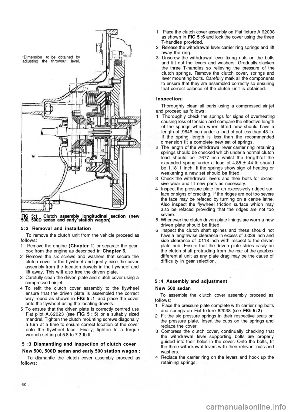
*Dimension to be obtained by
adjusting the throwout lever.
FIG 5:1 Clutch assembly longitudinal section (new
500, 500D sedan and early station wagon)
5 : 2 Removal and installation
To remove the clutch unit from the vehicle proceed as
follows:
1 Remove the engine (Chapter 1) or separate the gear-
box from the engine as described in Chapter 6.
2 Remove the six screws and washers that secure the
clutch cover to the flywheel and gently ease the cover
assembly from the location dowels in the flywheel and
lift away. This will also free the driven plate.
3 Carefully clean the driven plate and clutch cover using a
compressed air jet.
4 To refit the clutch cover assembly to the flywheel
ensure that the driven plate is assembled the correct
way round as shown in FIG 5 :1 and place the cover
onto the flywheel using the locating dowels.
5 To ensure that the driven plate is correctly centred use
Fiat pilot A.62023 (see FIG 5 : 5) or a suitably sized
mandrel. Tighten the clutch mounting screws diagonally
a turn at a time to ensure correct location of the cover
onto the flywheel face. Finally, tighten to a torque
wrench setting of 5.8 to 7.2 Ib ft.
5 :3 Dismantling and inspection of clutch cover
New 500, 500D sedan and early 500 station wagon :
To dismantle the clutch cover assembly proceed as
follows:
60
To assemble the clutch cover assembly proceed as
follows:
1 Place the pressure plate complete with carrier ring bolts
and springs on Fiat fixture 62038 (see FIG 5 : 2).
2 Fit the six pressure springs in their respective seats on
the pressure plate. Insert the cups on the springs and
replace the cover.
3 Compress the clutch cover, continually checking that
the withdrawal lever supporting bolts are properly
guided into their holes in the cover. Onto the bolts, fit
the three withdrawal levers w i t h their relevant nuts and
washers.
4 Replace the carrier ring on the levers and hook up the
retaining springs. 5 :4 Assembly and adjustment
N e w 500 sedan1 Place the clutch cover assembly on Fiat fixture A.62038
as shown in FIG 5 :6 and lock the cover using the three
T-handles provided.
2 Release the w i thdrawal lever carrier ring springs and lift
away the ring.
3 Unscrew the withdrawal lever fixing nuts on the bolts
and lift out the levers and washers. Gradually slacken
the three T-handles so relieving the pressure of the
clutch springs. Remove the clutch cover, springs and
lever mounting bolts. Carefully mark all the components
to ensure that they are assembled correctly so ensuring
that correct balance of the clutch unit is obtained.
Inspection:
Thoroughly clean all parts using a compressed air jet
and proceed as follows:
1 Thoroughly check the springs for signs of overheating
causing loss of tension and compare the effective length
of the springs which when fitted new should have a
length of .9646 inch under a load of not less than 43 Ib.
If the spring length is less t h a n t h e recommended
dimension fit a complete new set of springs.
2 The length of the withdrawal lever carrier ring retaining
springs should be checked which under a normal clutch
load should be .7677 inch whilst the length'of the
expanded spring under a load of 4.85 ± .44 Ib should
be 1.1811 inch. If the springs show sign of heating or
weakening a new set should be fitted.
3 Check the withdrawa l levers and their bolts for exces-
sive wear and fit new parts as necessary.
4 Inspect the pressure plate for an excessively ridged sur-
face or signs of cracking. If the ridges are not too severe
the face may be refaced by turning on a centre lathe.
Also inspect the flywheel friction surface which may
also be refaced providing that the ridges are not too
severe.
5 Whenever the clutch driven plate linings are worn a new
driven plate should be fitted.
6 Inspect the clutch shaft splines and these should not
have a lengthwise clearance in excess of .0039 inch and
side clearance of .0118 inch w i t h respect to the driven
plate hub. Ensure that the driven plate slides easily on
the clutch shaft protruding from the rear of the gearbox
differential unit as any plate drag may be the cause of
d i f f i c u l t y in gear selection.
Page 58 of 128
CHAPTER 6
GEARBOX AND DIFFERENTIAL UNIT
6:1
6:2
6:3
6:4
6:5
6:6Description
Removal of gearbox/differential unit
Dismantling — gearbox
Reassembly — gearbox
Dismantling — differential and final drive
Reassembly— differential and final drive6:7
6:8
6:9
6:10
6:11
6:12Final drive gear set adjustment
Replacement of gearbox/differential unit
Swing axle shafts and slip joints
Gear shift control mechanism
Modifications
Fault diagnosis
6 :1 Description
The gearbox and differential unit are housed in an
aluminium alloy casing made up of t w o parts which split
at the differential centre line. The output drive is trans-
mitted by means of t w o half axle drive shafts coupled
through wheel shafts and slip joints to the rear wheels (see
FIG 6 : 1)
The gearbox provides four forward-speeds and a reverse,
the fourth-speed being considered as an overdrive. All
gears except first and reverse gears, which are straight
toothed sliding gears, are in constant mesh and have heli-
cal teeth. No synchromesh is provided, gear engagement
being completed by sliding shifter sleeves of the dog
clutch type. The first-speed gear slides on the outside of
the third and fourth shifter sleeve, whilst the reverse gear
train moves on a fixed shaft. The clutch shaft is integral
with the third, top and combined and first and second gear
pinions, whilst the second gear pinion is splined at the
front end. An internal splined
coupling sleeve joins the
clutch shaft and the input shaft and transmits the power
from the engine to the gearbox. The mainshaft and
differential drive pinion are combined together and besides
carrying the constant mesh gears and the sliding first gear
pinion, it also has attached the sliding sleeves and hubs.
F50065 The speedometer drive pinion is located at the front end.
The gearbox/differential casing is attached to the engine
by six studs which locate in the crankcase. The front of the
unit rests upon the rubber mounted support which is
secured to the body floor.
The complete unit comprises three detachable parts
made up as follows:
1 The support for the connection of the gearbox to the
engine which also acts as part of the differential front
end and clutch/flywheel housing at rear.
2 A central body which is divided into two compartments.
The front compartment contains first, third, fourth and
reverse gears w i t h the primary shaft, layshaft and reverse
shaft as well as the necessary gear selection striker rods
and forks. The rear of this compartment also forms a half
cover for the differential unit.
3 The gearbox casing cover, which contains the second-
speed gears together with the relative fork, gear
selection rod and speedometer drive gears.
The central part of the casing is provided with a top
inspection cover. The primary shaft is coupled to the clutch
shaft through an internally splined sleeve and t w o pins
which are retained by rings. The primary shaft together
with the first, third and fourth driving gears form a cluster.