spare wheel FIAT 500 1973 1.G Workshop Manual
[x] Cancel search | Manufacturer: FIAT, Model Year: 1973, Model line: 500, Model: FIAT 500 1973 1.GPages: 128, PDF Size: 9.01 MB
Page 17 of 128

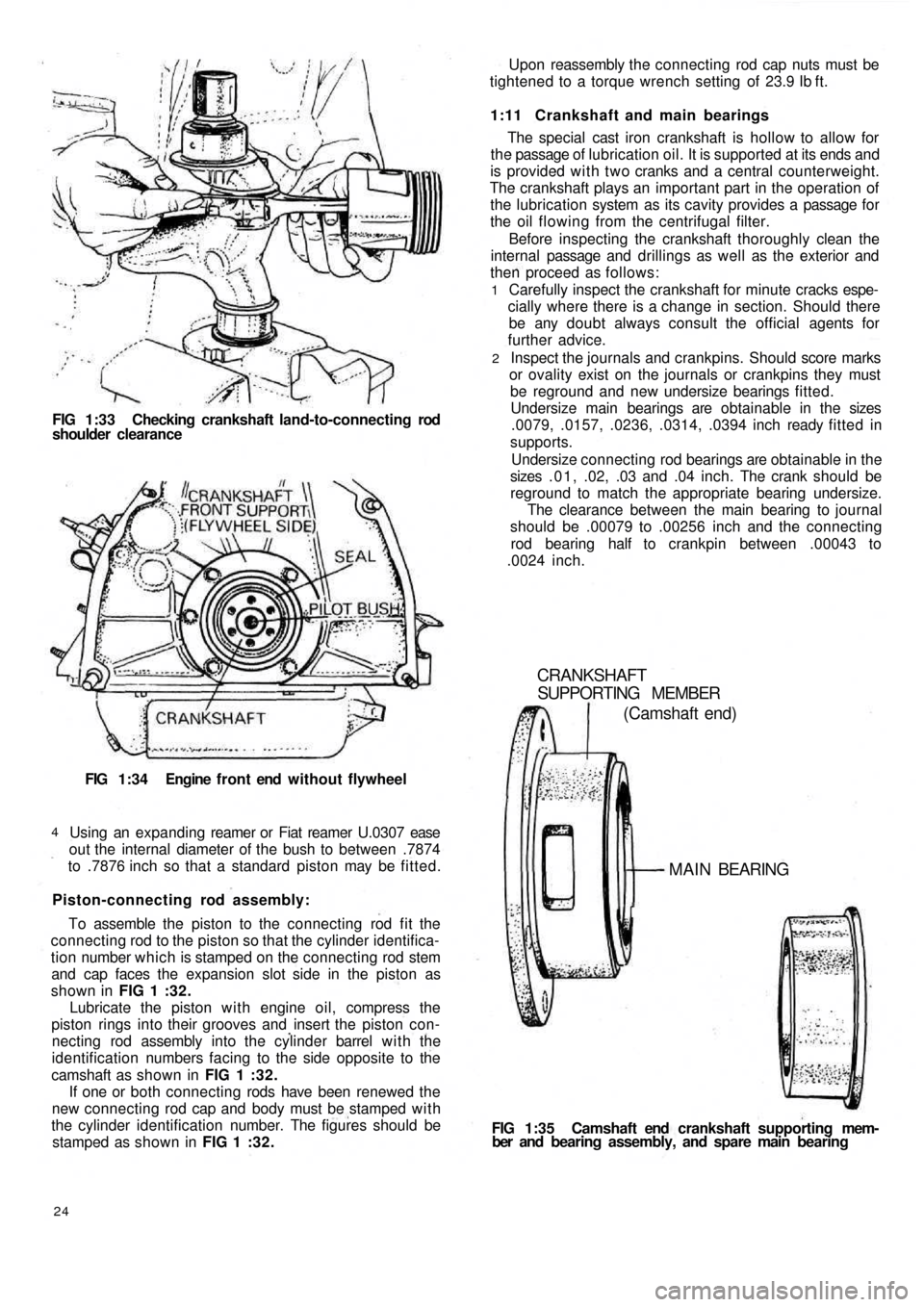
FIG 1:33 Checking crankshaft land-to-connecting rod
shoulder clearance
FIG 1:34 Engine f r o n t end without flywheel
Using an expanding reamer or Fiat reamer U.0307 ease
out the internal diameter of the bush to between .7874
to .7876 inch so that a standard piston may be fitted.
4
Piston-connecting rod assembly:
To assemble the piston to the connecting rod fit the
connecting rod to the piston so that the cylinder identifica-
tion number which is stamped on the connecting rod stem
and cap faces the expansion slot side in the piston as
shown in FIG 1 :32.
Lubricate the piston with engine oil, compress the
piston rings into their grooves and insert the piston con-
necting rod assembly into the cylinder barrel w i t h the
identification numbers facing to the side opposite to the
camshaft as shown in FIG 1 :32.
If one or both connecting rods have been renewed the
new connecting rod cap and body must be stamped w i t h
the cylinder identification number. The figures should be
stamped as shown in FIG 1 :32.
24
FIG 1:35 Camshaft end crankshaft supporting mem-
ber and bearing assembly, and spare main bearing
CRANKSHAFT
SUPPORTING MEMBER
(Camshaft end)
MAIN BEARING
Carefully inspect the crankshaft for minute cracks espe-
cially where there is a change in section. Should there
be any doubt always consult the official agents for
further advice.
Inspect the journals and crankpins. Should score marks
or ovality exist on the journals or crankpins they must
be reground and new undersize bearings fitted.
Undersize main bearings are obtainable in the sizes
.0079, .0157, .0236, .0314, .0394 inch ready fitted in
supports.
Undersize connecting rod bearings are obtainable in the
sizes .01, .02, .03 and .04 inch. The crank should be
reground to match the appropriate bearing undersize.
The clearance between the main bearing to journal
should be .00079 to .00256 inch and the connecting
rod bearing half to crankpin between .00043 to
.0024 inch.
2 1
The special cast iron crankshaft is hollow to allow for
the passage of lubrication oil. It is supported at its ends and
is provided with two cranks and a central counterweight.
The crankshaft plays an important part in the operation of
the lubrication system as its cavity provides a passage for
the oil flowing from the centrifugal filter.
Before inspecting the crankshaft thoroughly clean the
internal passage and drillings as well as the exterior and
then proceed as follows: 1:11 Crankshaft and main bearings Upon reassembly the connecting rod cap nuts must be
tightened to a torque wrench setting of 23.9 Ib ft.
Page 38 of 128

Air cleaner—station wagon:
A pleated paper air cleaner element is housed in a
special air intake chamber connected to the front of the
engine air cooling cowling (see FIG 4 : 2) . This chamber
will be seen located towards the rear of t h e power unit
compartment. Remove the retaining wing nut, lift off the
lid and the element can be withdrawn by lifting upwards.
2:10 Blow-by-gases recirculation device
Engine 110 F.000
All the oil vapours and blow-by-gases that are formed
in the engine crankcase are drawn to the cylinder head
cover recess 1 (see FIG 2:18). From here they travel into
the pipe 5 via a breather valve 2 which is firmly attached to
the oil filler cap 3 and the strainer 4 located in the filler
neck. The oil vapours and gases are then d r a w n back into
the duct 9 from the pipe 5 which connects the air cleaner
6 to the carburetter 7. This ensures a complete closed cir-
cuit circulation.
Engine 120.000:
From engine No. 288156 the oil vapours and blow-by-
gases instead of being exhausted to the atmosphere are
conveyed to the air cleaner and from here they are drawn
back into the combustion chambers. To ensure that an
excessive of oil vapour does not pass along the piping
with the blow-by-gases a diaphragm is fitted in the duct
in front of the breather valve 2 (see FIG 2 :18), the dia-
phragm comprising a filter gauze 11 and moveable parti-
tion 10.
It should be noted that the oil vapour strainer 4 (see
FIG 2:18) and the flame trap 8 can easily be removed
from their seating for cleaning or renewal.
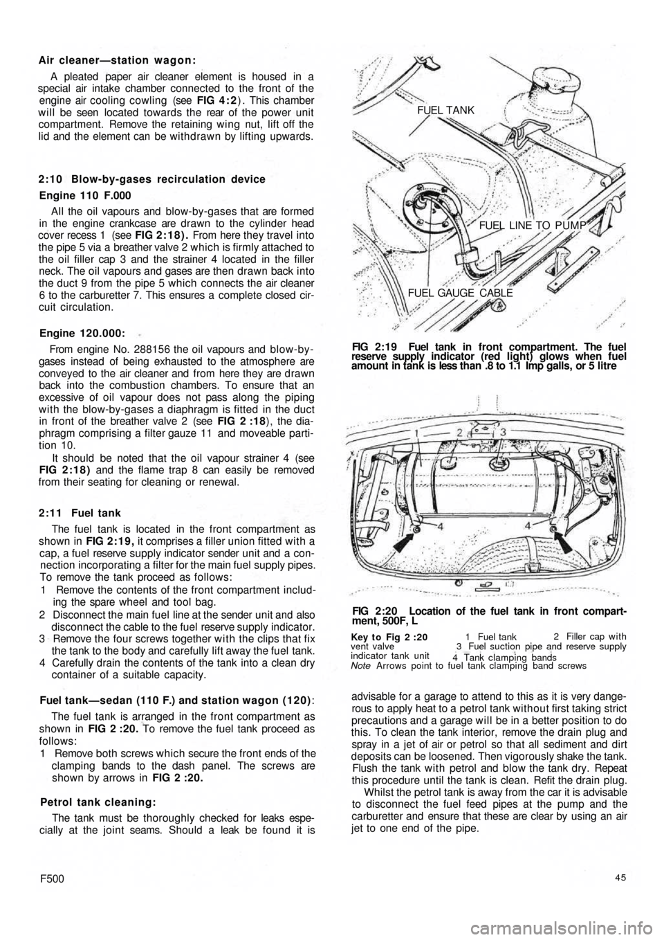
2 : 1 1 Fuel tank
The fuel tank is located in the front compartment as
shown in FIG 2:19, it comprises a filler union fitted with a
cap, a fuel reserve supply indicator sender unit and a con-
nection incorporating a filter for the main fuel supply pipes.
To remove the tank proceed as follows:
1 Remove the contents of the front compartment includ-
ing the spare wheel and tool bag.
2 Disconnect the main fuel line at the sender unit and also
disconnect the cable to the fuel reserve supply indicator.
3 Remove the four screws together w i t h the clips that fix
the tank to the body and carefully lift away the fuel tank.
4 Carefully drain the contents of the tank into a clean dry
container of a suitable capacity.
Fuel tank—sedan (110 F.) and station wagon (120):
The fuel tank is arranged in the front compartment as
shown in FIG 2 :20. To remove the fuel tank proceed as
follows:
1 Remove both screws which secure the front ends of the
clamping bands to the dash panel. The screws are
shown by arrows in FIG 2 :20.
Petrol tank cleaning:
The tank must be thoroughly checked for leaks espe-
cially at the joint seams. Should a leak be found it is
F50045
advisable for a garage to attend to this as it is very dange-
rous to apply heat to a petrol tank without first taking strict
precautions and a garage will be in a better position to do
this. To clean the tank interior, remove the drain plug and
spray in a jet of air or petrol so that all sediment and dirt
deposits can be loosened. Then vigorously shake the tank.
Flush the tank w i t h petrol and blow the tank dry. Repeat
this procedure until the tank is clean. Refit the drain plug.
Whilst the petrol tank is away from the car it is advisable
to disconnect the fuel feed pipes at the pump and the
carburetter and ensure that these are clear by using an air
jet to one end of the pipe.
Key t o Fig 2 :20
Note Arrows point to fuel tank clamping band screws vent valve
indicator tank unit1 Fuel tank2 Filler cap with
3 Fuel suction pipe and reserve supply
4 Tank clamping bands
FIG 2:20 Location of the fuel tank in front compart-
ment, 500F, L FIG 2:19 Fuel tank in front compartment. The fuel
reserve supply indicator (red light) glows when fuel
amount in tank is less than .8 to 1.1 Imp galls, or 5 litre FUEL TANK
FUEL LINE TO PUMP
FUEL GAUGE CABLE
Page 64 of 128

of wear, distorting or unevenness of the surfaces as this
part is very heavily pressed when the vehicle is negotia-
ting a corner. If the clearance to the idle pinions exceeds
.0059 inch the shaft must be renewed.
2 Inspect the ring gear and pinion seat, the side gears.and
the idle pinions for correct meshing. This will be shown
up by white marks on the sides of the gear teeth. Check
that none of the teeth are broken, chipped or exces-
sively worn and if any part is suspect then it must be
renewed not forgetting that the ring gear and pinion
come as a matched pair.
3 Inspect the condition of the ball and roller bearings, the
rollers and balls and working faces must not show signs
of pitting wear or cracking and if any part is suspect then
the race must be renewed.
4 Check that there is not any undue wear on the faces of
the thrust rings. Any slight indentations may be evened
out using a fine oil stone but if the damage is excessive
then new rings or oversize rings must befitted as neces-
sary. Thrust rings are supplied as service spares in the
following thicknesses.
Standard .0394 inch
Oversize .0512-.0591 inch
6:6 Reassembly—differential unit
To reassemble the differential case proceed as follows:
1 Press onto the differential half housing which carries
the ring gear one differential bearing inner race ensuring
that it is pushed fully home onto its seating. Install the
thrust ring and side gear (see FIG 6 : 7).
2 From t h e inside of the case insert the axle shaft com-
plete with pivot and runners that form the slip joint.
Also install the idle pinions and carrier shaft. Position
the ring gear onto the housing half and install the
differential pinion shaft retainer ring.
3 Press the other differential bearing inner race onto its
seating on the left differential housing half and replace
the left axle shaft complete with slip joint.
4 J o i n the t w o case halves together and tighten the
retaining screws and also the retaining screws of the
ring gear to a torque wrench setting of 23.1 Ib ft. Secure
all screws by bending up the lockplates.
5 Press t h e differential bearing outer races into their
seatings in the bearing housings and also f i t the o i l seals.
Also install the bearing housings over the driving shafts
together with the adjuster rings.
6 Install the differential unit assembly into the final drive
housing front half and bolt the rear
half onto it. Tighten
the six mounting nuts to a torque wrench setting of
27.5 Ib ft. Finally place the bearing housings in their
seats and tighten the mounting nuts to a torque wrench
setting of 13 lb ft.
It should be noted that after the gearbox has been over-
hauled the complete differential unit should only be in-
stalled after the drive pinion depth adjustments has been
carried out.
6 : 7 Final drive gear set adjustment
The installation and adjustment of the final drive gear
set requires special care otherwise the unit may have to be
dismantled again for further adjustment. So as to establish
the correct mesh of the t w o gears, their relative position is
accurately set during initial assembly at the factory.
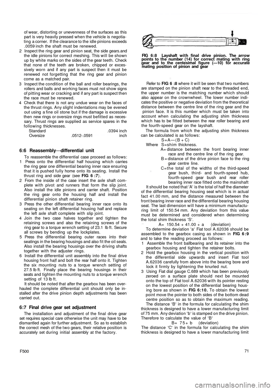
F50071 Refer to FIG 6 :8 where it will be seen that t w o numbers
are stamped on the pinion shaft near to the threaded end,
the upper number is the matching number which should
also appear on the crownwheel. The lower number indi-
cates the positive or negative deviation from the theoretical
distance between the centre line of the ring gear and the
pinion face. It is this number which must be taken into
account when calculating the adjusting shim thickness
which has to be fitted between the rear roller bearing and
the fourth-speed gear on the layshaft.
The formula from which the adjusting shim thickness
can be calculated is as follows:
S=A—(B + C)
Where S=shim thickness.
A= distance between the front bearing inner
race and the centre line of the ring gear.
B = distance of the drive pinion face to the ring
gear centre line.
C = t h e total of the widths of the third-speed
gear bush, third- and fourth-speed hub,
fourth-speed gear bush and rear roller
bearing inner race fitted onto the mainshaft
It should be noted that 'A' is the total of half the diameter
of the differential bearing housing seat which is in actual
fact 41.00 mm, and the distance measured between the
front bearing inner race and the differential bearing housing
seat. The last
dimension will have a minimum manufactu-
ring limit of 150.54 mm. Any deviation from this value
must be determined and considered when determining
the total shim thickness 'S'.
A= 150.54 + 41.00 + a (deviation)
To determine deviation 'a' Fiat tool A.62036 should be
assembled to the gearbox casing as shown in FIG 6 : 9
and to take the reading proceed as follows:
1 Assemble the front ballbearing and its retainer into the
gearbox housing and tighten the retainer bolts.
2 Hold the gearbox housing in the vertical position with
the differential side upwards and insert Fiat tool
A.62036 carefully from above into the bearing bore and
lock it firmly by tightening the knurled nut.
3 Using Fiat dial gauge C.689 which has been previously
zeroed on a surface plate should next be mounted
onto the t o p of Fiat tool A.62036 with its pointer resting
on the lowest position of the differential bearing hous-
ing bore as shown in FIG 6:10. To obtain the lowest
point move the pointer to both sides of the bottom dead
centre position so as to obtain the maximum reading.
The distance ' B ' in the formula for calculating the shim
thickness is designed to have a lower manufacturing limit
of 75 mm. Any deviation ' b ' is stamped on the drive pinion.
Therefore to calculate the value of ' B '
B = 7 5 + b (deviation)
The distance 'C' in the formula for calculating the shim
thickness is designed to have a lower manufacturing limit
FIG 6 : 8 Layshaft w i t h final drive pinion. The arrow
points to the number (14) for correct mating with ring
gear and to the centesimal figure (—10) for accurate
mating position of pinion and gear