FIAT 500 2019 Owner handbook (in English)
Manufacturer: FIAT, Model Year: 2019, Model line: 500, Model: FIAT 500 2019Pages: 228, PDF Size: 6.01 MB
Page 121 of 228
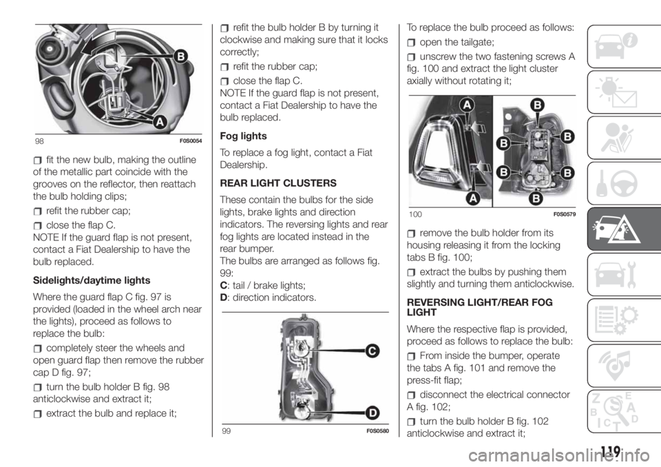
fit the new bulb, making the outline
of the metallic part coincide with the
grooves on the reflector, then reattach
the bulb holding clips;
refit the rubber cap;
close the flap C.
NOTE If the guard flap is not present,
contact a Fiat Dealership to have the
bulb replaced.
Sidelights/daytime lights
Where the guard flap C fig. 97 is
provided (loaded in the wheel arch near
the lights), proceed as follows to
replace the bulb:
completely steer the wheels and
open guard flap then remove the rubber
cap D fig. 97;
turn the bulb holder B fig. 98
anticlockwise and extract it;
extract the bulb and replace it;
refit the bulb holder B by turning it
clockwise and making sure that it locks
correctly;
refit the rubber cap;
close the flap C.
NOTE If the guard flap is not present,
contact a Fiat Dealership to have the
bulb replaced.
Fog lights
To replace a fog light, contact a Fiat
Dealership.
REAR LIGHT CLUSTERS
These contain the bulbs for the side
lights, brake lights and direction
indicators. The reversing lights and rear
fog lights are located instead in the
rear bumper.
The bulbs are arranged as follows fig.
99:
C: tail / brake lights;
D: direction indicators.To replace the bulb proceed as follows:
open the tailgate;
unscrew the two fastening screws A
fig. 100 and extract the light cluster
axially without rotating it;
remove the bulb holder from its
housing releasing it from the locking
tabs B fig. 100;
extract the bulbs by pushing them
slightly and turning them anticlockwise.
REVERSING LIGHT/REAR FOG
LIGHT
Where the respective flap is provided,
proceed as follows to replace the bulb:
From inside the bumper, operate
the tabs A fig. 101 and remove the
press-fit flap;
disconnect the electrical connector
A fig. 102;
turn the bulb holder B fig. 102
anticlockwise and extract it;
98F0S0054
99F0S0580
100F0S0579
119
Page 122 of 228
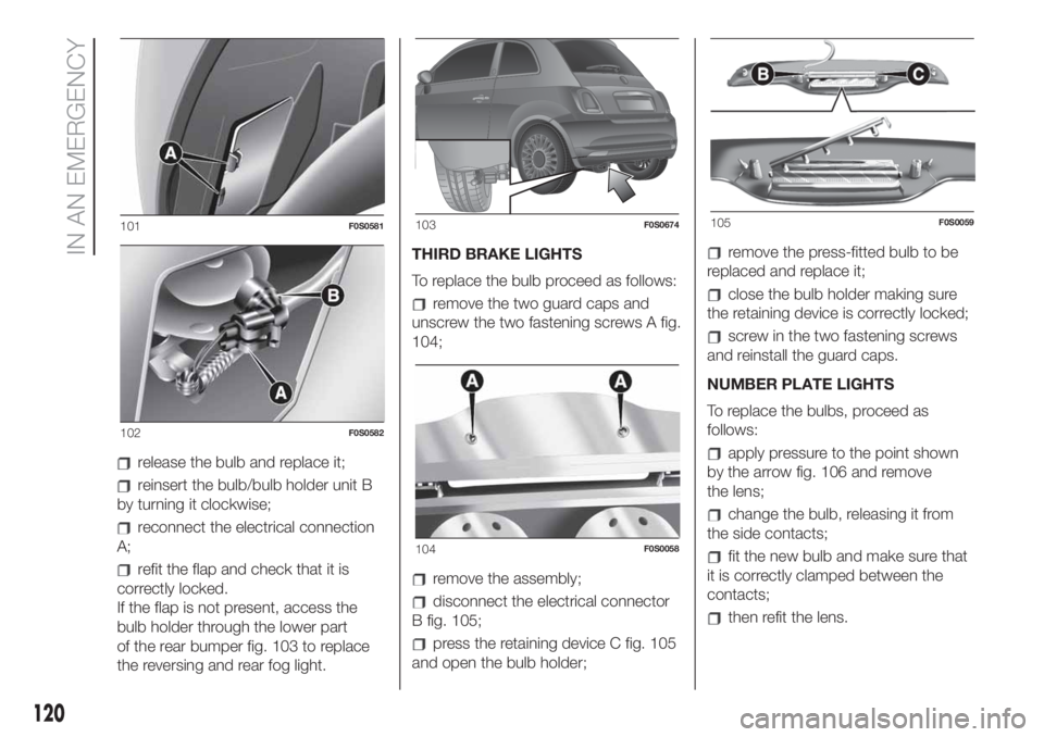
release the bulb and replace it;
reinsert the bulb/bulb holder unit B
by turning it clockwise;
reconnect the electrical connection
A;
refit the flap and check that it is
correctly locked.
If the flap is not present, access the
bulb holder through the lower part
of the rear bumper fig. 103 to replace
the reversing and rear fog light.THIRD BRAKE LIGHTS
To replace the bulb proceed as follows:
remove the two guard caps and
unscrew the two fastening screws A fig.
104;
remove the assembly;
disconnect the electrical connector
B fig. 105;
press the retaining device C fig. 105
and open the bulb holder;
remove the press-fitted bulb to be
replaced and replace it;
close the bulb holder making sure
the retaining device is correctly locked;
screw in the two fastening screws
and reinstall the guard caps.
NUMBER PLATE LIGHTS
To replace the bulbs, proceed as
follows:
apply pressure to the point shown
by the arrow fig. 106 and remove
the lens;
change the bulb, releasing it from
the side contacts;
fit the new bulb and make sure that
it is correctly clamped between the
contacts;
then refit the lens.
101F0S0581
102F0S0582
103F0S0674
104F0S0058
105F0S0059
120
IN AN EMERGENCY
Page 123 of 228
WARNING
143)Modifications or repairs to the electric
system that are not carried out properly
or do not take the system technical
specifications into account can cause
malfunctions leading to the risk of fire.
144)Halogen bulbs contain pressurised
gas, in the case of breakage they may
burst causing glass fragments to be
projected outwards.
145)Only replace the light bulbs when the
engine is off and in a position that does
not interfere with traffic and lets you safely
replace them (see the description in the
“Replacement” paragraph). Also ensure
that the engine is cold, to prevent the risk
of burns.
146)Before replacing the bulb, wait for the
exhaust ducts to cool down: DANGER
OF SCALDING!147)Due to the high power supply voltage,
gas discharge bulbs (Xenon) should only
be replaced by specialised personnel:
danger of death! Contact a Fiat Dealership.
WARNING
49)Halogen bulbs must be handled
holding the metallic part only. Touching the
transparent part of the bulb with your
fingers may reduce the intensity of the
emitted light and even reduce the lifespan
of the bulb. In the event of accidental
contact, wipe the bulb with a cloth
moistened with alcohol and let the bulb
dry.
50)Where possible, it is advisable to have
bulbs changed at a Fiat Dealership. The
correct operation and direction of the
external lights are absolutely essential for
the safety of the car and of compliance
with the law.
51)The intervention must be carried out
taking all precautions necessary to avoid
damaging the bodywork (please use a
sufficiently rigid and appropriately thick
plastic card).
REPLACING FUSES
148) 149) 150) 151) 152) 153)
DASHBOARD FUSE BOX
To access the fuses you must remove
the press-fitted cover A fig. 107.
The 5 A fuse B for door mirror
demisting is located in the diagnosis
socket area, as shown in fig. 108.
106F0S0139
107F0S0066
108F0S0677
121
Page 124 of 228

The dashboard fuse box shown is
located in the lower area next to the
pedal board.
ENGINE COMPARTMENT
JUNCTION BOX
52)
The fusebox is located on the right side
of the engine compartment. To access
the fuses, proceed as follows:
Fully press screw A fig. 109;
at the same time slowly rotate the
screw anticlockwise, until resistance is
encountered (do not overtighten);
slowly release the screw;
opening is indicated by the entire
screw head coming out of its seat;
remove cover B, sliding it upwards
on the side guides, as indicated in
the figure.Once the fuse has been replaced,
proceed as follows:
correctly refit the cover B in the side
guides of the casing;
slide it down completely from the
top;
fully tighten screw A using the
screwdriver provided;
at the same time slowly rotate the
screw clockwise, until resistance is
encountered (do not overtighten);
slowly release the screw;
closure is indicated by the securing
of the entire screw head in its housing.
The number identifying the electrical
component corresponding to each fuse
is shown on the control unit cover.
LPG versions
The LPG system components are
protected by specific fuses. Contact a
Fiat Dealership for replacement.
109F0S0606
122
IN AN EMERGENCY
Page 125 of 228
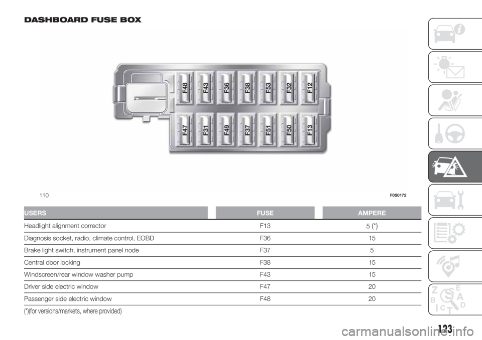
DASHBOARD FUSE BOX
USERSFUSE AMPERE
Headlight alignment corrector F13
5(*)
Diagnosis socket, radio, climate control, EOBD F36 15
Brake light switch, instrument panel node F37 5
Central door locking F38 15
Windscreen/rear window washer pump F43 15
Driver side electric window F47 20
Passenger side electric window F48 20
(*)(for versions/markets, where provided)
110F0S0172
123
Page 126 of 228
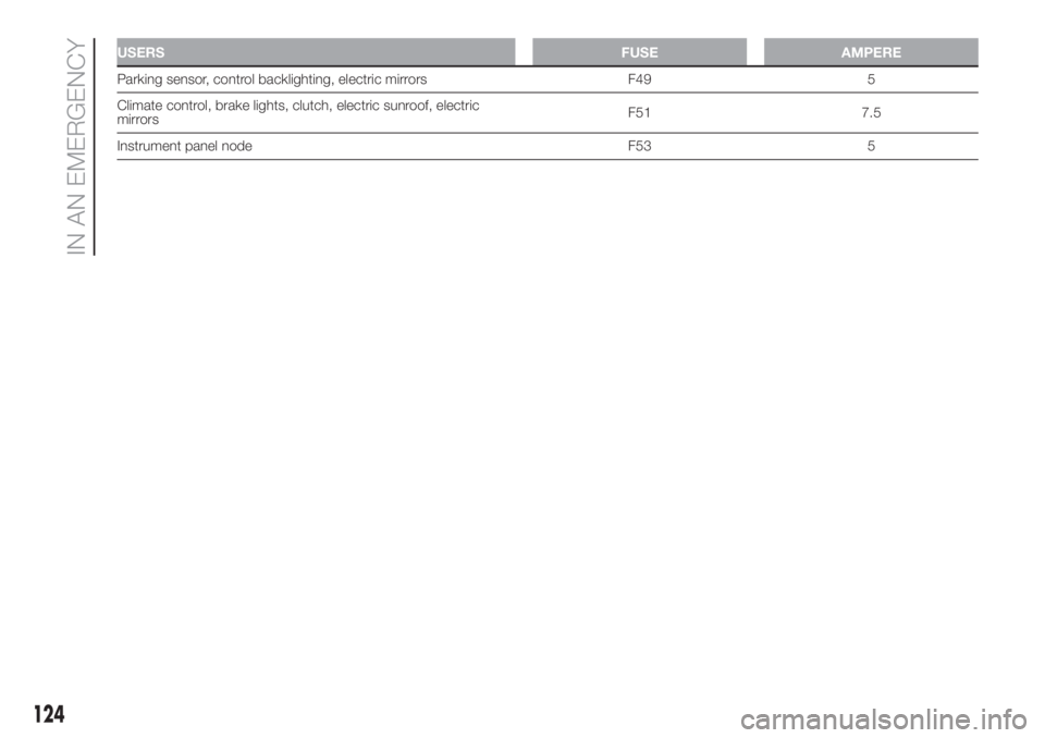
USERSFUSE AMPERE
Parking sensor, control backlighting, electric mirrors F49 5
Climate control, brake lights, clutch, electric sunroof, electric
mirrorsF51 7.5
Instrument panel node F53 5
124
IN AN EMERGENCY
Page 127 of 228
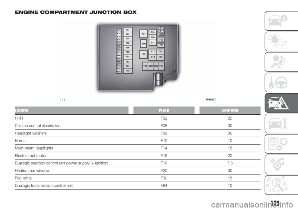
ENGINE COMPARTMENT JUNCTION BOX
USERSFUSE AMPERE
HI-FIF02 20
Climate control electric fan F08 30
Headlight washers F09 30
HornsF10 10
Main-beam headlights F14 15
Electric roof motor F15 20
Dualogic gearbox control unit power supply (+ ignition) F16 7.5
Heated rear window F20 30
Fog lightsF30 15
Dualogic transmission control unit F84 10
111F0S0607
125
Page 128 of 228
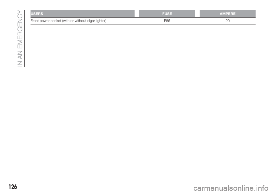
USERSFUSE AMPERE
Front power socket (with or without cigar lighter) F85 20
126
IN AN EMERGENCY
Page 129 of 228
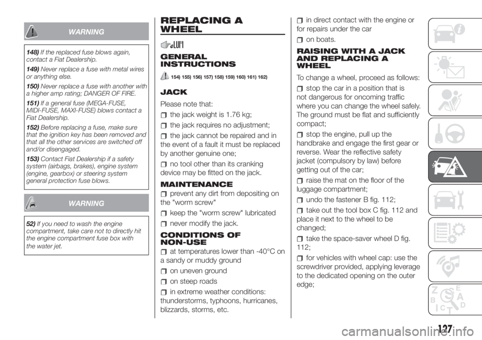
WARNING
148)If the replaced fuse blows again,
contact a Fiat Dealership.
149)Never replace a fuse with metal wires
or anything else.
150)Never replace a fuse with another with
a higher amp rating; DANGER OF FIRE.
151)If a general fuse (MEGA-FUSE,
MIDI-FUSE, MAXI-FUSE) blows contact a
Fiat Dealership.
152)Before replacing a fuse, make sure
that the ignition key has been removed and
that all the other services are switched off
and/or disengaged.
153)Contact Fiat Dealership if a safety
system (airbags, brakes), engine system
(engine, gearbox) or steering system
general protection fuse blows.
WARNING
52)If you need to wash the engine
compartment, take care not to directly hit
the engine compartment fuse box with
the water jet.
REPLACING A
WHEEL
GENERAL
INSTRUCTIONS
154) 155) 156) 157) 158) 159) 160) 161) 162)
JACK
Please note that:
the jack weight is 1.76 kg;
the jack requires no adjustment;
the jack cannot be repaired and in
the event of a fault it must be replaced
by another genuine one;
no tool other than its cranking
device may be fitted on the jack.
MAINTENANCE
prevent any dirt from depositing on
the "worm screw"
keep the "worm screw" lubricated
never modify the jack.
CONDITIONS OF
NON-USE
at temperatures lower than -40°C on
a sandy or muddy ground
on uneven ground
on steep roads
in extreme weather conditions:
thunderstorms, typhoons, hurricanes,
blizzards, storms, etc.
in direct contact with the engine or
for repairs under the car
on boats.
RAISING WITH A JACK
AND REPLACING A
WHEEL
To change a wheel, proceed as follows:
stop the car in a position that is
not dangerous for oncoming traffic
where you can change the wheel safely.
The ground must be flat and sufficiently
compact;
stop the engine, pull up the
handbrake and engage the first gear or
reverse. Wear the reflective safety
jacket (compulsory by law) before
getting out of the car;
raise the mat on the floor of the
luggage compartment;
undo the fastener B fig. 112;
take out the tool box C fig. 112 and
place it next to the wheel to be
changed;
take the space-saver wheel D fig.
112;
for vehicles with wheel cap: use the
screwdriver provided, applying leverage
to the dedicated opening on the outer
edge;
127
Page 130 of 228
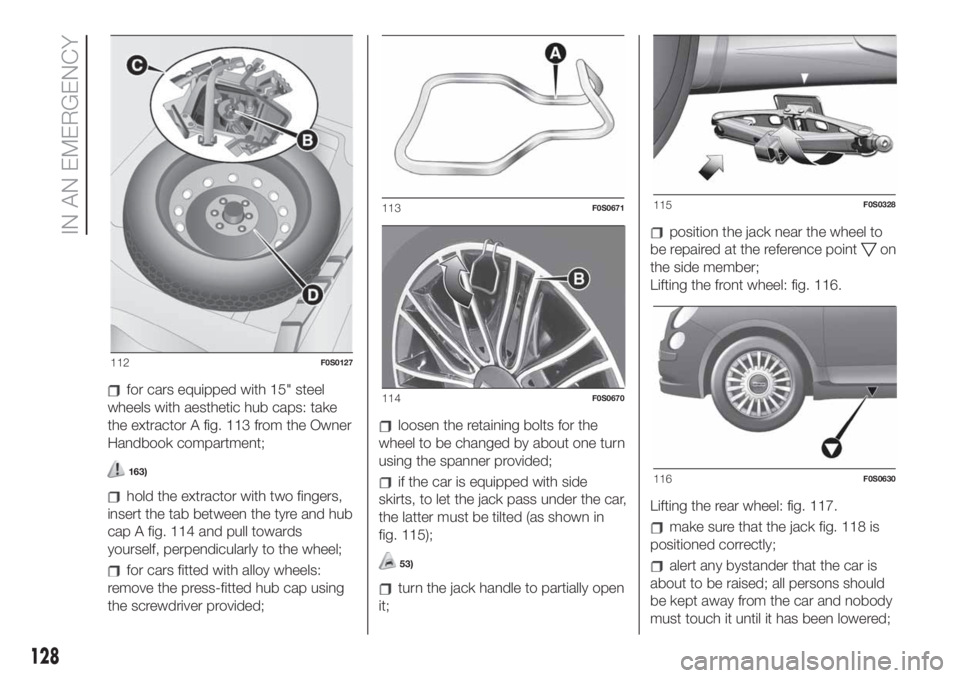
for cars equipped with 15" steel
wheels with aesthetic hub caps: take
the extractor A fig. 113 from the Owner
Handbook compartment;
163)
hold the extractor with two fingers,
insert the tab between the tyre and hub
cap A fig. 114 and pull towards
yourself, perpendicularly to the wheel;
for cars fitted with alloy wheels:
remove the press-fitted hub cap using
the screwdriver provided;
loosen the retaining bolts for the
wheel to be changed by about one turn
using the spanner provided;
if the car is equipped with side
skirts, to let the jack pass under the car,
the latter must be tilted (as shown in
fig. 115);
53)
turn the jack handle to partially open
it;
position the jack near the wheel to
be repaired at the reference point
on
the side member;
Lifting the front wheel: fig. 116.
Lifting the rear wheel: fig. 117.
make sure that the jack fig. 118 is
positioned correctly;
alert any bystander that the car is
about to be raised; all persons should
be kept away from the car and nobody
must touch it until it has been lowered;
112F0S0127
113F0S0671
114F0S0670
115F0S0328
116F0S0630
128
IN AN EMERGENCY