Eco FIAT 500 2020 Owner handbook (in English)
[x] Cancel search | Manufacturer: FIAT, Model Year: 2020, Model line: 500, Model: FIAT 500 2020Pages: 228, PDF Size: 6.01 MB
Page 102 of 228
DUALOGIC
TRANSMISSION
(for versions/markets, where provided)
42) 44)
OPERATING MODE
MANUAL MODE
In this mode, the driver decides when
to shift gear;
Proceed as follows:
press the brake pedal;
start the engine;
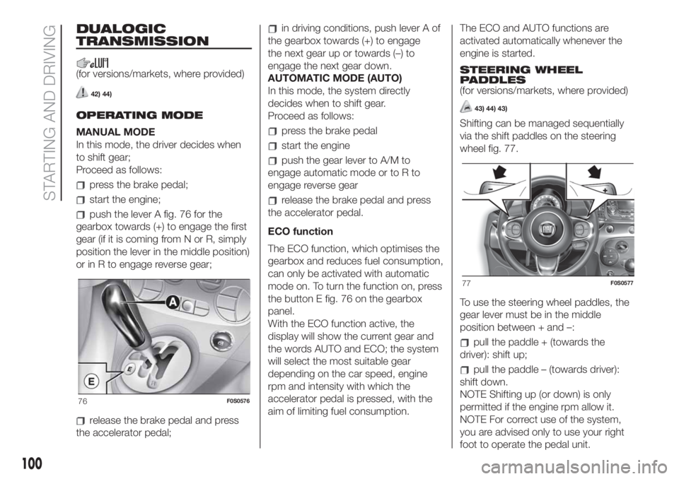
push the lever A fig. 76 for the
gearbox towards (+) to engage the first
gear (if it is coming from N or R, simply
position the lever in the middle position)
or in R to engage reverse gear;
release the brake pedal and press
the accelerator pedal;
in driving conditions, push lever A of
the gearbox towards (+) to engage
the next gear up or towards (–) to
engage the next gear down.
AUTOMATIC MODE (AUTO)
In this mode, the system directly
decides when to shift gear.
Proceed as follows:
press the brake pedal
start the engine
push the gear lever to A/M to
engage automatic mode or to R to
engage reverse gear
release the brake pedal and press
the accelerator pedal.
ECO function
The ECO function, which optimises the
gearbox and reduces fuel consumption,
can only be activated with automatic
mode on. To turn the function on, press
the button E fig. 76 on the gearbox
panel.
With the ECO function active, the
display will show the current gear and
the words AUTO and ECO; the system
will select the most suitable gear
depending on the car speed, engine
rpm and intensity with which the
accelerator pedal is pressed, with the
aim of limiting fuel consumption.The ECO and AUTO functions are
activated automatically whenever the
engine is started.
STEERING WHEEL
PADDLES
(for versions/markets, where provided)
43) 44) 43)
Shifting can be managed sequentially
via the shift paddles on the steering
wheel fig. 77.
To use the steering wheel paddles, the
gear lever must be in the middle
position between + and –:
pull the paddle + (towards the
driver): shift up;
pull the paddle – (towards driver):
shift down.
NOTE Shifting up (or down) is only
permitted if the engine rpm allow it.
NOTE For correct use of the system,
you are advised only to use your right
foot to operate the pedal unit.
76F0S0576
77F0S0577
100
STARTING AND DRIVING
Page 103 of 228
WARNING
42)Avoid keeping your hand placed on this
lever in between gear changes or
Auto/Manual mode.
43)Using the paddles incorrectly (paddles
pushed towards the dashboard) could
break them.
44)If the transmission is faulty, contact a
Fiat Dealership as soon as possible to have
the system checked.
45)Using the paddles incorrectly (paddles
pushed towards the dashboard) could
break them.
DUALDRIVE
ELECTRIC POWER
STEERING
(for versions/markets, where provided)
Turning on/off (CITY function)
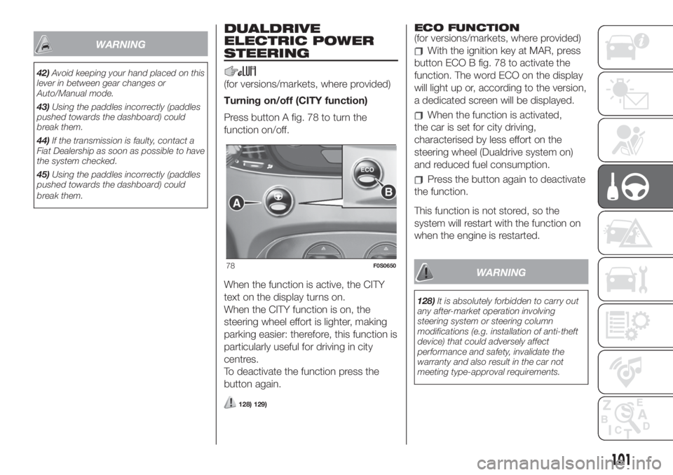
Press button A fig. 78 to turn the
function on/off.
When the function is active, the CITY
text on the display turns on.
When the CITY function is on, the
steering wheel effort is lighter, making
parking easier: therefore, this function is
particularly useful for driving in city
centres.
To deactivate the function press the
button again.
128) 129)
ECO FUNCTION
(for versions/markets, where provided)
With the ignition key at MAR, press
button ECO B fig. 78 to activate the
function. The word ECO on the display
will light up or, according to the version,
a dedicated screen will be displayed.
When the function is activated,
the car is set for city driving,
characterised by less effort on the
steering wheel (Dualdrive system on)
and reduced fuel consumption.
Press the button again to deactivate
the function.
This function is not stored, so the
system will restart with the function on
when the engine is restarted.
WARNING
128)It is absolutely forbidden to carry out
any after-market operation involving
steering system or steering column
modifications (e.g. installation of anti-theft
device) that could adversely affect
performance and safety, invalidate the
warranty and also result in the car not
meeting type-approval requirements.
78F0S0650
101
Page 105 of 228
WARNING
130)If the battery needs to be replaced,
always contact a Fiat Dealership. Replace
the battery with one of the same type
(HEAVY DUTY) and with the same
specifications.
131)Before opening the bonnet, make
sure that the vehicle is switched off and the
key is in the STOP position. Please follow
the instructions on the decal near the front
crossmember. It is advisable to extract
the key when there are other people in the
car. The car should always be left after
the key has been removed or turned to the
STOP position. When refuelling, make
sure that the car is switched off with the
key in the STOP position.132)We recommend that you remove the
key from the ignition if other people remain
in the vehicle. Exit from the vehicle only
after having removed the ignition key
or having rotated it to the STOP position.
During refuelling, make sure that the engine
is off and that the ignition key is in the
STOP position.
133)For cars with Dualogic transmission, if
the engine is automatically stopped on a
slope, the engine should be restarted
by moving the gear lever to + or – without
releasing the brake pedal. For cars with
Dualogic transmission, where the Hill
Holder function is present, in the case of
car stopped on a slope, the engine does
not cut off automatically, so as to make the
Hill Holder function - which is active only
when the engine is running - available.
WARNING
46)If the climate comfort is to be favoured,
the Start&Stop system can be deactivated,
for a continuous operation of the climate
control system.
SPEED LIMITER
(for versions/markets, where provided)
ACTIVATING THE DEVICE
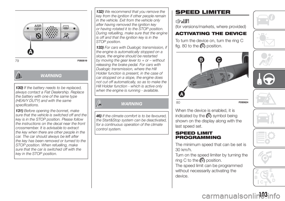
To turn the device on, turn the ring C
fig. 80 to the
position.
When the device is enabled, it is
indicated by the
symbol being
shown on the display along with the
last speed set.
SPEED LIMIT
PROGRAMMING
The minimum speed that can be set is
30 km/h.
Turn on the speed limiter by turning the
ring C to the
position.
The speed limit can be programmed
without necessarily activating the
device.
79F0S0519
80F0S0624
103
Page 106 of 228
To store a speed value higher than
that displayed
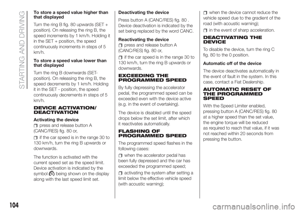
Turn the ring B fig. 80 upwards (SET +
position). On releasing the ring B, the
speed increments by 1 km/h. Holding it
in the SET + position, the speed
continuously increments in steps of 5
km/h.
To store a speed value lower than
that displayed
Turn the ring B downwards (SET-
position). On releasing the ring B, the
speed decrements by 1 km/h. Holding
it in the SET - position, the speed
continuously decrements in steps of 5
km/h.
DEVICE ACTIVATION/
DEACTIVATION
Activating the device
press and release button A
(CANC/RES) fig. 80 or,
if the car speed is in the range 30 to
130 km/h, turn the ring B upwards or
downwards.
The function is activated with the
current speed set as the speed limit.
Device activation is indicated by the
symbol
being shown on the display
along with the last speed limit set.Deactivating the device
Press button A (CANC/RES) fig. 80 .
Device deactivation is indicated by the
set being replaced by the word CANC.
Reactivating the device
press and release button A
(CANC/RES) fig. 80 or,
if the car speed is in the range 30 to
130 km/h, turn the ring B upwards or
downwards.
EXCEEDING THE
PROGRAMMED SPEED
By fully depressing the accelerator
pedal, the programmed speed can be
exceeded even with the device active
(e.g. in the event of overtaking).
The device is disabled until the speed
drops below the set limit, after which
it reactivates automatically.
FLASHING OF
PROGRAMMED SPEED
The programmed speed flashes in the
following cases:
when the accelerator pedal has
been fully depressed and the car has
exceeded the programmed speed;
activating the system after setting a
limit below the effective vehicle speed
(with acoustic warning);
when the device cannot reduce the
vehicle speed due to the gradient of the
road (with acoustic warning);
in the event of sharp acceleration.
DEACTIVATING THE
DEVICE
To disable the device, turn the ring C
fig. 80 to the 0 position.
Automatic off of the device
The device deactivates automatically in
the event of fault in the system. In this
case, contact a Fiat Dealership.
AUTOMATIC RESET OF
THE PROGRAMMED
SPEED
With the Speed Limiter enabled,
pressing button A (CANC/RES) fig. 80
at a higher speed than the set value,
the engine torque will be reduced
as required to reach that value, if it was
not reached within 20 seconds from
pressing the button.
104
STARTING AND DRIVING
Page 108 of 228
WARNING
134)When travelling with the device active,
never move the gear lever to neutral.
135)In case of a malfunction or failure of
the device, contact a Fiat Dealership.
136)The electronic Cruise Control can be
dangerous if the system cannot keep a
constant speed. In specific conditions
speed may be excessive, resulting in the
risk of losing control of the vehicle and
causing accidents. Do not use the device
in heavy traffic or on winding, icy, snowy or
slippery roads.
PARKING SENSORS
(for versions/markets, where provided)
137)
47) 48)
SENSORS
Parking sensors are located in the rear
bumper fig. 82 and detect and inform
the driver, through an intermittent
acoustic signal, of the presence of
obstacles at the rear of the car.
ACOUSTIC SIGNAL
When reverse gear is engaged and
there is an obstacle behind the car an
acoustic warning is activated and
the warning varies as the distance of
the obstacle from the bumper varies.The frequency of the acoustic signal:
increases as the distance between
car and obstacle decreases
becomes continuous when the
distance between the car and
the obstacle is less than 30 cm and
stops immediately if the distance
increases
is constant if the distance between
the vehicle and the obstacle is
unchanged. If this situation concerns
the side sensors, the signal will stop
after approximately 3 seconds to avoid,
for example, indications in the event
of manoeuvres along a wall.
If several obstacles are detected by the
sensors, only the nearest one is
considered.
INDICATIONS ON
DISPLAY
(versions with colour display)
When the sensors are activated, the
screen shown in fig. 83 appears on the
display.
The system indicates a detected
obstacle by displaying an arc according
to the distance of the obstacle and its
position in relation to the car.
When the system detects an obstacle,
an arc appears in one or more positions
according to the distance of the
obstacle from the car.
82F0S0578
106
STARTING AND DRIVING
Page 109 of 228
If an object is detected in the rear left,
central or right zone, the display shows
a flashing arc in the corresponding
zone and a sound is emitted.
As the car approaches the object, the
display shows one or more flashing
arcs that approach the car, and the
sound becomes more frequent until it
becomes continuous.
The colour on the display depends on
the distance from and position of the
obstacle. The car is close to the
obstacle when a blinking red
arc appears on the display (to the right,
in the centre or to the left) and a
continuous sound is emitted. If there
are several obstacles, the closest one is
indicated.FAULT INDICATIONS
Parking sensor faults will be indicated
when reverse is engaged by warning
light
or by the icon(versions
with colour display) on the instrument
panel and by the relevant message
in the display (for versions/markets,
where provided).
OPERATION WITH A
TRAILER
The operation of the sensors is
automatically deactivated when the
trailer electric cable plug is inserted in
the tow hook socket of the car. The
sensors are automatically reactivated
when the trailer's cable plug is
removed.
WARNING
137)Parking and other dangerous
manoeuvres are, however, always the
driver’s responsibility. While carrying out
these manoeuvres, always make sure that
no people (especially children) or animals
are in the area concerned. The parking
sensors are used to assist the driver, who
must never allow his attention to lapse
during potentially dangerous manoeuvres,
even those executed at low speeds.
WARNING
47)For correct operation of the system,
sensors must always be clean from mud,
dirt, snow or ice. Be careful not to scratch
or damage the sensors while cleaning
them. Avoid using dry, rough or hard
cloths. The sensors must be washed using
clean water, with the addition of vehicle
shampoo if necessary. When using special
washing equipment such as high pressure
jets or steam cleaning, clean the sensors
very quickly keeping the jet more than
10 cm away.
48)Have interventions on the bumper in
the area of the sensors carried out only by
a Fiat Dealership. Interventions on the
bumper that are not carried out properly
may compromise the operation of the
parking sensors.
83F0S0558
107
Page 113 of 228
IMPORTANT Only use the adapter
supplied with the vehicle as it is
equipped with a dedicated fuel
pre-filter.
Fuel - Vehicle
compatibility
identification Graphic
symbol for consumer
information in
accordance with
EN16942
The symbols shown below facilitated
recognising the correct fuel type to
be used on your car.
Before proceeding with refuelling,
check the symbols inside the fuel filler
flap (where provided) and compare
them with the symbols shown on the
fuel pump (where provided).
Symbols for petrol powered carsE5: Unleaded petrol containing up to
2.7% (m/m) oxygen and with maximum
5.0% (V/V) ethanol compliant with
EN228.
E10: Unleaded petrol containing up to
3.7% (m/m) oxygen and with maximum
10.0% (V/V) ethanol compliant with
EN228.
Symbols for petrol/LPG bi-fuel cars
E5: Unleaded petrol containing up to
2.7% (m/m) oxygen and with maximum
5.0% (V/V) ethanol compliant with
EN228.
E10: Unleaded petrol containing up to
3.7% (m/m) oxygen and with maximum
10.0% (V/V) ethanol compliant with
EN228.
LPG: Automotive LPG compliant with
EN589.
WARNING
138)Do not bring naked flames or lit
cigarettes near to the fuel tank opening:
fire risk. Keep your face away from the fuel
filler to prevent breathing in harmful
vapours.
139)Do not use a mobile phone near the
refuelling pump: risk of fire.
140)During normal service the catalyst
reaches high temperatures; therefore do
not park the car over inflammable materials
(grass, dry leaves, pine needles, etc.): fire
hazard.
87F0S0666
88F0S0667
111
Page 115 of 228
IN AN EMERGENCY
A punctured tyre or a burnt-out bulb?
At times, a problem may interfere
with our journey.
The pages on emergencies can help
you to deal with critical situations
independently and with calm.
In an emergency we recommend that
you call the freephone number found in
the Warranty Booklet.
It is also possible to call the national or
international universal freephone
number to search for the nearest
Dealership.HAZARD WARNING LIGHTS...........114
CHANGING A BULB .......................114
REPLACING FUSES........................121
REPLACING A WHEEL ...................127
FIX&GO KIT .....................................131
JUMP STARTING ............................134
FUEL CUT-OFF SYSTEM ................135
TOWING THE VEHICLE ..................136
113
Page 120 of 228
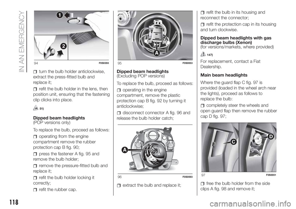
turn the bulb holder anticlockwise,
extract the press-fitted bulb and
replace it;
refit the bulb holder in the lens, then
position unit, ensuring that the fastening
clip clicks into place.
51)
Dipped beam headlights
(POP versions only)
To replace the bulb, proceed as follows:
operating from the engine
compartment remove the rubber
protection cap B fig. 90;
press the fastener A fig. 95 and
remove the bulb holder;
remove the pressure-fitted bulb and
replace it;
refit the bulb holder locking it
correctly;
refit the rubber cap.Dipped beam headlights
(Excluding POP versions)
To replace the bulb, proceed as follows:
operating in the engine
compartment, remove the plastic
protection cap B fig. 92 by turning it
anticlockwise;
disconnect connector A fig. 96 and
release the bulb holder catch;
extract the bulb and replace it;
refit the bulb in its housing and
reconnect the connector;
refit the protection cap in its housing
and turn clockwise.
Dipped beam headlights with gas
discharge bulbs (Xenon)
(for versions/markets, where provided)
147)
For replacement, contact a Fiat
Dealership.
Main beam headlights
Where the guard flap C fig. 97 is
provided (loaded in the wheel arch near
the lights), proceed as follows to
replace the bulb:
completely steer the wheels and
open guard flap then remove the rubber
cap D fig. 97;
free the bulb holder from the side
clips A fig. 98 and remove it;
94F0S035595F0S0053
96F0S059397F0S0051
118
IN AN EMERGENCY
Page 122 of 228
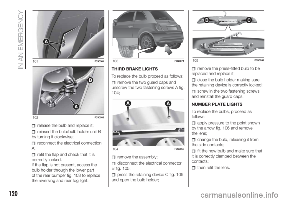
release the bulb and replace it;
reinsert the bulb/bulb holder unit B
by turning it clockwise;
reconnect the electrical connection
A;
refit the flap and check that it is
correctly locked.
If the flap is not present, access the
bulb holder through the lower part
of the rear bumper fig. 103 to replace
the reversing and rear fog light.THIRD BRAKE LIGHTS
To replace the bulb proceed as follows:
remove the two guard caps and
unscrew the two fastening screws A fig.
104;
remove the assembly;
disconnect the electrical connector
B fig. 105;
press the retaining device C fig. 105
and open the bulb holder;
remove the press-fitted bulb to be
replaced and replace it;
close the bulb holder making sure
the retaining device is correctly locked;
screw in the two fastening screws
and reinstall the guard caps.
NUMBER PLATE LIGHTS
To replace the bulbs, proceed as
follows:
apply pressure to the point shown
by the arrow fig. 106 and remove
the lens;
change the bulb, releasing it from
the side contacts;
fit the new bulb and make sure that
it is correctly clamped between the
contacts;
then refit the lens.
101F0S0581
102F0S0582
103F0S0674
104F0S0058
105F0S0059
120
IN AN EMERGENCY