light FIAT 500 ABARTH 2012 2.G Owner's Manual
[x] Cancel search | Manufacturer: FIAT, Model Year: 2012, Model line: 500 ABARTH, Model: FIAT 500 ABARTH 2012 2.GPages: 76, PDF Size: 2.95 MB
Page 43 of 76
• If the light remains lit with the engine running, your vehicle will usually be drivable;however, see an authorized service center immediately. If the light is flashing when
the engine is running, immediate service is required and you may experience
reduced performance, an elevated/rough idle or engine stall and your vehicle may
require towing.
- Electronic Stability Control (ESC) OFF Indicator Light
• This light indicates the Electronic Stability Control system (ESC) has been turned offby the driver.
- Electronic Stability Control (ESC) Activation / Malfunction Indicator
Light
• The “ESC Activation/Malfunction Indicator Light” in the instrument cluster will come on for four seconds when the ignition switch is turned to the ON/RUN position. If the
“ESC Activation/Malfunction Indicator Light” comes on continuously with the engine
running, a malfunction has been detected in the ESC system. If this light remains on,
see your authorized dealer as soon as possible to have the problem diagnosed and
corrected.
NOTE:
• The “ESC Off Indicator Light” and the “ESC Activation/Malfunction Indicator Light” come on momentarily each time the ignition switch is turned to ON/RUN.
• Each time the ignition is turned to ON/RUN, the ESC system will be ON even if it was turned off previously.
TTC (Tire Transfer Control)
• The TTC system uses the brakes to prevent unwanted wheelspin during corning, tomaximize acceleration and minimize understeer during aggressive driving. This
feature is active in all modes. While TTC is active, the “ESC” lamp in the instrument
cluster may flash
- Tire Pressure Monitoring System (TPMS) Light
• Each tire, should be checked monthly, when cold and inflated to the inflationpressure recommended by the vehicle manufacturer on the vehicle placard or tire
inflation pressure label. (If your vehicle has tires of a different size than the size
indicated on the vehicle placard or tire inflation pressure label, you should determine
the proper tire inflation pressure for those tires.)
• As an added safety feature, your vehicle has been equipped with a Tire Pressure Monitoring System (TPMS) that illuminates a low tire pressure telltale when one or
more of your tires is significantly under-inflated. Accordingly, when the low tire
pressure telltale illuminates, you should stop and check your tires as soon as
possible, and inflate them to the proper pressure. Driving on a significantly
under-inflated tire causes the tire to overheat and can lead to tire failure.
Under-inflation also reduces fuel efficiency and tire tread life, and may affect the
vehicle’s handling and stopping ability.
WHAT TO DO IN EMERGENCIES
41
Page 44 of 76
•IF THE LIGHT STARTS FLASHING INDICATING A LOW TIRE PRESSURE,
ADJUST THE AIR PRESSURE IN THE LOW TIRE TO THE AIR PRESSURE
SHOWN ON THE VEHICLE PLACARD OR TIRE INFLATION PRESSURE
LABEL LOCATED ON THE DRIVER'S DOOR. NOTE: AFTER INFLATION,
THE VEHICLE MAY NEED TO BE DRIVEN FOR 20 MINUTES BEFORE THE
FLASHING LIGHT WILL TURN OFF.
• Please note that the TPMS is not a substitute for proper tire maintenance, and it is the driver’s responsibility to maintain correct tire pressure, even if under-inflation has
not reached the level to trigger illumination of the TPMS low tire pressure telltale.
• Your vehicle has also been equipped with a TPMS malfunction indicator to indicate when the system is not operating properly. The TPMS malfunction indicator is
combined with the low tire pressure telltale. When the system detects a malfunction,
the telltale will flash for approximately one minute and then remain continuously
illuminated. This sequence will continue each time the vehicle is restarted as long as
the malfunction exists.
• When the malfunction indicator is illuminated, the system may not be able to detect or signal low tire pressure as intended. TPMS malfunctions may occur for a variety
of reasons, including the installation of replacement or alternate tires or wheels on
the vehicle that prevent the TPMS from functioning properly. Always check the
TPMS malfunction telltale after replacing one or more tires or wheels on your vehicle,
to ensure that the replacement or alternate tires and wheels allow the TPMS to
continue to function properly.
NOTE: Tire pressures change by approximately 1 psi (7 kPa) per 12° F (7° C) of air
temperature change. Keep this in mind when checking tire pressure inside a garage,
especially in the Winter. Example: If garage temperature is 68°F (20°C) and the outside
temperature is 32°F (0°C), then the cold tire inflation pressure should be increased by
3 psi (21 kPa), which equals 1 psi (7 kPa) for every 12°F (7°C) for this outside
temperature condition.
CAUTION!
The TPMS has been optimized for the original equipment tires and wheels. TPMS
pressures and warning have been established for the tire size equipped on your
vehicle. Undesirable system operation or sensor damage may result when using
replacement equipment that is not of the same size, type, and/or style.
Aftermarket wheels can cause sensor damage. Do not use tire sealant from a
can, or balance beads if your vehicle is equipped with a TPMS, as damage to the
sensors may result.
BRAKE- Brake Warning Light
• The Brake Warning light illuminates when there is either a system malfunction or the parking brake is applied. If the light is on and the parking brake is not applied, it
indicates a possible brake hydraulic malfunction, brake booster problem or an
Anti-Lock Brake System problem.
• Please have your vehicle serviced immediately.
WHAT TO DO IN EMERGENCIES
42
Page 45 of 76
WARNING!
Driving a vehicle with the red brake light on is dangerous. Part of the brake
system may have failed. It will take longer to stop the vehicle. You could have a
collision. Have the vehicle checked immediately.
- Malfunction Indicator Light (MIL)
• Certain conditions, such as a loose or missing gas cap, poor fuel quality, etc., mayilluminate the MIL after engine start. The vehicle should be serviced if the light stays
on through several typical driving cycles. In most situations, the vehicle will drive
normally and not require towing.
• If the MIL flashes when the engine is running, serious conditions may exist that could lead to immediate loss of power or severe catalytic converter damage. We
recommend you do not operate the vehicle. Have the vehicle serviced immediately.
- Charging System Light
• This light shows the status of the electrical charging system. If the charging systemlight remains on, it means that the vehicle is experiencing a problem with the
charging system.
• We recommend you do not continue driving if the charging system light is on. Have the vehicle serviced immediately.
- Oil Pressure Warning Light
• This light indicates low engine oil pressure. If the light turns on while driving, stop thevehicle and shut off the engine as soon as possible. A chime will sound for four
minutes when this light turns on.
• We recommend you do not operate the vehicle or engine damage will occur. Have the vehicle serviced immediately.
- Anti-Lock Brake (ABS) Light
• This light monitors the Anti-Lock Brake System (ABS).
• If the light is not on during starting, stays on, or turns on while driving, werecommend you drive to the nearest service center and have the vehicle serviced
immediately.
- Air Bag Warning Light
• If the light is not on during starting, stays on, or turns on while driving, have thevehicle serviced by an authorized service center immediately.
WHAT TO DO IN EMERGENCIES
43
Page 54 of 76
• Vehicle can be towed on a flatbed truck (all wheels off the ground).
NOTE: If it is necessary to use the accessories while being towed (wipers, defrosters,
etc.), the key must be in the ON/RUN position. Make certain the transmission remains in
NEUTRAL.
Without The Ignition Key
• Special care must be taken when the vehicle is towed with the ignition in the OFF/LOCK position. A dolly should be used under the front wheels if the rear wheels
are raised. Proper towing equipment is necessary to prevent damage to the vehicle.
CAUTION!
• Failure to follow these towing methods can cause severe transmissiondamage. Such damage is not covered by the New Vehicle Limited Warranty.
• If the vehicle being towed requires steering, the ignition switch must be in the ON/RUN position.
• Do not attempt to use sling-type equipment when towing. When securing the vehicle to a flatbed truck, do not attach to front or rear suspension
components. Damage to your vehicle may result from improper towing.
ENHANCED ACCIDENT RESPONSE SYSTEM
• In the event of an impact causing airbag deployment, if the communication networkremains intact, and the power remains intact, depending on the nature of the event
the ORC will determine whether to have the Enhanced Accident Response System
perform the following functions:
• Cut off fuel to the engine.
• Flash hazard lights as long as the battery has power or until the ignition key is turned off.
• Turn on the interior lights, which remain on as long as the battery has power or until the ignition key is removed.
• Unlock the doors automatically.
• After the event occurs, when the system is active, the message "Fuel Cutoff See Handbook" is displayed.
• Carefully check the vehicle for fuel leaks in the engine compartment and on the ground near the engine compartment and fuel tank before resetting the system and
starting the engine.
NOTE: In order to start the engine and move the vehicle to a safe location after an
impact, the System Reset Procedure must be completed.
System Reset Procedure
• After an impact causing airbag deployment, the left and right turn signal lights, located in the instrument panel cluster, will both be blinking, until the ignition is
turned off.
• In order to move your vehicle to the side of the road you must follow the system reset procedure.
WHAT TO DO IN EMERGENCIES
52
Page 55 of 76
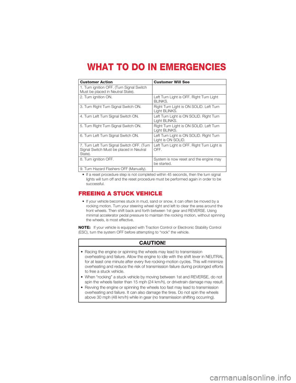
Customer ActionCustomer Will See
1. Turn ignition OFF. (Turn Signal Switch
Must be placed in Neutral State).
2. Turn ignition ON. Left Turn Light is OFF. Right Turn Light
BLINKS.
3. Turn Right Turn Signal Switch ON. Right Turn Light is ON SOLID. Left Turn Light BLINKS.
4. Turn Left Turn Signal Switch ON. Left Turn Light is ON SOLID. Right Turn Light BLINKS.
5. Turn Right Turn Signal Switch ON. Right Turn Light is ON SOLID. Left Turn Light BLINKS.
6. Turn Left Turn Signal Switch ON. Left Turn Light is ON SOLID. Right Turn Light is ON SOLID.
7. Turn Left Turn Signal Switch OFF. (Turn
Signal Switch Must be placed in Neutral
State). Left Turn Light is OFF. Right Turn Light is
OFF.
8. Turn ignition OFF. System is now reset and the engine may
be started.
9. Turn Hazard Flashers OFF (Manually).
• If a reset procedure step is not completed within 45 seconds, then the turn signal lights will turn off and the reset procedure must be performed again in order to be
successful.
FREEING A STUCK VEHICLE
• If your vehicle becomes stuck in mud, sand or snow, it can often be moved by arocking motion. Turn your steering wheel right and left to clear the area around the
front wheels. Then shift back and forth between 1st gear and REVERSE. Using
minimal accelerator pedal pressure to maintain the rocking motion, without spinning
the wheels, is most effective.
NOTE: If your vehicle is equipped with Traction Control or Electronic Stability Control
(ESC), turn the system OFF before attempting to “rock” the vehicle.
CAUTION!
• Racing the engine or spinning the wheels may lead to transmission overheating and failure. Allow the engine to idle with the shift lever in NEUTRAL
for at least one minute after every five rocking-motion cycles. This will minimize
overheating and reduce the risk of transmission failure during prolonged efforts
to free a stuck vehicle.
• When “rocking” a stuck vehicle by moving between 1st and REVERSE, do not spin the wheels faster than 15 mph (24 km/h), or drivetrain damage may result.
• Revving the engine or spinning the wheels too fast may lead to transmission overheating and failure. It can also damage the tires. Do not spin the wheels
above 30 mph (48 km/h) while in gear (no transmission shifting occurring).
WHAT TO DO IN EMERGENCIES
53
Page 62 of 76
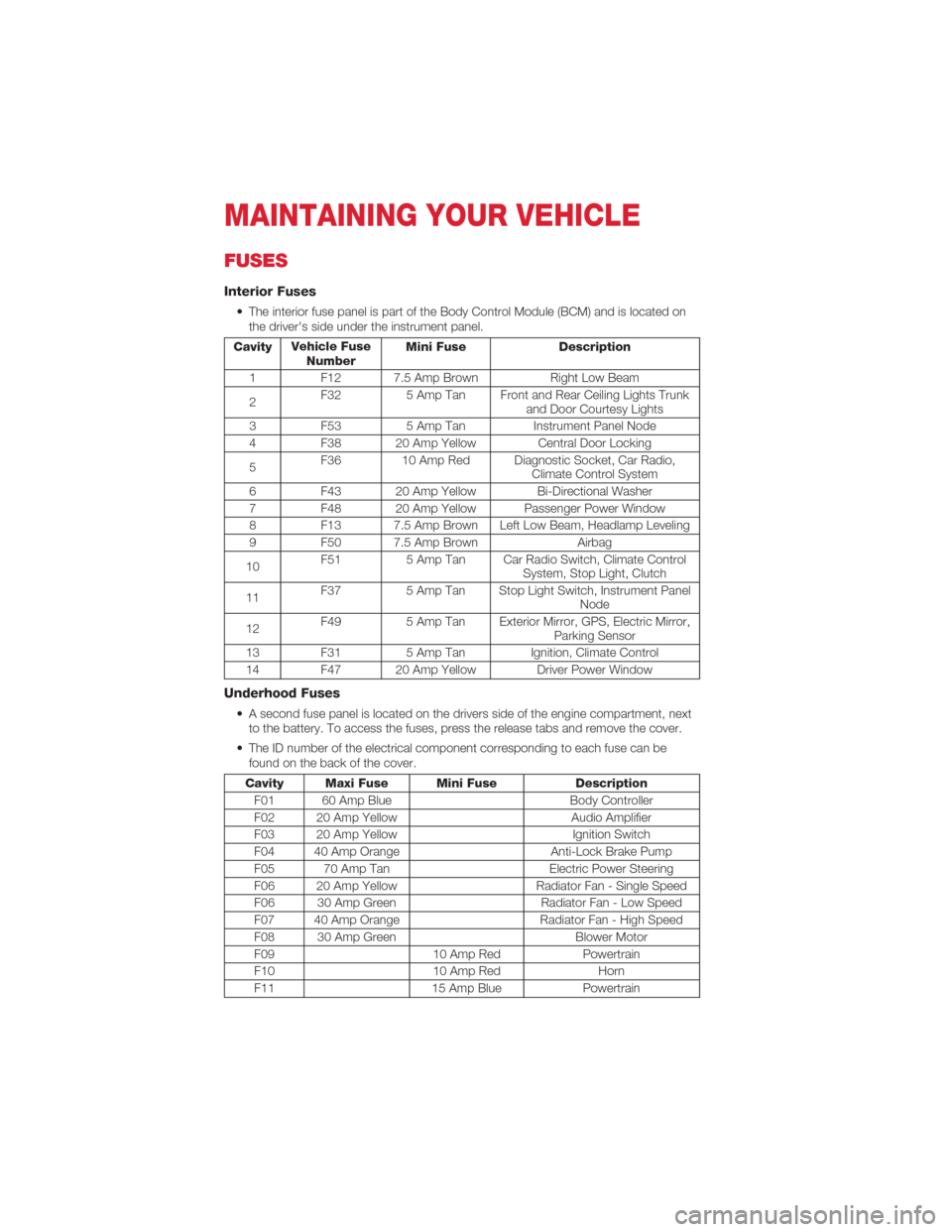
FUSES
Interior Fuses
• The interior fuse panel is part of the Body Control Module (BCM) and is located onthe driver's side under the instrument panel.
Cavity Vehicle Fuse
Number Mini Fuse Description
1 F12 7.5 Amp Brown Right Low Beam
2 F32
5 Amp Tan Front and Rear Ceiling Lights Trunk
and Door Courtesy Lights
3 F53 5 Amp Tan Instrument Panel Node
4 F38 20 Amp Yellow Central Door Locking
5 F36 10 Amp Red Diagnostic Socket, Car Radio,
Climate Control System
6 F43 20 Amp Yellow Bi-Directional Washer
7 F48 20 Amp Yellow Passenger Power Window
8 F13 7.5 Amp Brown Left Low Beam, Headlamp Leveling
9 F50 7.5 Amp Brown Airbag
10 F51
5 Amp Tan Car Radio Switch, Climate Control
System, Stop Light, Clutch
11 F37
5 Amp Tan Stop Light Switch, Instrument Panel
Node
12 F49
5 Amp Tan Exterior Mirror, GPS, Electric Mirror,
Parking Sensor
13 F31 5 Amp TanIgnition, Climate Control
14 F47 20 Amp Yellow Driver Power Window
Underhood Fuses
• A second fuse panel is located on the drivers side of the engine compartment, next to the battery. To access the fuses, press the release tabs and remove the cover.
• The ID number of the electrical component corresponding to each fuse can be found on the back of the cover.
Cavity Maxi Fuse Mini Fuse Description
F01 60 Amp Blue Body Controller
F02 20 Amp Yellow Audio Amplifier
F03 20 Amp Yellow Ignition Switch
F04 40 Amp Orange Anti-Lock Brake Pump
F05 70 Amp Tan Electric Power Steering
F06 20 Amp Yellow Radiator Fan - Single Speed
F06 30 Amp Green Radiator Fan - Low Speed
F07 40 Amp Orange Radiator Fan - High Speed
F08 30 Amp Green Blower Motor
F09 10 Amp RedPowertrain
F10 10 Amp RedHorn
F11 15 Amp BluePowertrain
MAINTAINING YOUR VEHICLE
60
Page 63 of 76
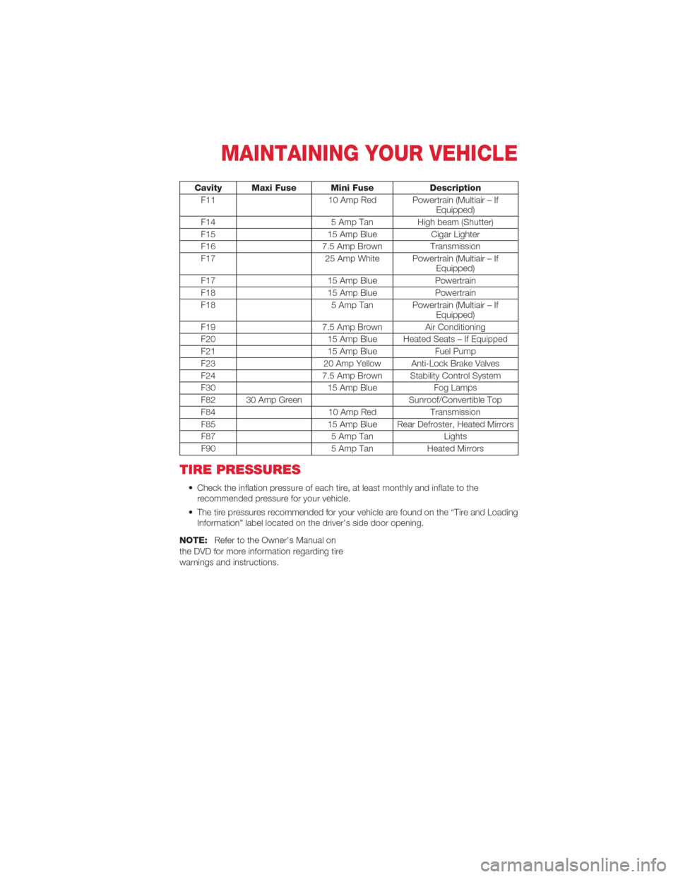
Cavity Maxi Fuse Mini FuseDescription
F11 10 Amp Red Powertrain (Multiair – If
Equipped)
F14 5 Amp Tan High beam (Shutter)
F15 15 Amp BlueCigar Lighter
F16 7.5 Amp BrownTransmission
F17 25 Amp White Powertrain (Multiair – If
Equipped)
F17 15 Amp BluePowertrain
F18 15 Amp BluePowertrain
F18 5 Amp Tan Powertrain (Multiair – If
Equipped)
F19 7.5 Amp Brown Air Conditioning
F20 15 Amp Blue Heated Seats – If Equipped
F21 15 Amp BlueFuel Pump
F23 20 Amp Yellow Anti-Lock Brake Valves
F24 7.5 Amp Brown Stability Control System
F30 15 Amp BlueFog Lamps
F82 30 Amp Green Sunroof/Convertible Top
F84 10 Amp RedTransmission
F85 15 Amp Blue Rear Defroster, Heated Mirrors
F87 5 Amp TanLights
F90 5 Amp TanHeated Mirrors
TIRE PRESSURES
• Check the inflation pressure of each tire, at least monthly and inflate to the
recommended pressure for your vehicle.
• The tire pressures recommended for your vehicle are found on the “Tire and Loading Information” label located on the driver’s side door opening.
NOTE: Refer to the Owner's Manual on
the DVD for more information regarding tire
warnings and instructions.
MAINTAINING YOUR VEHICLE
61
Page 65 of 76
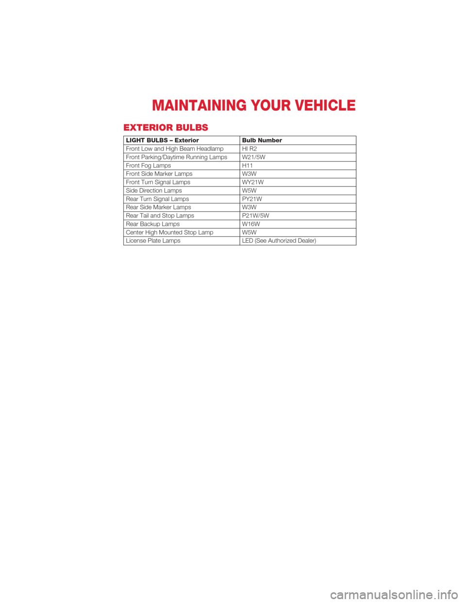
EXTERIOR BULBS
LIGHT BULBS – ExteriorBulb Number
Front Low and High Beam Headlamp HI R2
Front Parking/Daytime Running Lamps W21/5W
Front Fog Lamps H11
Front Side Marker Lamps W3W
Front Turn Signal Lamps WY21W
Side Direction Lamps W5W
Rear Turn Signal Lamps PY21W
Rear Side Marker Lamps W3W
Rear Tail and Stop Lamps P21W/5W
Rear Backup Lamps W16W
Center High Mounted Stop Lamp W5W
License Plate Lamps LED (See Authorized Dealer)
MAINTAINING YOUR VEHICLE
63
Page 68 of 76
AUTHENTIC ACCESSORIES BY MOPAR®
• The following highlights just some of the many Authentic FIAT 500 AbarthAccessories by Mopar featuring a fit, finish, and functionality specifically for your FIAT
500 Abarth.
• In choosing Authentic Accessories you gain far more than expressive style, premium protection, or extreme entertainment, you also benefit from enhancing your vehicle
with accessories that have been thoroughly tested and factory-approved.
• For the full line of Authentic FIAT 500 Abarth Accessories by Mopar, visit your local FIAT dealership or online at mopar.com.
EXTERIOR:
• Chrome Hood Spear • Side Window Air Deflectors• Vehicle Cover
• Chrome Mirror Cover • Front End Cover • Locking Fuel Cap
• Chrome Fuel Door • Molded Splash Guards
INTERIOR:
• Door Sill Guards • Roadside Safety Kit • Slush Mats
• Chrome Shift Knob • Premium Carpet Floor Mats• Cargo Organizer
• Key Covers
ELECTRONICS:
• GPS Tracking System(s) • Rear Park Distance Sensors• Sound System Upgrades
• Portable Navigation Systems • Wi-Fi
• Interior/Ambient Lighting
CARRIERS:
• Roof Rack • Bike Carrier• Canoe Carrier
• Snowboard/Ski Carrier • Luggage Carrier • Hitch-mount Bike Carrier
MOPAR ACCESSORIES
66
Page 69 of 76
Air Conditioning.............20
Airbag ...................9
Airbag Light ...............43
Anti-Lock Brake System (ABS) ....43
Automatic Temperature
Control (ATC) ..............21
Automatic Transmission Fluid Type ...............57
Battery Charging System Light . . . ....43
Jump Starting ............50
Belts, Seat ................8
BLUE&ME™ Hands-Free
Communication .............30
Brake Fluid ...............57
Brake System Warning Light .............42
Break-In Recommendations,
New Vehicle ...............15
Bulb Replacement ...........63
Charging System Light . . . ......43
Check Engine Light (Malfunction
Indicator Light) .............43
Child Restraint ..............10
Child Restraint Tether Anchors ....10
Climate Control .............20
Clock Setting ..............29
Cooling System Coolant Capacity ...........57
Cruise Control (Speed Control) ....18
Cruise Light ...............18
Customer Assistance ..........64
Defects, Reporting ...........65
Defroster, Rear Window . . ......20
Defroster, Windshield ..........20
Electronic Speed Control
(Cruise Control) .............18
Electronic Throttle Control
Warning Light ..............40
Electronic Vehicle Information
Center (EVIC) ............ 35,36
Electronics Your Vehicle's Sound System ....26Emergency, In Case of
Jump Starting ............50
Towing . ...............51
Engine Break-In Recommendations ....15
Compartment . . . ..........56
Malfunction Indicator
(Check Engine) . . ..........43
Oil Selection . ............57
Overheating . . ............44
Enhanced Accident Response
Feature ..................52
Exterior Lights . .............63
Fluid Capacities . . . . . . . . .....57
Fluids . . . . . . . ............57
Folding Rear Seat ............13
Freeing A Stuck Vehicle . . . . . . . . 53
Fuel Specifications . . . ..........57
Hands-Free Communication -
BLUE&ME™ . . . . . . . . .......30
Headlights High
Beam . . . ...........16
Heated Mirrors ........... 20,21
High Beam/Low Beam Select
(Dimmer) Switch . . . .........16
Hood Release . . ............55
Instrument Cluster ............6
Indicators ................7
Instrument Cluster
Warning Lights . . . . . . . . . . . . 6,40
Intermittent Wipers (Delay Wipers) . . . 17
Introduction . ...............2
iPod
®Control ..............34
iPod®/USB/MP3 Control ........34
Jump Starting ..............50
KeyFob ..................8
Lane Change Assist . .........15
INDEX
67