instrument panel FIAT 500 ABARTH 2012 2.G User Guide
[x] Cancel search | Manufacturer: FIAT, Model Year: 2012, Model line: 500 ABARTH, Model: FIAT 500 ABARTH 2012 2.GPages: 76, PDF Size: 2.95 MB
Page 7 of 76
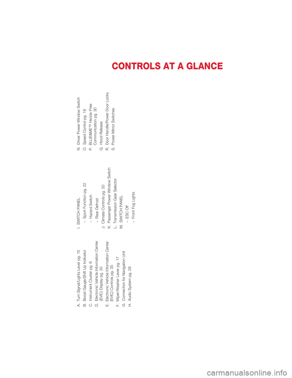
A. Turn Signal/Lights Lever pg. 15
B. Boost Gauge/Shift Up Indicator
C. Instrument Cluster pg. 6
D. Electronic Vehicle Information Center(EVIC) Display pg. 35
E. Electronic Vehicle Information Center (EVIC) Controls pg. 35
F. Wiper/Washer Lever pg. 17
G. Connection for Navigation Unit
H. Audio System pg. 28 I. SWITCH PANEL
−Sport Function pg. 22
− Hazard Switch
− Rear Defrost
J. Climate Controls pg. 20
K. Passenger Power Window Switch
L. Transmission Gear Selector
M. SWITCH PANEL −ESC Off
− Front Fog Lights N. Driver Power Window Switch
O. Speed Control pg. 18
P. BLUE&ME™ Hands-Free
Communication pg. 30
Q. Hood Release
R. Door Handle/Power Door Locks
S. Power Mirror Switches
CONTROLS AT A GLANCE
5
Page 12 of 76
WARNING!
• Relying on the air bags alone could lead to more severe injuries in a collision.The air bags work with your seat belt to restrain you properly. In some
collisions, the air bags won't deploy at all. Always wear your seat belts even
though you have air bags.
• Being too close to the steering wheel or instrument panel during Advanced Front Air Bag deployment could cause serious injury, including death. Air bags
need room to inflate. Sit back, comfortably extending your arms to reach the
steering wheel or instrument panel.
• Supplemental Side Air Bag Inflatable Curtains and Supplemental Seat-Mounted Side Air Bags need room to inflate. Do not lean against the
door or window. Sit upright in the center of the seat.
• Being too close to the Supplemental Side Air Bag Inflatable Curtain and/or Seat-Mounted Side Air Bag during deployment could cause you to be severely
injured or killed.
• Do not drive your vehicle after the air bags have deployed. If you are involved in another collision, the air bags will not be in place to protect you.
• After any collision, the vehicle should be taken to an authorized dealer immediately.
CHILD RESTRAINTS
• Children 12 years and under should ride properly buckled up in a rear seat, ifavailable. According to crash statistics, children are safer when properly restrained in
the rear seats rather than in the front.
• Every state in the United States and every Canadian province requires that small children ride in proper restraint systems. This is the law, and you can be prosecuted
for ignoring it.
Installing The LATCH - Compatible Child Restraint System
• Your vehicle's second row passenger seats are equipped with the child restraintanchorage system called LATCH, which stands for Lower Anchors and Tethers for
CHildren. LATCH child restraint anchorage systems are installed in both rear seating
positions.
• The LATCH lower anchorages are round bars, located at the rear of the seat cushion where it meets the seatback. They can be readily identified by the symbol
located on the seatback directly above the anchorages and are just visible when you
lean into the rear seat to install the child restraint.
• In addition, there are tether strap anchorages behind each rear seating position located on the back of the seat.
• NEVER use the same lower anchorage to attach more than one child restraint.
GETTING STARTED
10
Page 34 of 76
ButtonShort press function (less than
1 second) Long press
function (more than
1 second)
PHONE HANG UP Reject an incoming call and end a phone call in progress
End an active call and switch to a
call waiting (on hold) –
PRESET UP/OK (left
side back of steering
wheel) Confirm manually selected menu
option
Switch phone conversation from the
hands-free phone to your mobile
phone and vice versa
Select displayed message –
SCAN UP/SCAN
DOWN (left side back
of steering wheel Scroll BLUE&ME™ menu items
Scroll through media player tracks
Scroll inbox messages –
Steering Wheel Audio Controls • The right hand control on the rear of the steering wheel is a rocker type switch with a pushbutton in the center. Press the switch up for Volume +. Press the switch down
for Volume –. The button in the center is the SRC button used to change audio
sources (e.g. AM, FM, CD, Media Player).
• The left hand control on the rear of the steering wheel is also a rocker type switch with a pushbutton in the center. Press the top of the switch to Scan Up. Press the
bottom of the switch to Scan Down. The button in the center is the PRESET UP/OK
button.
BLUE&ME™ Hands-Free Communication
• To use the hands-free feature, you need a Bluetooth®wireless technology enabled
mobile phone. This hands-free feature gives you the possibility of interacting vocally
with your mobile phone while driving, even if your mobile device does not feature this
capability. You can also interact with your mobile phone manually and visually using
the steering wheel controls and the instrument panel EVIC display.
• To get started with BLUE&ME™ hands-free feature with voice recognition, you have to simply pair your Bluetooth
®wireless technology enabled mobile phone with the
system.
Pair Your Mobile Phone • Press the VR steering wheel button and say “Settings” then, at the end of the BLUE&ME™ message say “Pairing”.
• The system will show the phone pairing PIN number on the EVIC display. For the next two steps, consult your mobile phone owner’s manual about Bluetooth
®pairing
procedures for your phone.
• On your mobile phone, search for devices equipped with Bluetooth
®wireless
technology (the setting on your mobile phone might be called Discover or New
Device). In this list you will find BLUE&ME™ (name identifying the BLUE&ME™
system on your car): select it.
ELECTRONICS
32
Page 35 of 76
• When prompted by the mobile phone, enter the PIN number shown on theinstrument panel display using your mobile phone keypad. If pairing is successful,
the system will say “Connecting” and at the end the display will show as
confirmation message, the ID of the paired mobile phone.
• It is essential to wait until you see this confirmation message on the display. Pressing the PHONE/MAIN button on the steering wheel or the MUTE/ESC button before the
message is displayed may cancel the pairing process. If the pairing process fails, an
error message will be displayed: in this event repeat the pairing procedure.
• At first pairing, BLUE&ME™ will say “Welcome” immediately after connecting. This message will no longer be heard when your phone automatically connects to the
BLUE&ME™ system on future ignition cycles.
• BLUE&ME™ will ask if you would like to copy your paired phone phonebook to BLUE&ME™. It is recommended to copy it. To start copying the phonebook say
“Yes”, otherwise say “No”.
• For certain mobile phones the phonebook is not copied automatically, in this case you must transfer the phonebook contacts using your mobile phone keypad. If
BLUE&ME™ asks you to do this, then perform this procedure following the
instructions specific to your mobile phone and press the PHONE/MAIN button on
the steering wheel when you have finished.
Making a Phone Call • Assume that “John Smith” is one of the contacts stored in your phonebook.
• To call John Smith, proceed as follows:
• Press the steering wheel button PHONE/MAIN and pronounce “Call John Smith”.
• If the name is recognized, the system will display the recognized contact’s information on the display screen.
• If there is just one phone number for John Smith in your phonebook, the system will ask if you would like to call John Smith. To start the call say “Yes”, otherwise say
“No”.
• If John Smith has several phone numbers, the system will ask which phone number you would like to call (e.g.: “Call John Smith (at) Work or (at) Home?”). Answer with
the type of required phone number (e.g.: “(at) Home”).
• If John Smith has several phone numbers but the “location” (i.e.: the type of phone number like work, home, etc.) is missing, the system will display the selected
contact and a list of related phone numbers on the instrument cluster display. The
hands-free phone system will ask if you would like to call the phone number
displayed. To respond with “yes”, say “Yes”, otherwise say “No”. If this is the correct
contact but the wrong number, say “Forward” or “Backward” to navigate to the
phone number you’d like to call. To call the displayed phone number, pronounce
“Call”. You can also scroll through the phone number list manually by pressing the
buttons on the back of the steering wheel until you find the required number. Then,
press the PRESET UP/OK button on the rear of the steering wheel to start the call.
• To end the phone call, press the PHONE HANG UP button on the steering wheel.
• Refer to the BLUE&ME™ User's Manual on the DVD for more details.
ELECTRONICS
33
Page 49 of 76
If the sealant (white fluid) does not flowwithin0–10seconds through the Sealant
Hose (6):
1. Press the Power Button (4) to turn Off the TIREFIT kit. Disconnect the Sealant Hose (6) from the valve stem. Make sure the valve stem is free of debris. Reconnect the
Sealant Hose (6) to the valve stem. Check that the Mode Select Knob (5) is in the
Sealant Mode position and not Air Mode. Press the Power Button (4) to turn On the
TIREFIT kit.
2. Connect the Power Plug (8) to a different 12 Volt power outlet in your vehicle or another vehicle, if available. Make sure the engine is running before turning ON the
TIREFIT kit.
3. The Sealant Bottle (1) may be empty due to previous use. Call for assistance.
NOTE: If the Mode Select Knob (5) is on Air Mode and the pump is operating, air will
dispense from the Air Pump Hose (7) only, not the Sealant Hose (6).
If the sealant (white fluid) does flow through the Sealant Hose (6):
1. Continue to operate the pump until sealant is no longer flowing through hose (typically takes 30 - 70 seconds). As the sealant flows through the Sealant Hose (6),
the Pressure Gauge (3) can read as high as 70 psi (5 Bar). The Pressure Gauge (3)
will decrease quickly from approximately 70 psi (5 Bar) to the actual tire pressure
when the Sealant Bottle (1) is empty.
2. The pump will start to inject air into the tire immediately after the Sealant Bottle (1) is empty. Continue to operate the pump and inflate the tire to the pressure indicated
on the tire pressure label on the driver-side latch pillar (recommended pressure).
Check the tire pressure by looking at the Pressure Gauge (3).
If the tire does not inflate to at least 26 psi (1.8 Bar) pressure within
15 minutes: • The tire is too badly damaged. Do not attempt to drive the vehicle further. Call forassistance.
NOTE: If the tire becomes over-inflated, press the Deflation Button to reduce the tire
pressure to the recommended inflation pressure before continuing.
If the tire inflates to the recommended pressure or is at least 26 psi (1.8
Bar) pressure within 15 minutes:
1. Press the Power Button (4) to turn off the TIREFIT kit.
2. Remove the Speed Limit sticker from the top of the Sealant Bottle (1) and place the sticker on the instrument panel.
3. Immediately disconnect the Sealant Hose (6) from the valve stem, reinstall the cap on the fitting at the end of the hose, and place the TIREFIT kit in the vehicle storage
location. Quickly proceed to (D) “Drive Vehicle”.
(D) Drive Vehicle:
Immediately after injecting sealant and inflating the tire, drive the vehicle 5 miles (8 km) or
10 minutes to ensure distribution of the TIREFIT Sealant within the tire. Do not exceed
55 mph (88 km/h).
WHAT TO DO IN EMERGENCIES
47
Page 54 of 76
• Vehicle can be towed on a flatbed truck (all wheels off the ground).
NOTE: If it is necessary to use the accessories while being towed (wipers, defrosters,
etc.), the key must be in the ON/RUN position. Make certain the transmission remains in
NEUTRAL.
Without The Ignition Key
• Special care must be taken when the vehicle is towed with the ignition in the OFF/LOCK position. A dolly should be used under the front wheels if the rear wheels
are raised. Proper towing equipment is necessary to prevent damage to the vehicle.
CAUTION!
• Failure to follow these towing methods can cause severe transmissiondamage. Such damage is not covered by the New Vehicle Limited Warranty.
• If the vehicle being towed requires steering, the ignition switch must be in the ON/RUN position.
• Do not attempt to use sling-type equipment when towing. When securing the vehicle to a flatbed truck, do not attach to front or rear suspension
components. Damage to your vehicle may result from improper towing.
ENHANCED ACCIDENT RESPONSE SYSTEM
• In the event of an impact causing airbag deployment, if the communication networkremains intact, and the power remains intact, depending on the nature of the event
the ORC will determine whether to have the Enhanced Accident Response System
perform the following functions:
• Cut off fuel to the engine.
• Flash hazard lights as long as the battery has power or until the ignition key is turned off.
• Turn on the interior lights, which remain on as long as the battery has power or until the ignition key is removed.
• Unlock the doors automatically.
• After the event occurs, when the system is active, the message "Fuel Cutoff See Handbook" is displayed.
• Carefully check the vehicle for fuel leaks in the engine compartment and on the ground near the engine compartment and fuel tank before resetting the system and
starting the engine.
NOTE: In order to start the engine and move the vehicle to a safe location after an
impact, the System Reset Procedure must be completed.
System Reset Procedure
• After an impact causing airbag deployment, the left and right turn signal lights, located in the instrument panel cluster, will both be blinking, until the ignition is
turned off.
• In order to move your vehicle to the side of the road you must follow the system reset procedure.
WHAT TO DO IN EMERGENCIES
52
Page 57 of 76
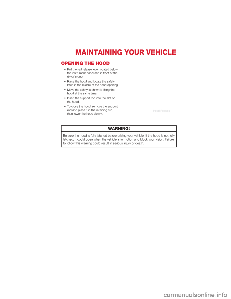
OPENING THE HOOD
• Pull the red release lever located belowthe instrument panel and in front of the
driver’s door.
• Raise the hood and locate the safety latch in the middle of the hood opening.
• Move the safety latch while lifting the hood at the same time.
• Insert the support rod into the slot on the hood.
• To close the hood, remove the support rod and place it in the retaining clip,
then lower the hood slowly.
WARNING!
Be sure the hood is fully latched before driving your vehicle. If the hood is not fully
latched, it could open when the vehicle is in motion and block your vision. Failure
to follow this warning could result in serious injury or death.
MAINTAINING YOUR VEHICLE
55
Page 62 of 76
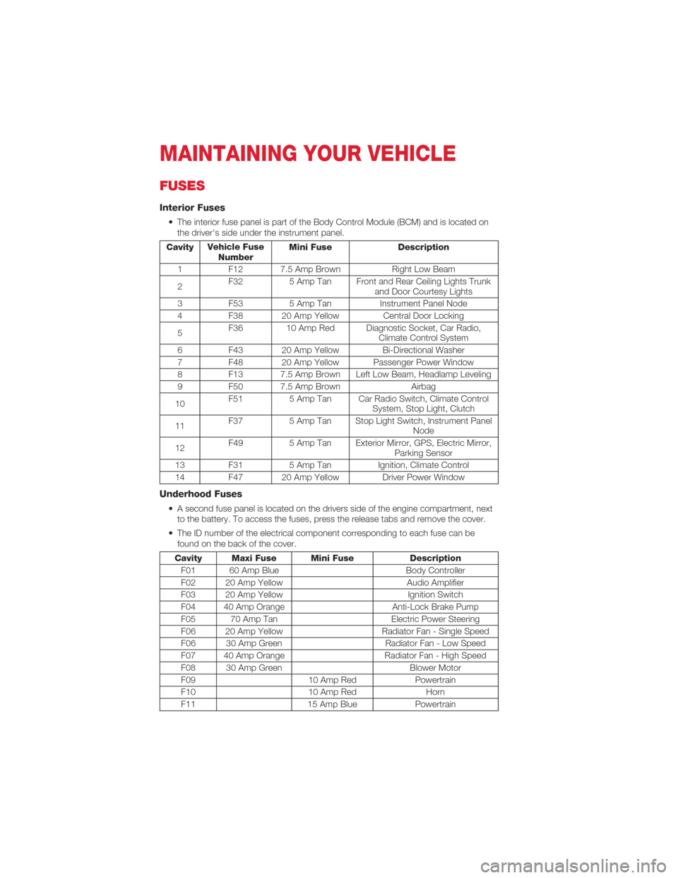
FUSES
Interior Fuses
• The interior fuse panel is part of the Body Control Module (BCM) and is located onthe driver's side under the instrument panel.
Cavity Vehicle Fuse
Number Mini Fuse Description
1 F12 7.5 Amp Brown Right Low Beam
2 F32
5 Amp Tan Front and Rear Ceiling Lights Trunk
and Door Courtesy Lights
3 F53 5 Amp Tan Instrument Panel Node
4 F38 20 Amp Yellow Central Door Locking
5 F36 10 Amp Red Diagnostic Socket, Car Radio,
Climate Control System
6 F43 20 Amp Yellow Bi-Directional Washer
7 F48 20 Amp Yellow Passenger Power Window
8 F13 7.5 Amp Brown Left Low Beam, Headlamp Leveling
9 F50 7.5 Amp Brown Airbag
10 F51
5 Amp Tan Car Radio Switch, Climate Control
System, Stop Light, Clutch
11 F37
5 Amp Tan Stop Light Switch, Instrument Panel
Node
12 F49
5 Amp Tan Exterior Mirror, GPS, Electric Mirror,
Parking Sensor
13 F31 5 Amp TanIgnition, Climate Control
14 F47 20 Amp Yellow Driver Power Window
Underhood Fuses
• A second fuse panel is located on the drivers side of the engine compartment, next to the battery. To access the fuses, press the release tabs and remove the cover.
• The ID number of the electrical component corresponding to each fuse can be found on the back of the cover.
Cavity Maxi Fuse Mini Fuse Description
F01 60 Amp Blue Body Controller
F02 20 Amp Yellow Audio Amplifier
F03 20 Amp Yellow Ignition Switch
F04 40 Amp Orange Anti-Lock Brake Pump
F05 70 Amp Tan Electric Power Steering
F06 20 Amp Yellow Radiator Fan - Single Speed
F06 30 Amp Green Radiator Fan - Low Speed
F07 40 Amp Orange Radiator Fan - High Speed
F08 30 Amp Green Blower Motor
F09 10 Amp RedPowertrain
F10 10 Amp RedHorn
F11 15 Amp BluePowertrain
MAINTAINING YOUR VEHICLE
60