sensor FIAT 500 ABARTH 2014 2.G Owner's Manual
[x] Cancel search | Manufacturer: FIAT, Model Year: 2014, Model line: 500 ABARTH, Model: FIAT 500 ABARTH 2014 2.GPages: 392, PDF Size: 8.74 MB
Page 165 of 392
Personal Settings (Customer-Programmable
Features)
Dimmer
The EVIC display is provided with a light sensor capable
of detecting environmental light conditions and adjust-
ing the brightness of the instruments accordingly.
NOTE:The brightness of the instrument panel may
change while travelling following an event that causes
switching from “day” to “night” conditions (or vice
versa) in the passenger compartment (e.g. in a tunnel, on
avenues in shadows, under bridges, etc.).
To adjust the brightness, proceed as follows:
1. Press the UPor DOWNbutton to set the
required brightness level.
2. Briefly press theMENUbutton to go back to the menu
screen or press and hold theMENU(approximately
one second) to go back to the main screen without
storing settings.
Speed Beep (Speed Limit)
With this function, it is possible to set the car speed limit
(mph or km/h) to immediately alert the driver when the
set limit is exceeded.
To set the speed limit, proceed as follows:
1. Briefly press theMENUbutton. The display will show
the message (Speed Beep).
2. Press the UPor DOWNbutton to select speed
limit activation (On) or deactivation (Off).
3. When the function is activated (On), briefly press the
MENUbutton to display the presently set activation
4
UNDERSTANDING YOUR INSTRUMENT PANEL 163
Page 225 of 392
Cold Weather Operation
To prevent possible engine damage while starting at low
temperatures, this vehicle will inhibit engine cranking
when the ambient temperature is less than –22° F (–30° C)
and the oil temperature sensor reading indicates an
engine block heater has not been used. An externally-
powered electric engine block heater is available as
optional equipment or from your authorized dealer.
The message “plug in engine heater” will be displayed in
the instrument cluster when the ambient temperature is
below 5° F (–15° C) at the time the engine is shut off as a
reminder to avoid possible crank delays at the next cold
start.
CAUTION!
Use of the recommended SAE 5W-40 synthetic en-
gine oil and adhering to the prescribed oil change
intervals is important to prevent engine damage and
ensure satisfactory starting in cold conditions.
Extended Park Starting
NOTE:Extended Park condition occurs when the ve-
hicle has not been started or driven for at least 35 days.
1. Install a battery charger or jumper cables to the battery
to ensure a full battery charge during the crank cycle.
2. Place the ignition in the START position and release it
when the engine starts.
5
STARTING AND OPERATING 223
Page 241 of 392
facing uphill is in forward gear; vehicle backing uphill
is in REVERSE gear).
WARNING!
There may be situations on minor hills with a loaded
vehicle, or while pulling a trailer, when the system
will not activate and slight rolling may occur. This
could cause a collision with another vehicle or object.
Always remember the driver is responsible for brak-
ing the vehicle.
Disabling/Enabling HSA
If you wish to turn the HSA system on or off, it can be
done using the Customer Programmable Features in the
Electronic Vehicle Information Center (EVIC). Refer to
“Electronic Vehicle Information Center (EVIC)” in “Un-
derstanding Your Instrument Panel” for further informa-
tion.
Electronic Stability Control (ESC)
This system enhances directional control and stability of
the vehicle under various driving conditions. ESC cor-
rects for oversteering or understeering of the vehicle by
applying the brake of the appropriate wheel to assist in
counteracting the oversteering or understeering condi-
tion. Engine power may also be reduced to help the
vehicle maintain the desired path. ESC uses sensors in
the vehicle to determine the vehicle path intended by the
driver and compares it to the actual path of the vehicle.
When the actual path does not match the intended path,
ESC applies the brake of the appropriate wheel to assist
in counteracting the oversteer or understeer condition.
•Oversteer - when the vehicle is turning more than
appropriate for the steering wheel position.
•Understeer - when the vehicle is turning less than
appropriate for the steering wheel position.
5
STARTING AND OPERATING 239
Page 268 of 392
CAUTION!
•The TPMS has been optimized for the original
equipment tires and wheels. TPMS pressures and
warnings have been established for the tire size
equipped on your vehicle. Undesirable system op-
eration or sensor damage may result when using
replacement equipment that is not of the same size,
type, and/or style. Aftermarket wheels can cause
sensor damage. Do not use aftermarket tire sealants
or balance beads if your vehicle is equipped with a
TPMS, as damage to the sensors may result.
•After inspecting or adjusting the tire pressure,
always reinstall the valve stem cap. This will
prevent moisture and dirt from entering the valve
stem, which could damage the Tire Pressure Moni-
toring Sensor.
NOTE:
•The TPMS is not intended to replace normal tire care
and maintenance, or to provide warning of a tire
failure or condition.
•The TPMS should not be used as a tire pressure gauge
while adjusting your tire pressure.
•Driving on a significantly under-inflated tire causes
the tire to overheat and can lead to tire failure.
Under-inflation also reduces fuel efficiency and tire
tread life, and may affect the vehicle’s handling and
stopping ability.
•The TPMS is not a substitute for proper tire mainte-
nance, and it is the driver ’s responsibility to maintain
correct tire pressure using an accurate tire gauge, even
if under-inflation has not reached the level to trigger
illumination of the Tire Pressure Monitoring Telltale
Light.
266 STARTING AND OPERATING
Page 269 of 392
•Seasonal temperature changes will affect tire pressure,
and the TPMS will monitor the actual tire pressure in
the tire.
Base System
This is the TPMS warning indicator located in the
instrument cluster.
The TPMS uses wireless technology with wheel rim
mounted electronic sensors to monitor tire pressure lev-
els. Sensors, mounted to each wheel as part of the valve
stem, transmit tire pressure readings to the Receiver
Module.
NOTE:It is particularly important for you to check the
tire pressure in all of the tires on your vehicle regularly
and to maintain the proper pressure.
The TPMS consists of the following components:
•Receiver Module
•Four Tire Pressure Monitoring Sensors
•Tire Pressure Monitoring Telltale Light
Tire Pressure Monitoring Low Pressure Warnings
The Tire Pressure Monitoring Telltale Light will illumi-
nate in the instrument cluster, an audible chime will be
activated, and the “Check left or right front/rear tire
xxx.x psi” text message will display when one or more of
the four active road tire pressures are low. Should this
occur, you should stop as soon as possible, check the
inflation pressure of each tire on your vehicle, and inflate
each tire to the vehicle’s recommended cold placard
pressure value. The system will automatically update
and the Tire Pressure Monitoring Light will extinguish
once the updated tire pressures have been received. The
5
STARTING AND OPERATING 267
Page 270 of 392
vehicle may need to be driven for up to 20 minutes above
15 mph (24 km/h) to receive this information.
Check TPMS Warnings
The Tire Pressure Monitoring Telltale Light will flash on
and off for 75 seconds and remain on solid when a system
fault is detected, and the “Tire Pressure Monitoring
Unavailable” text message will display. If the ignition key
is cycled, this sequence will repeat providing the system
fault still exists. The Tire Pressure Monitoring Telltale
Light will turn off when the fault condition no longer
exists. A system fault can occur with any of the following
scenarios:
1. Jamming due to electronic devices or driving next to
facilities emitting the same radio frequencies as the
TPM sensors.
2. Installing some form of aftermarket window tinting
that affects radio wave signals.
3. Snow or ice around the wheels or wheel housings.
4. Using tire chains on the vehicle.
5. Using wheels/tires not equipped with TPM sensors.
NOTE:Your vehicle may be equipped with a compact
spare wheel and tire assembly.
1. The compact spare tire does not have a tire pressure
monitoring sensor. Therefore, the TPMS will not moni-
tor the tire pressure in the compact spare tire.
2. If you install the compact spare tire in place of a road
tire that has a pressure below the low-pressure warn-
ing limit, upon the next ignition key cycle, a chime will
sound and the Tire Pressure Monitoring Telltale Light
and the “Check Tire Pressure” message will still turn
ON due to the low tire.
3. However, after driving the vehicle for up to 20 min-
utes above 15 mph (24 km/h), the Tire Pressure
268 STARTING AND OPERATING
Page 272 of 392
The tire pressure sensors are covered under one of the
following licenses:
United StatesMRXC4W4MA4
Canada2546A-C4W4MA4
(Single)
FUEL REQUIREMENTS
This engine is designed to meet all emis-
sion regulations and provide satisfactory
fuel economy and performance when us-
ing high-quality unleaded “regular” gaso-
line with a minimum octane rating of 87.
For optimum performance and fuel economy the use of
91 octane or higher is recommended.
Light spark knock at low engine speeds is not harmful to
your engine. However, continued heavy spark knock at
high speeds can cause damage and immediate service is
required.
Poor quality gasoline can cause problems such as hard
starting, stalling and hesitations. If you experience these
symptoms, try another brand of gasoline (with the ap-
propriate octane rating for your engine) before consider-
ing service for the vehicle.
Reformulated Gasoline
Many areas of the country require the use of cleaner
burning gasoline referred to as “Reformulated Gasoline.”
Reformulated gasolines contain oxygenates and are spe-
cifically blended to reduce vehicle emissions and im-
prove air quality.
270 STARTING AND OPERATING
Page 286 of 392
TIREFIT Usage Precautions
•Using the TIREFIT sealant may cause the Tire Pressure
Monitoring System (TPMS) to become inoperable. It is
recommended that you take your vehicle to an autho-
rized dealer to have the sensor function checked.
•Replace the TIREFIT Sealant Bottle (1) and Sealant
Hose (6) prior to the expiration date (printed at the
lower right hand corner on the bottle label) to assure
optimum operation of the system. Refer to “Sealing a
Tire with TIREFIT” section (F) “Sealant Bottle and
Hose Replacement.”
•The Sealant Bottle (1) and Sealant Hose (6) are a one
tire application use and need to be replaced after each
use. Always replace these components immediately at
your original equipment vehicle dealer.
•When the TIREFIT sealant is in a liquid form, clean
water, and a damp cloth will remove the material from
the vehicle or tire and wheel components. Once the
sealant dries, it can easily be peeled off and properly
discarded.
•For optimum performance, make sure the valve stem
on the wheel is free of debris before connecting the
TIREFIT kit.
•You can use the TIREFIT air pump to inflate bicycle
tires. The kit also comes with two needles, located in
the Accessory Storage Compartment (on the bottom of
the air pump) for inflating sport balls, rafts, or similar
inflatable items. However, use only the Air Pump Hose
(7) and make sure the Mode Select Knob (5) is in the
Air Mode when inflating such items to avoid injecting
sealant into them. The TIREFIT Sealant is only in-
tended to seal punctures less than¼” (6 mm) diameter
in the tread of your vehicle.
•Do not lift or carry the TIREFIT kit by the hoses.
284 WHAT TO DO IN EMERGENCIES
Page 349 of 392
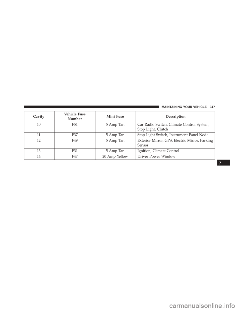
CavityVehicle Fuse
NumberMini FuseDescription
10F515 Amp Tan Car Radio Switch, Climate Control System,
Stop Light, Clutch
11F375 Amp Tan Stop Light Switch, Instrument Panel Node
12F495 Amp Tan Exterior Mirror, GPS, Electric Mirror, Parking
Sensor
13F315 Amp Tan Ignition, Climate Control
14F4720 Amp Yellow Driver Power Window
7
MAINTAINING YOUR VEHICLE 347