lock FIAT 500 ABARTH 2015 2.G Owner's Manual
[x] Cancel search | Manufacturer: FIAT, Model Year: 2015, Model line: 500 ABARTH, Model: FIAT 500 ABARTH 2015 2.GPages: 108, PDF Size: 2.63 MB
Page 25 of 108
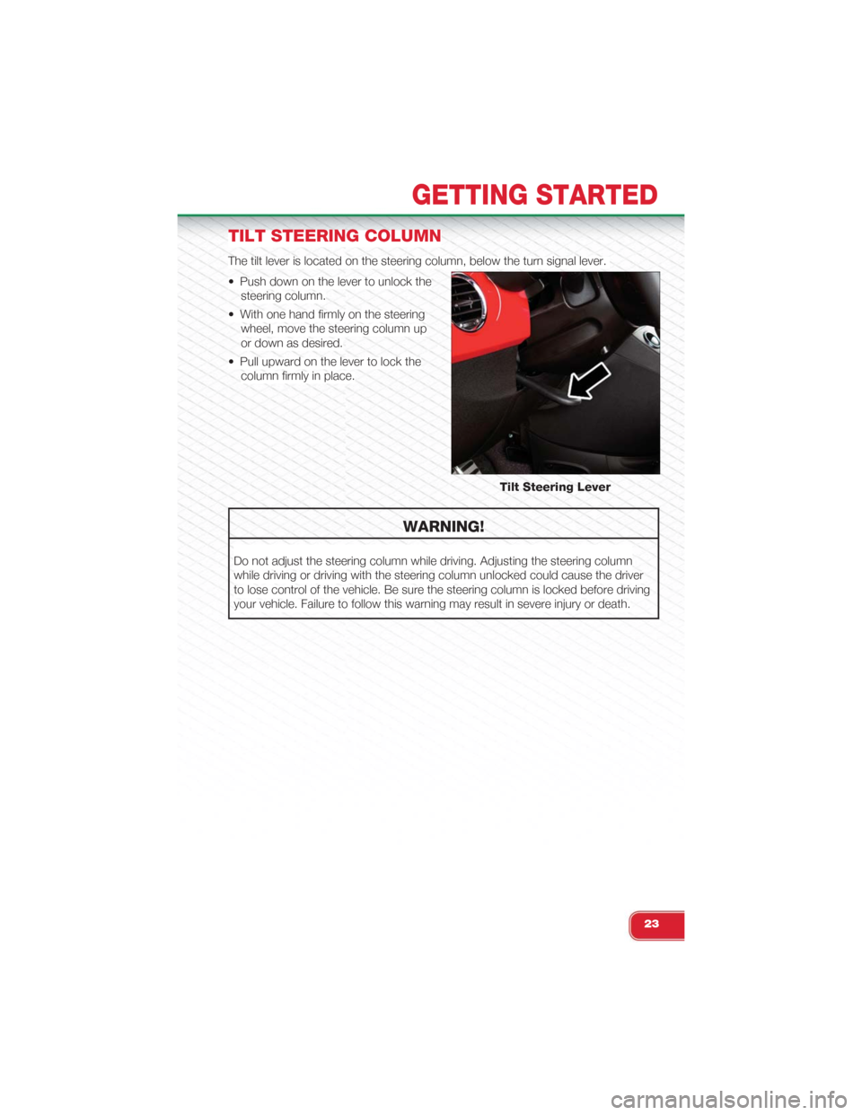
TILT STEERING COLUMN
The tilt lever is located on the steering column, below the turn signal lever.
• Push down on the lever to unlock the
steering column.
• With one hand firmly on the steering
wheel, move the steering column up
or down as desired.
• Pull upward on the lever to lock the
column firmly in place.
WARNING!
Do not adjust the steering column while driving. Adjusting the steering column
while driving or driving with the steering column unlocked could cause the driver
to lose control of the vehicle. Be sure the steering column is locked before driving
your vehicle. Failure to follow this warning may result in severe injury or death.
Tilt Steering Lever
GETTING STARTED
23
Page 27 of 108
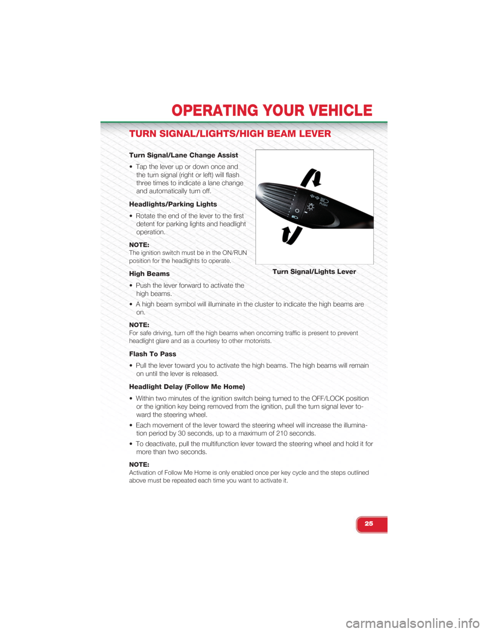
TURN SIGNAL/LIGHTS/HIGH BEAM LEVER
Turn Signal/Lane Change Assist
• Tap the lever up or down once and
the turn signal (right or left) will flash
three times to indicate a lane change
and automatically turn off.
Headlights/Parking Lights
• Rotate the end of the lever to the first
detent for parking lights and headlight
operation.
NOTE:The ignition switch must be in the ON/RUNposition for the headlights to operate.
High Beams
• Push the lever forward to activate the
high beams.
• A high beam symbol will illuminate in the cluster to indicate the high beams are
on.
NOTE:For safe driving, turn off the high beams when oncoming traffic is present to preventheadlight glare and as a courtesy to other motorists.
Flash To Pass
• Pull the lever toward you to activate the high beams. The high beams will remain
on until the lever is released.
Headlight Delay (Follow Me Home)
• Within two minutes of the ignition switch being turned to the OFF/LOCK position
or the ignition key being removed from the ignition, pull the turn signal lever to-
ward the steering wheel.
• Each movement of the lever toward the steering wheel will increase the illumina-
tion period by 30 seconds, up to a maximum of 210 seconds.
• To deactivate, pull the multifunction lever toward the steering wheel and hold it for
more than two seconds.
NOTE:Activation of Follow Me Home is only enabled once per key cycle and the steps outlinedabove must be repeated each time you want to activate it.
Turn Signal/Lights Lever
OPERATING YOUR VEHICLE
25
Page 39 of 108
WIND BUFFETING
• Wind buffeting can be described as a helicopter-type percussion sound. If buffet-
ing occurs with the windows down, adjust one or both windows up or down
slightly.
• If buffeting occurs with the sunroof open, adjust the sunroof opening, or adjust
any window. This will minimize buffeting.
ENGINE BLOCK HEATER
• To prevent possible engine damage while starting at low temperatures, this ve-
hicle will inhibit engine cranking when the ambient temperature is less than –22°
F (–30° C) and the oil temperature sensor reading indicates an engine block
heater has not been used. An externally-powered electric engine block heater is
available as optional equipment or from your authorized dealer.
• The message "plug in engine heater" will be displayed in the instrument cluster
when the ambient temperature is below 5° F (–15° C) at the time the engine is
shut off as a reminder to avoid possible crank delays at the next cold start.
OPERATING YOUR VEHICLE
37
Page 53 of 108
PROGRAMMABLE FEATURES
Electronic Vehicle Information Center (EVIC)
• The EVIC can be used to program the following Personal Settings. Push the
MENU button until menu is displayed, then push the UPor DOWNbut-
tons to scroll through the settings.
• Once the menu setting is shown in the EVIC display push the MENU button to
access the setting and use the UPor DOWNbuttons to change the
current setting. The menu includes the following functions:
• Speed Beep • Buzzer Volume
• Trip B Data • Button Volume
• Set Time • Hill Start Assist
• Set Date • Daylights (D.R.L)
• See Radio (Repeat Audio Informa-tion)• Hill Start
• Speed Display • Tire Pressure
• Autoclose • Unlock Driver Door First
• Units • Unlock All Doors
• Language • Exit Menu
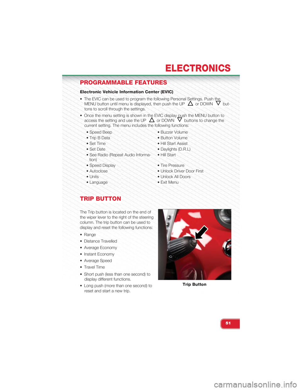
TRIP BUTTON
The Trip button is located on the end of
the wiper lever to the right of the steering
column. The trip button can be used to
display and reset the following functions:
• Range
• Distance Travelled
• Average Economy
• Instant Economy
• Average Speed
• Travel Time
• Short push (less than one second) to
display different functions.
• Long push (more than one second) to
reset and start a new trip.
Trip Button
ELECTRONICS
51
Page 57 of 108
ROADSIDE ASSISTANCE
• If your Abarth requires jump start assistance, out of gas/fuel delivery, tire service,
lockout service or towing due to a defect covered under the Basic Limited War-
ranty, dial toll-free 1-888-242-6342 or 1-800-363-4869 for Canadian Residents.
See your Warranty booklet for further details.
• Provide your name, vehicle identification number and license plate number.
• Provide your location, including telephone number, from which you are calling.
• Briefly describe the nature of the problem and answer a few simple questions.
• You will be given the name of the service provider and an estimated time of ar-
rival. If you feel you are in an “unsafe situation,” please let us know. With your
consent, we will contact local police or safety authorities.
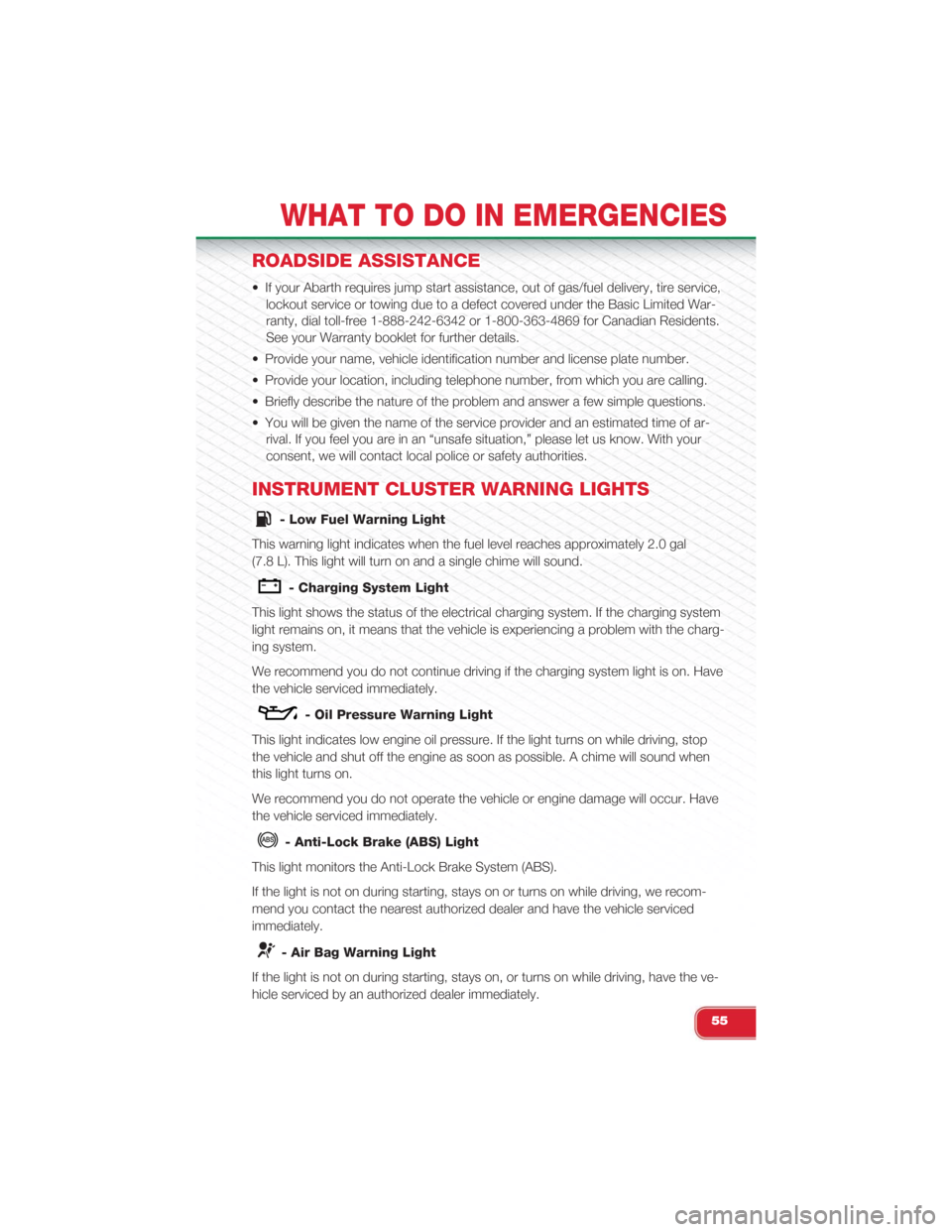
INSTRUMENT CLUSTER WARNING LIGHTS
- Low Fuel Warning Light
This warning light indicates when the fuel level reaches approximately 2.0 gal
(7.8 L). This light will turn on and a single chime will sound.
- Charging System Light
This light shows the status of the electrical charging system. If the charging system
light remains on, it means that the vehicle is experiencing a problem with the charg-
ing system.
We recommend you do not continue driving if the charging system light is on. Have
the vehicle serviced immediately.
- Oil Pressure Warning Light
This light indicates low engine oil pressure. If the light turns on while driving, stop
the vehicle and shut off the engine as soon as possible. A chime will sound when
this light turns on.
We recommend you do not operate the vehicle or engine damage will occur. Have
the vehicle serviced immediately.
- Anti-Lock Brake (ABS) Light
This light monitors the Anti-Lock Brake System (ABS).
If the light is not on during starting, stays on or turns on while driving, we recom-
mend you contact the nearest authorized dealer and have the vehicle serviced
immediately.
- Air Bag Warning Light
If the light is not on during starting, stays on, or turns on while driving, have the ve-
hicle serviced by an authorized dealer immediately.
WHAT TO DO IN EMERGENCIES
55
Page 60 of 108
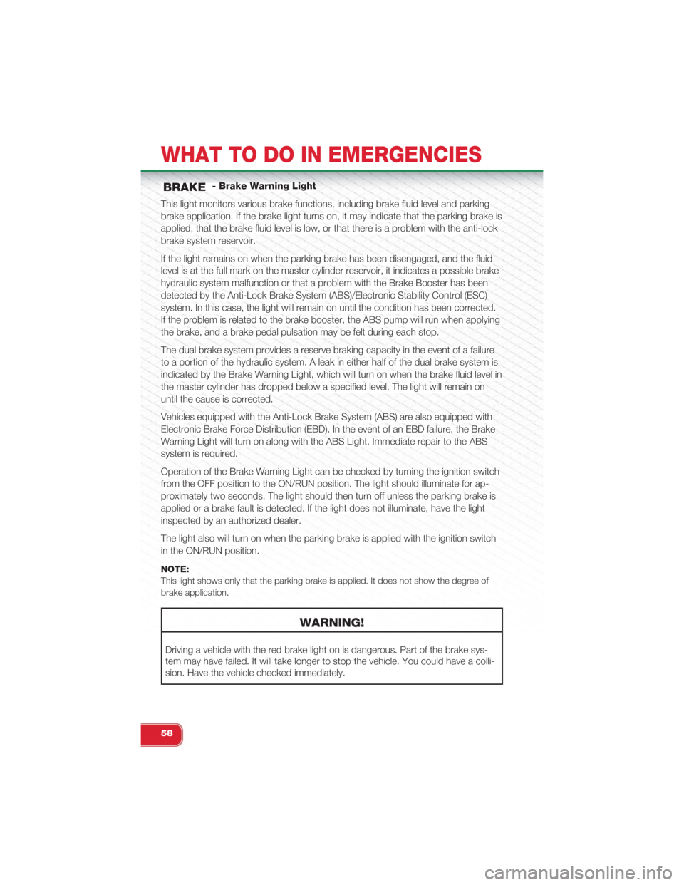
- Brake Warning Light
This light monitors various brake functions, including brake fluid level and parking
brake application. If the brake light turns on, it may indicate that the parking brake is
applied, that the brake fluid level is low, or that there is a problem with the anti-lock
brake system reservoir.
If the light remains on when the parking brake has been disengaged, and the fluid
level is at the full mark on the master cylinder reservoir, it indicates a possible brake
hydraulic system malfunction or that a problem with the Brake Booster has been
detected by the Anti-Lock Brake System (ABS)/Electronic Stability Control (ESC)
system. In this case, the light will remain on until the condition has been corrected.
If the problem is related to the brake booster, the ABS pump will run when applying
the brake, and a brake pedal pulsation may be felt during each stop.
The dual brake system provides a reserve braking capacity in the event of a failure
to a portion of the hydraulic system. A leak in either half of the dual brake system is
indicated by the Brake Warning Light, which will turn on when the brake fluid level in
the master cylinder has dropped below a specified level. The light will remain on
until the cause is corrected.
Vehicles equipped with the Anti-Lock Brake System (ABS) are also equipped with
Electronic Brake Force Distribution (EBD). In the event of an EBD failure, the Brake
Warning Light will turn on along with the ABS Light. Immediate repair to the ABS
system is required.
Operation of the Brake Warning Light can be checked by turning the ignition switch
from the OFF position to the ON/RUN position. The light should illuminate for ap-
proximately two seconds. The light should then turn off unless the parking brake is
applied or a brake fault is detected. If the light does not illuminate, have the light
inspected by an authorized dealer.
The light also will turn on when the parking brake is applied with the ignition switch
in the ON/RUN position.
NOTE:
This light shows only that the parking brake is applied. It does not show the degree of
brake application.
WARNING!
Driving a vehicle with the red brake light on is dangerous. Part of the brake sys-
tem may have failed. It will take longer to stop the vehicle. You could have a colli-
sion. Have the vehicle checked immediately.
WHAT TO DO IN EMERGENCIES
58
Page 63 of 108
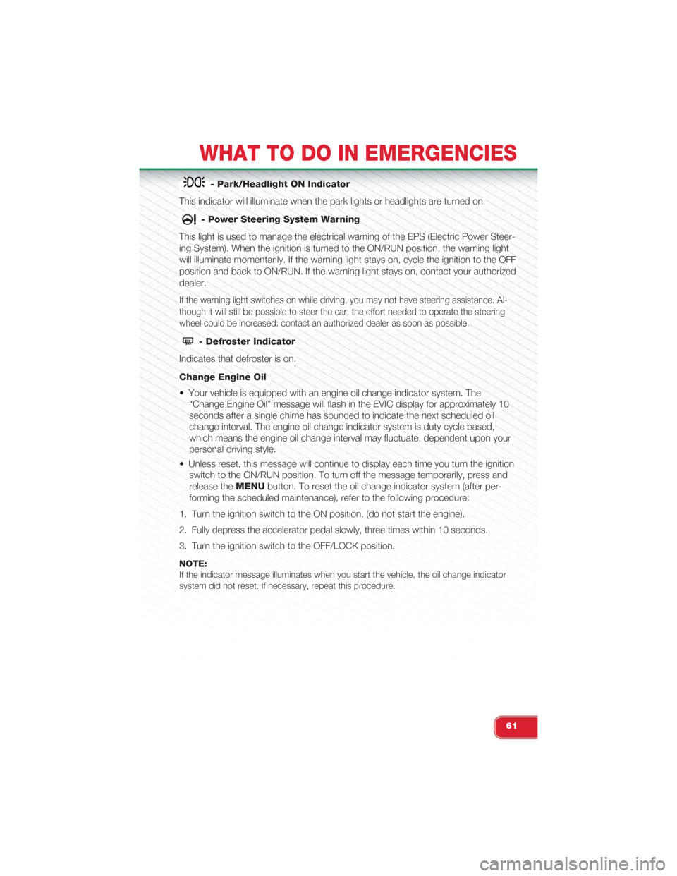
- Park/Headlight ON Indicator
This indicator will illuminate when the park lights or headlights are turned on.
- Power Steering System Warning
This light is used to manage the electrical warning of the EPS (Electric Power Steer-
ing System). When the ignition is turned to the ON/RUN position, the warning light
will illuminate momentarily. If the warning light stays on, cycle the ignition to the OFF
position and back to ON/RUN. If the warning light stays on, contact your authorized
dealer.
If the warning light switches on while driving, you may not have steering assistance. Al-
though it will still be possible to steer the car, the effort needed to operate the steering
wheel could be increased: contact an authorized dealer as soon as possible.
- Defroster Indicator
Indicates that defroster is on.
Change Engine Oil
• Your vehicle is equipped with an engine oil change indicator system. The
“Change Engine Oil” message will flash in the EVIC display for approximately 10
seconds after a single chime has sounded to indicate the next scheduled oil
change interval. The engine oil change indicator system is duty cycle based,
which means the engine oil change interval may fluctuate, dependent upon your
personal driving style.
• Unless reset, this message will continue to display each time you turn the ignition
switch to the ON/RUN position. To turn off the message temporarily, press and
release theMENUbutton. To reset the oil change indicator system (after per-
forming the scheduled maintenance), refer to the following procedure:
1. Turn the ignition switch to the ON position. (do not start the engine).
2. Fully depress the accelerator pedal slowly, three times within 10 seconds.
3. Turn the ignition switch to the OFF/LOCK position.
NOTE:If the indicator message illuminates when you start the vehicle, the oil change indicatorsystem did not reset. If necessary, repeat this procedure.
WHAT TO DO IN EMERGENCIES
61
Page 69 of 108
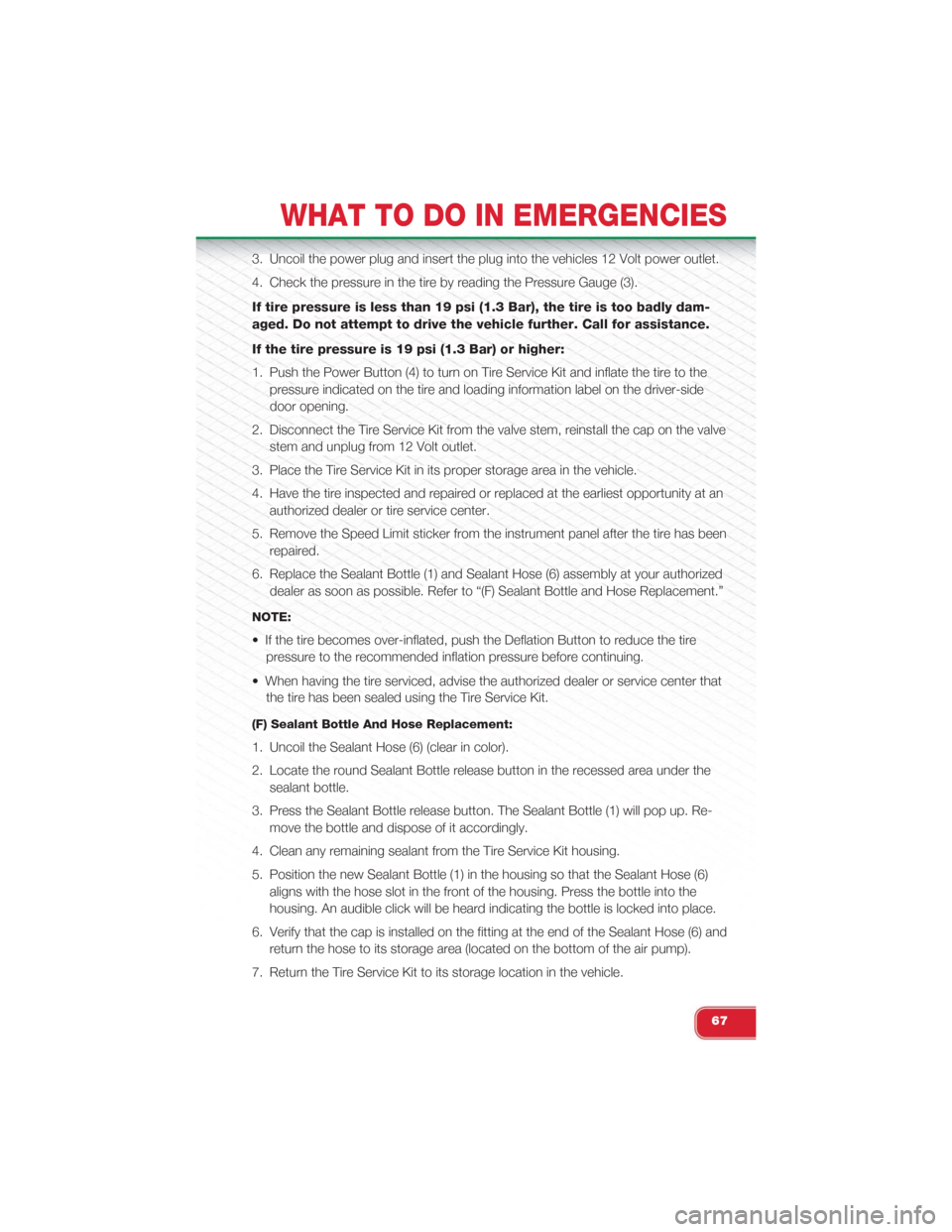
3. Uncoil the power plug and insert the plug into the vehicles 12 Volt power outlet.
4. Check the pressure in the tire by reading the Pressure Gauge (3).
If tire pressure is less than 19 psi (1.3 Bar), the tire is too badly dam-
aged. Do not attempt to drive the vehicle further. Call for assistance.
If the tire pressure is 19 psi (1.3 Bar) or higher:
1. Push the Power Button (4) to turn on Tire Service Kit and inflate the tire to the
pressure indicated on the tire and loading information label on the driver-side
door opening.
2. Disconnect the Tire Service Kit from the valve stem, reinstall the cap on the valve
stem and unplug from 12 Volt outlet.
3. Place the Tire Service Kit in its proper storage area in the vehicle.
4. Have the tire inspected and repaired or replaced at the earliest opportunity at an
authorized dealer or tire service center.
5. Remove the Speed Limit sticker from the instrument panel after the tire has been
repaired.
6. Replace the Sealant Bottle (1) and Sealant Hose (6) assembly at your authorized
dealer as soon as possible. Refer to “(F) Sealant Bottle and Hose Replacement.”
NOTE:
• If the tire becomes over-inflated, push the Deflation Button to reduce the tire
pressure to the recommended inflation pressure before continuing.
• When having the tire serviced, advise the authorized dealer or service center that
the tire has been sealed using the Tire Service Kit.
(F) Sealant Bottle And Hose Replacement:
1. Uncoil the Sealant Hose (6) (clear in color).
2. Locate the round Sealant Bottle release button in the recessed area under the
sealant bottle.
3. Press the Sealant Bottle release button. The Sealant Bottle (1) will pop up. Re-
move the bottle and dispose of it accordingly.
4. Clean any remaining sealant from the Tire Service Kit housing.
5. Position the new Sealant Bottle (1) in the housing so that the Sealant Hose (6)
aligns with the hose slot in the front of the housing. Press the bottle into the
housing. An audible click will be heard indicating the bottle is locked into place.
6. Verify that the cap is installed on the fitting at the end of the Sealant Hose (6) and
return the hose to its storage area (located on the bottom of the air pump).
7. Return the Tire Service Kit to its storage location in the vehicle.
WHAT TO DO IN EMERGENCIES
67
Page 71 of 108
JUMP-STARTING PROCEDURE
• If your vehicle has a discharged battery, it can be jump-started using a set of
jumper cables and a battery in another vehicle or by using a portable battery
booster pack. Jump-starting can be dangerous if done improperly so please fol-
low the procedures in this section carefully.
NOTE:When using a portable battery booster pack, follow the manufacturer’s operating instruc-tions and precautions.
Preparations For Jump-Start
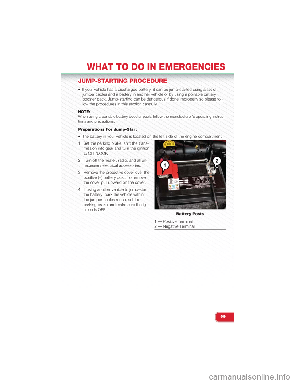
• The battery in your vehicle is located on the left side of the engine compartment.
1. Set the parking brake, shift the trans-
mission into gear and turn the ignition
to OFF/LOCK.
2. Turn off the heater, radio, and all un-
necessary electrical accessories.
3. Remove the protective cover over the
positive (+) battery post. To remove
the cover pull upward on the cover.
4. If using another vehicle to jump-start
the battery, park the vehicle within
the jumper cables reach, set the
parking brake and make sure the ig-
nition is OFF.Battery Posts
1 — Positive Terminal2 — Negative Terminal
WHAT TO DO IN EMERGENCIES
69
Page 75 of 108
ENHANCED ACCIDENT RESPONSE SYSTEM
In the event of an impact causing air bag deployment, if the communication network
remains intact, and the power remains intact, depending on the nature of the event
the Occupant Restraint Controller (ORC) will determine whether to have the En-
hanced Accident Response System perform the following functions:
• Cut off fuel to the engine.
• Flash hazard lights as long as the battery has power or until the ignition key is
turned off.
• Turn on the interior lights, which remain on as long as the battery has power or
until the ignition key is removed.
• Unlock the doors automatically.
After the event occurs, when the system is active, the message "Fuel Cutoff See
Handbook" is displayed.
Carefully check the vehicle for fuel leaks in the engine compartment and on the
ground near the engine compartment and fuel tank before resetting the system and
starting the engine.
NOTE:In order to start the engine and move the vehicle to a safe location after an impact, theSystem Reset Procedure must be completed.
System Reset Procedure
After an impact causing air bag deployment, the left and right turn signal lights, located in
the instrument panel cluster, will both be blinking until the ignition is turned off.
WHAT TO DO IN EMERGENCIES
73