electronic FIAT 500 ABARTH 2015 2.G Owner's Manual
[x] Cancel search | Manufacturer: FIAT, Model Year: 2015, Model line: 500 ABARTH, Model: FIAT 500 ABARTH 2015 2.GPages: 108, PDF Size: 2.63 MB
Page 51 of 108
iPod®/USB/MP3 CONTROL
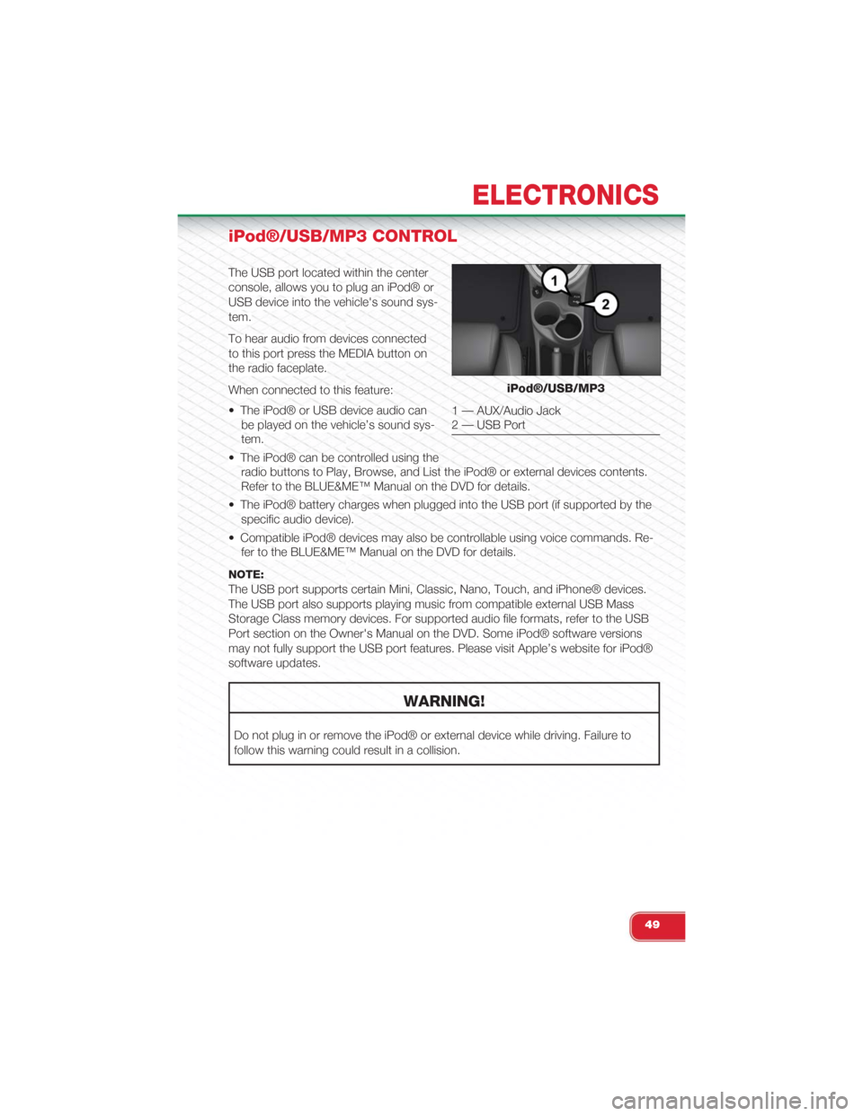
The USB port located within the center
console, allows you to plug an iPod® or
USB device into the vehicle's sound sys-
tem.
To hear audio from devices connected
to this port press the MEDIA button on
the radio faceplate.
When connected to this feature:
• The iPod® or USB device audio can
be played on the vehicle’s sound sys-
tem.
• The iPod® can be controlled using the
radio buttons to Play, Browse, and List the iPod® or external devices contents.
Refer to the BLUE&ME™ Manual on the DVD for details.
• The iPod® battery charges when plugged into the USB port (if supported by the
specific audio device).
• Compatible iPod® devices may also be controllable using voice commands. Re-
fer to the BLUE&ME™ Manual on the DVD for details.
NOTE:
The USB port supports certain Mini, Classic, Nano, Touch, and iPhone® devices.
The USB port also supports playing music from compatible external USB Mass
Storage Class memory devices. For supported audio file formats, refer to the USB
Port section on the Owner's Manual on the DVD. Some iPod® software versions
may not fully support the USB port features. Please visit Apple’s website for iPod®
software updates.
WARNING!
Do not plug in or remove the iPod® or external device while driving. Failure to
follow this warning could result in a collision.
iPod®/USB/MP3
1 — AUX/Audio Jack2 — USB Port
ELECTRONICS
49
Page 52 of 108
ELECTRONIC VEHICLE INFORMATION CENTER
(EVIC)
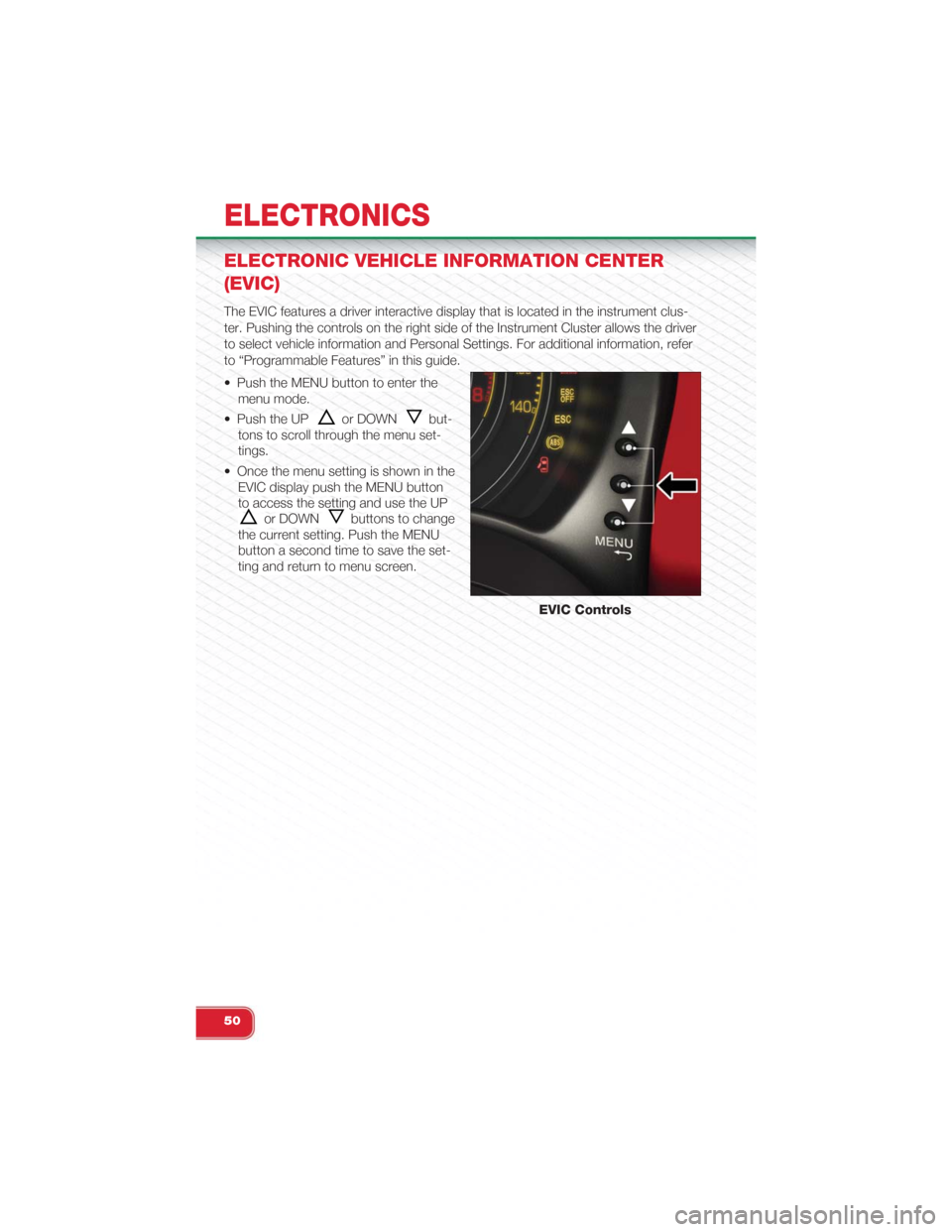
The EVIC features a driver interactive display that is located in the instrument clus-
ter. Pushing the controls on the right side of the Instrument Cluster allows the driver
to select vehicle information and Personal Settings. For additional information, refer
to “Programmable Features” in this guide.
• Push the MENU button to enter the
menu mode.
• Push the UPor DOWNbut-
tons to scroll through the menu set-
tings.
• Once the menu setting is shown in the
EVIC display push the MENU button
to access the setting and use the UP
or DOWNbuttons to change
the current setting. Push the MENU
button a second time to save the set-
ting and return to menu screen.
EVIC Controls
ELECTRONICS
50
Page 53 of 108
PROGRAMMABLE FEATURES
Electronic Vehicle Information Center (EVIC)
• The EVIC can be used to program the following Personal Settings. Push the
MENU button until menu is displayed, then push the UPor DOWNbut-
tons to scroll through the settings.
• Once the menu setting is shown in the EVIC display push the MENU button to
access the setting and use the UPor DOWNbuttons to change the
current setting. The menu includes the following functions:
• Speed Beep • Buzzer Volume
• Trip B Data • Button Volume
• Set Time • Hill Start Assist
• Set Date • Daylights (D.R.L)
• See Radio (Repeat Audio Informa-tion)• Hill Start
• Speed Display • Tire Pressure
• Autoclose • Unlock Driver Door First
• Units • Unlock All Doors
• Language • Exit Menu
TRIP BUTTON
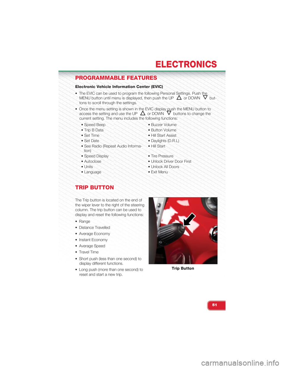
The Trip button is located on the end of
the wiper lever to the right of the steering
column. The trip button can be used to
display and reset the following functions:
• Range
• Distance Travelled
• Average Economy
• Instant Economy
• Average Speed
• Travel Time
• Short push (less than one second) to
display different functions.
• Long push (more than one second) to
reset and start a new trip.
Trip Button
ELECTRONICS
51
Page 54 of 108
New Trip
• A new trip can be reset or restarted by:
• “Manual” resetting by the user, by pushing the Trip button;
• “Automatically” resetting, when the “Trip distance” reaches 9999.9 miles or
when the “Travel time” reaches 99.59 (99 hours and 59 minutes);
• After disconnecting/reconnecting the battery.
Trip A
• Shows the total distance traveled for Trip A since the last reset.
Trip B
• Shows the total distance traveled for Trip B since the last reset.
Start Of Trip Procedure
• With the ignition key on, push and hold the TRIP button for over one second to
reset Trip A or Trip B.
Exit Trip
• The Trip function is over when all the values have been displayed or holding the
MENU button for longer than one second.
• Briefly push the MENU button to go back to the main screen or push and hold
the MENU button (approximately one second) to go back to the main screen
without storing settings.
ELECTRONICS
52
Page 55 of 108
POWER OUTLET
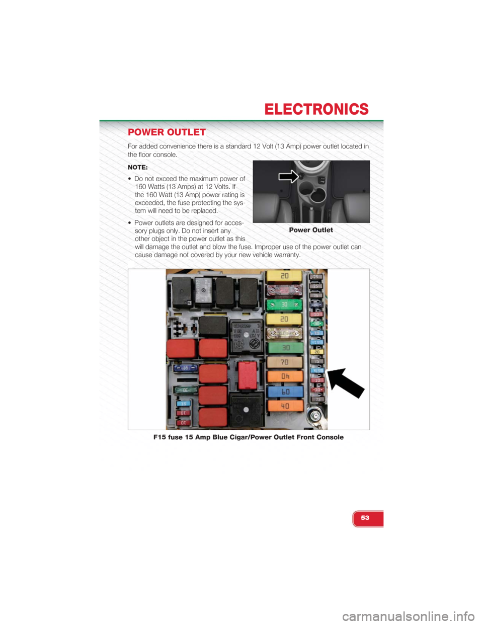
For added convenience there is a standard 12 Volt (13 Amp) power outlet located in
the floor console.
NOTE:
• Do not exceed the maximum power of
160 Watts (13 Amps) at 12 Volts. If
the 160 Watt (13 Amp) power rating is
exceeded, the fuse protecting the sys-
tem will need to be replaced.
• Power outlets are designed for acces-
sory plugs only. Do not insert any
other object in the power outlet as this
will damage the outlet and blow the fuse. Improper use of the power outlet can
cause damage not covered by your new vehicle warranty.
Power Outlet
F15 fuse 15 Amp Blue Cigar/Power Outlet Front Console
ELECTRONICS
53
Page 60 of 108
- Brake Warning Light
This light monitors various brake functions, including brake fluid level and parking
brake application. If the brake light turns on, it may indicate that the parking brake is
applied, that the brake fluid level is low, or that there is a problem with the anti-lock
brake system reservoir.
If the light remains on when the parking brake has been disengaged, and the fluid
level is at the full mark on the master cylinder reservoir, it indicates a possible brake
hydraulic system malfunction or that a problem with the Brake Booster has been
detected by the Anti-Lock Brake System (ABS)/Electronic Stability Control (ESC)
system. In this case, the light will remain on until the condition has been corrected.
If the problem is related to the brake booster, the ABS pump will run when applying
the brake, and a brake pedal pulsation may be felt during each stop.
The dual brake system provides a reserve braking capacity in the event of a failure
to a portion of the hydraulic system. A leak in either half of the dual brake system is
indicated by the Brake Warning Light, which will turn on when the brake fluid level in
the master cylinder has dropped below a specified level. The light will remain on
until the cause is corrected.
Vehicles equipped with the Anti-Lock Brake System (ABS) are also equipped with
Electronic Brake Force Distribution (EBD). In the event of an EBD failure, the Brake
Warning Light will turn on along with the ABS Light. Immediate repair to the ABS
system is required.
Operation of the Brake Warning Light can be checked by turning the ignition switch
from the OFF position to the ON/RUN position. The light should illuminate for ap-
proximately two seconds. The light should then turn off unless the parking brake is
applied or a brake fault is detected. If the light does not illuminate, have the light
inspected by an authorized dealer.
The light also will turn on when the parking brake is applied with the ignition switch
in the ON/RUN position.
NOTE:
This light shows only that the parking brake is applied. It does not show the degree of
brake application.
WARNING!
Driving a vehicle with the red brake light on is dangerous. Part of the brake sys-
tem may have failed. It will take longer to stop the vehicle. You could have a colli-
sion. Have the vehicle checked immediately.
WHAT TO DO IN EMERGENCIES
58
Page 61 of 108
- Malfunction Indicator Light (MIL)
Certain conditions, such as a loose or missing gas cap, poor fuel quality, etc., may
illuminate the MIL after engine start. The vehicle should be serviced if the light stays
on through several typical driving cycles. In most situations, the vehicle will drive
normally and not require towing.
If the MIL flashes when the engine is running, serious conditions may exist that
could lead to immediate loss of power or severe catalytic converter damage. We
recommend you do not operate the vehicle. Have the vehicle serviced immediately.
- Electronic Stability Control (ESC) Activation / Malfunction
Indicator Light
The “ESC Activation/Malfunction Indicator Light” in the instrument cluster will come
on for four seconds when the ignition switch is turned to the ON/RUN position. If
the “ESC Activation/Malfunction Indicator Light” comes on continuously with the
engine running, a malfunction has been detected in the ESC system. If this light re-
mains on, see your authorized dealer as soon as possible to have the problem diag-
nosed and corrected.
NOTE:
• The “ESC Off Indicator Light” and the “ESC Activation/Malfunction Indicator
Light” come on momentarily each time the ignition switch is turned to ON/RUN.
• Each time the ignition is turned to ON/RUN, the ESC system will be ON even if it
was turned off previously.
• ESC Activation/Malfunction Light can blink during a ESC or TC intervention.
- Generic Warning Light
The Generic Warning Light will illuminate if any of the following conditions occur: Oil
Change Request, Engine Oil Pressure Sensor Failure, External Light Failure, Fuel
Cut-Off Not Available, Parking Sensor Failure, DST System Failure.
- Electronic Throttle Control (ETC) Indicator Light
This light informs you of a problem with the system.
If a problem is detected, the light will come on while the engine is running. Cycle the
ignition when the vehicle has completely stopped and the shift lever is placed in the
PARK position; the light should turn off.
If the light remains lit with the engine running, your vehicle will usually be drivable.
However, see an authorized dealer immediately. If the light is flashing when the en-
gine is running, immediate service is required, and you may experience reduced
performance, an elevated/rough idle or engine stall, and your vehicle may require
towing.
WHAT TO DO IN EMERGENCIES
59
Page 62 of 108
INSTRUMENT CLUSTER INDICATOR LIGHTS
- Turn Signal Indicator
The arrows will flash with the exterior turn signals when the turn signal lever is oper-
ated. A tone will chime, and a EVIC message will appear if either turn signal is left on
for more than 1 mile (1.6 km).
NOTE:
If either indicator flashes at a rapid rate, check for a defective outside light bulb.
- High Beam Indicator
Indicates that headlights are on high beam.
- Vehicle Security Light
This light will flash rapidly for approximately 15 seconds when the vehicle security
alarm is arming. The light will flash at a slower speed continuously after the alarm is
set. The security light will also come on for about three seconds when the ignition is
first turned on.
- Front Fog Light Indicator
This indicator will illuminate when the front fog lights are on.
- Electronic Speed Control SET Indicator
This indicator will illuminate when the cruising speed has been set.
- Electronic Stability Control (ESC) OFF Indicator Light
This light indicates the ESC system has been turned off by the driver.
Partial Off
This mode is entered by momentarily pressing the ESC Off switch. This mode is
intended for times when a more spirited driving experience is desired. It is also in-
tended for driving in deep snow, sand or gravel conditions, when more wheel spin
than ESC would normally allow is required to gain traction. To turn ESC on again,
momentarily press the switch again. This will restore the normal ESC On mode of
operation.
Full Off
This mode is intended for off-highway or off-road use only and should not be used
on public roadways. In this mode, all TCS and ESC stability features are turned
OFF, except for the limited slip feature described in the TCS section. To enter the
“Full Off” mode, depress and hold the ESC OFF switch for five seconds. After five
seconds, the ESC OFF Indicator Light will illuminate, and the “ESC OFF” message
will display in the EVIC. To turn ESC ON again, momentarily press the ESC OFF
switch.
WHAT TO DO IN EMERGENCIES
60
Page 77 of 108
FREEING A STUCK VEHICLE
• If your vehicle becomes stuck in mud, sand or snow, it can often be moved by a
rocking motion. Turn your steering wheel right and left to clear the area around
the front wheels. Then shift back and forth between 2nd gear and REVERSE.
Using minimal accelerator pedal pressure to maintain the rocking motion, without
spinning the wheels, is most effective.
NOTE:If your vehicle is equipped with Traction Control or Electronic Stability Control (ESC), turnthe system OFF before attempting to “rock” the vehicle.
CAUTION!
• Racing the engine or spinning the wheels may lead to transmission overheat-
ing and failure. Allow the engine to idle with the shift lever in NEUTRAL for at
least one minute after every five rocking-motion cycles. This will minimize
overheating and reduce the risk of transmission failure during prolonged ef-
forts to free a stuck vehicle.
•When “rocking” a stuck vehicle by moving between 1st and REVERSE, do not
spin the wheels faster than 15 mph (24 km/h), or drivetrain damage may result.
• Revving the engine or spinning the wheels too fast may lead to transmission
overheating and failure. It can also damage the tires. Do not spin the wheels
above 30 mph (48 km/h) while in gear (no transmission shifting occurring).
WARNING!
Fast spinning tires can be dangerous. Forces generated by excessive wheel
speeds may cause tire damage or failure. A tire could explode and injure some-
one. Do not spin your vehicle's wheels faster than 30 mph (48 km/h) when you
are stuck. Do not let anyone near a spinning wheel, no matter what the speed.
WHAT TO DO IN EMERGENCIES
75
Page 84 of 108
MAINTENANCE SCHEDULE
Your vehicle is equipped with an automatic oil change indicator system. The oil
change indicator system will remind you that it is time to take your vehicle in for
scheduled maintenance.
Based on engine operation conditions, the oil change indicator message will illumi-
nate. This means that service is required for your vehicle. Operating conditions such
as frequent short-trips, trailer tow, extremely hot or cold ambient temperatures, and
E85 fuel usage will influence when the “Change Oil” message is displayed. Severe
operating conditions can cause the change oil message to illuminate as early as
3,500 miles (5,600 km) since last reset. Have your vehicle serviced as soon as pos-
sible, within the next 500 miles (805 km).
Your authorized dealer will reset the oil change indicator message after completing
the scheduled oil change. If a scheduled oil change is performed by someone other
than your authorized dealer, the message can be reset by referring to the steps de-
scribed under “Electronic Vehicle Information Center (EVIC)” in “Understanding Your
Instrument Panel” in your Owners Manual on the DVD for further information.
NOTE:Under no circumstances should oil change intervals exceed 10,000 miles (16,000 km) ortwelve months, whichever comes first.
Severe Duty All Models
Change Engine Oil at 4000 miles (6,500 km) if the vehicle is operated in a dusty and
off road environment. This type of vehicle use is considered Severe Duty.
Once A Month Or Before A Long Trip:
Check engine oil level
Check windshield washer fluid level
Check the tire inflation pressures and look for unusual wear or damage
Check the fluid levels of the coolant reservoir and brake master cylinder as needed
Check function of all interior and exterior lights
MAINTAINING YOUR VEHICLE
82