brake sensor FIAT 500 GUCCI 2012 2.G User Guide
[x] Cancel search | Manufacturer: FIAT, Model Year: 2012, Model line: 500 GUCCI, Model: FIAT 500 GUCCI 2012 2.GPages: 80, PDF Size: 1.87 MB
Page 43 of 80

•Please note that the TPMS is not a substitute for proper tire maintenance, and it is the driver’s
responsibility to maintain correct tire pressure, even if under-inflation has not reached the level
to trigger illumination of the TPMS low tire pressure telltale.
• Your vehicle has also been equipped with a TPMS malfunction indicator to indicate when the
system is not operating properly.The TPMS malfunction indicator is combined with the low tire
pressure telltale.When the system detects a malfunction, the telltale will flash for approximately
one minute and then remain continuously illuminated.This sequence will continue each time the
vehicle is restarted as long as the malfunction exists.
• When the malfunction indicator is illuminated, the system may not be able to detect or signal
low tire pressure as intended.TPMS malfunctions may occur for a variety of reasons, including
the installation of replacement or alternate tires or wheels on the vehicle that prevent the TPMS
from functioning properly.Always check the TPMS malfunction telltale after replacing one or
more tires or wheels on your vehicle, to ensure that the replacement or alternate tires and
wheels allow the TPMS to continue to function properly.
NOTE: Tire pressures change by approximately 1 psi (7 kPa) per 12° F (7° C) of air temperature
change. Keep this in mind when checking tire pressure inside a garage, especially in the Winter.
Example: If garage temperature is 68°F (20°C) and the outside temperature is 32°F (0°C), then
the cold tire inflation pressure should be increased by 3 psi (21 kPa), which equals 1 psi (7 kPa) for
every 12°F (7°C) for this outside temperature condition.
CAUTION!
The TPMS has been optimized for the original equipment tires and wheels.TPMS
pressures and warning have been established for the tire size equipped on your vehicle.
Undesirable system operation or sensor damage may result when using replacement
equipment that is not of the same size, type, and/or style.Aftermarket wheels can cause
sensor damage. Do not use tire sealant from a can, or balance beads if your vehicle is
equipped with a TPMS, as damage to the sensors may result.
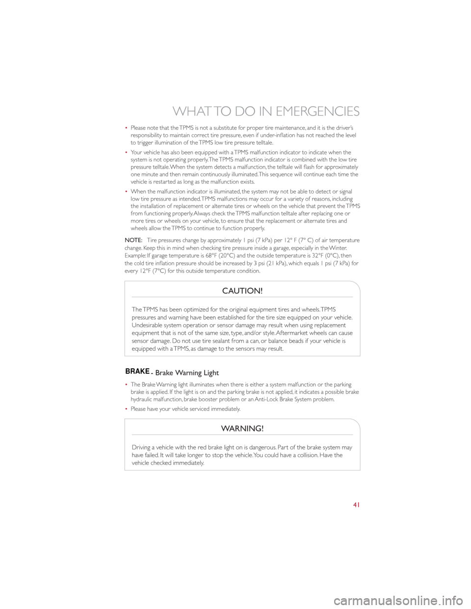
BRAKE- Brake Warning Light
• The Brake Warning light illuminates when there is either a system malfunction or the parking
brake is applied. If the light is on and the parking brake is not applied, it indicates a possible brake
hydraulic malfunction, brake booster problem or an Anti-Lock Brake System problem.
• Please have your vehicle serviced immediately.
WARNING!
Driving a vehicle with the red brake light on is dangerous. Part of the brake system may
have failed. It will take longer to stop the vehicle.You could have a collision. Have the
vehicle checked immediately.
WHAT TO DO IN EMERGENCIES
41
Page 67 of 80

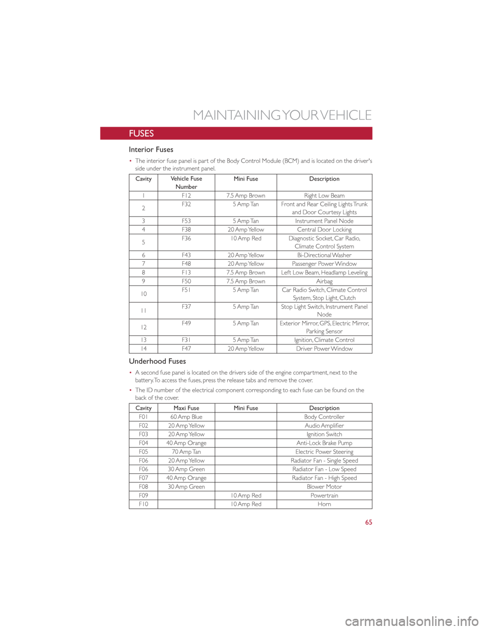
FUSES
Interior Fuses
•The interior fuse panel is part of the Body Control Module (BCM) and is located on the driver's
side under the instrument panel.
Cavity Vehicle Fuse
Number Mini Fuse
Description
1 F12 7.5 Amp Brown Right Low Beam
2 F32
5 Amp Tan Front and Rear Ceiling Lights Trunk
and Door Courtesy Lights
3 F53 5 Amp Tan Instrument Panel Node
4 F38 20 Amp Yellow Central Door Locking
5 F36
10 Amp Red Diagnostic Socket, Car Radio,
Climate Control System
6 F43 20 Amp Yellow Bi-Directional Washer
7 F48 20 Amp Yellow Passenger Power Window
8 F13 7.5 Amp Brown Left Low Beam, Headlamp Leveling
9 F50 7.5 Amp Brown Airbag
10 F51
5 Amp Tan Car Radio Switch, Climate Control
System, Stop Light, Clutch
11 F37
5 Amp Tan Stop Light Switch, Instrument Panel
Node
12 F49
5 Amp Tan Exterior Mirror, GPS, Electric Mirror,
Parking Sensor
13 F31 5 Amp Tan Ignition, Climate Control
14 F47 20 Amp Yellow Driver Power Window
Underhood Fuses
•A second fuse panel is located on the drivers side of the engine compartment, next to the
battery.To access the fuses, press the release tabs and remove the cover.
• The ID number of the electrical component corresponding to each fuse can be found on the
back of the cover.
Cavity Maxi Fuse Mini FuseDescription
F01 60 Amp Blue Body Controller
F02 20 Amp Yellow Audio Amplifier
F03 20 Amp Yellow Ignition Switch
F04 40 Amp Orange Anti-Lock Brake Pump
F05 70 Amp Tan Electric Power Steering
F06 20 Amp Yellow Radiator Fan - Single Speed
F06 30 Amp Green Radiator Fan - Low Speed
F07 40 Amp Orange Radiator Fan - High Speed
F08 30 Amp Green Blower Motor
F09 10 Amp RedPowertrain
F10 10 Amp RedHorn
MAINTAINING YOUR VEHICLE
65