maintenance FIAT 500C 2016 2.G Owners Manual
[x] Cancel search | Manufacturer: FIAT, Model Year: 2016, Model line: 500C, Model: FIAT 500C 2016 2.GPages: 442, PDF Size: 3.1 MB
Page 3 of 442

TABLE OF CONTENTSSECTIONPAGE
1INTRODUCTION .
..............................................................3
2THINGS TO KNOW BEFORE STARTING YOUR VEHICLE
..................................9
3UNDERSTANDING THE FEATURES OF YOUR VEHICLE
..................................81
4UNDERSTANDING YOUR INSTRUMENT PANEL
......................................133
5STARTINGANDOPERATING ....................................................221
6WHATTODOINEMERGENCIES..................................................305
7MAINTAININGYOURVEHICLE...................................................345
8MAINTENANCE SCHEDULES
....................................................405
9IF YOU NEED CONSUMER ASSISTANCE
............................................413
10INDEX .....................................................................423
1
2
3
4
5
6
7
8
9
10
Page 6 of 442

INTRODUCTION
Congratulations on selecting your new vehicle. Be as-
sured that it represents precision workmanship, distinc-
tive styling, and high quality - all essentials that are
traditional to our vehicles.
This Owner’s Manual has been prepared with the assis-
tance of service and engineering specialists to acquaint
you with the operation and maintenance of your vehicle.
It is supplemented by Warranty Information, and various
customer-oriented documents. Please take the time to
read these publications carefully. Following the instruc-
tions and recommendations in this manual will help
assure safe and enjoyable operation of your vehicle.
The enclosed Warranty Information lists the services that
FCA US LLC offers to its customers:
•The Warranty with terms and conditions for maintain-
ing its validity
• The range of additional services available to FCA US
LLC customers NOTE: After reviewing the owner information, it
should be stored in the vehicle for convenient referenc-
ing and remain with the vehicle when sold.
When it comes to service, remember that your authorized
dealer knows your vehicle best, has factory-trained tech-
nicians and genuine MOPAR® parts, and cares about
your satisfaction.
HOW TO USE THIS MANUAL
Consult the Table of Contents to determine which section
contains the information you desire.
Since the specification of your vehicle depends on the
items of equipment ordered, certain descriptions and
illustrations may differ from your vehicle’s equipment.
The detailed index at the back of this Owner’s Manual
contains a complete listing of all subjects.
Consult the following table for a description of the
symbols that may be used on your vehicle or throughout
this Owner’s Manual:
4 INTRODUCTION
Page 15 of 442
WARNING!(Continued)
•Do not leave children or animals inside parked
vehicles in hot weather. Interior heat build-up may
cause serious injury or death.
CAUTION!
An unlocked vehicle is an invitation. Always remove
the key from the ignition and lock all the doors when
leaving the vehicle unattended.
Locking Doors With A Key
You can insert the key with either side up. To lock the
door, turn the key to the left. To unlock the door, turn the
key to the right. Refer to “Body Lubrication” in “Main-
taining Your Vehicle” for maintenance procedures.
Key-In-Ignition Reminder
Opening the driver’s door when the key is in the ignition
and the ignition switch position is OFF/LOCK sounds a
signal to remove the key.
SENTRY KEY
The Sentry Key Immobilizer System prevents unauthor-
ized vehicle operation by disabling the engine. The
system does not need to be armed or activated. Operation
is automatic, regardless of whether the vehicle is locked
or unlocked.
The system uses ignition keys which have an embedded
electronic chip (transponder) to prevent unauthorized
vehicle operation. Therefore, only keys that are pro-
grammed to the vehicle can be used to start and operate
the vehicle.
2
THINGS TO KNOW BEFORE STARTING YOUR VEHICLE 13
Page 55 of 442
the MAR position. After the self-check, the Air Bag
Warning Light will turn off. If the ORC detects a mal-
function in any part of the system, it turns on the Air
Bag Warning Light, either momentarily or continuously.
A single chime will sound to alert you if the light comes
on again after initial startup.
The ORC also includes diagnostics that will illuminate
the instrument panel Air Bag Warning Light if a malfunc-
tion is detected that could affect the air bag system. The
diagnostics also record the nature of the malfunction.
While the air bag system is designed to be maintenance
free, if any of the following occurs, have an authorized
dealer service the air bag system immediately.
•The Air Bag Warning Light does not come on during
the four to eight seconds when the ignition switch is
first turned to the MAR position.
• The Air Bag Warning Light remains on after the four to
eight-second interval. •
The Air Bag Warning Light comes on intermittently or
remains on while driving.
NOTE: If the speedometer, tachometer, or any engine
related gauges are not working, the Occupant Restraint
Controller (ORC) may also be disabled. In this condition
the air bags may not be ready to inflate for your protec-
tion. Have an authorized dealer service the air bag
system immediately.
WARNING!
Ignoring the Air Bag Warning Light in your instru-
ment panel could mean you won’t have the air bags
to protect you in a collision. If the light does not come
on as a bulb check when the ignition is first turned
on, stays on after you start the vehicle, or if it comes
on as you drive, have an authorized dealer service the
air bag system immediately.
2
THINGS TO KNOW BEFORE STARTING YOUR VEHICLE 53
Page 162 of 442

IMPORTANT:Do not continue driving with one or more
flat tires as handling may be compromised. Stop the
vehicle, avoiding sharp braking and steering. Repair
immediately using the dedicated tire repair kit and
contact your authorized dealership as soon as possible.
Each tire, including the spare (if provided), should be
checked monthly when cold and inflated to the inflation
pressure recommended by the vehicle manufacturer on
the vehicle placard or tire inflation pressure label. If your
vehicle has tires of a different size than the size indicated
on the vehicle placard or tire inflation pressure label, you
should determine the proper tire inflation pressure for
those tires.
As an added safety feature, your vehicle has been
equipped with a Tire Pressure Monitoring System (TPMS)
that illuminates a low tire pressure telltale when one or
more of your tires is significantly under-inflated. Accord-
ingly, when the low tire pressure telltale illuminates, you should stop and check your tires as soon as possible and
inflate them to the proper pressure. Driving on a signifi-
cantly under-inflated tire causes the tire to overheat and
can lead to tire failure. Under-inflation also reduces fuel
efficiency and tire tread life, and may affect the vehicle’s
handling and stopping ability.
Please note that the TPMS is not a substitute for proper
tire maintenance, and it is the driver ’s responsibility to
maintain correct tire pressure, even if under-inflation has
not reached the level to trigger illumination of the TPMS
low tire pressure telltale.
Your vehicle has also been equipped with a TPMS
malfunction indicator to indicate when the system is not
operating properly. The TPMS malfunction indicator is
combined with the low tire pressure telltale. When the
system detects a malfunction, the telltale will flash for
approximately one minute and then remain continuously
160 UNDERSTANDING YOUR INSTRUMENT PANEL
Page 181 of 442

after a single chime has sounded to indicate the next
scheduled oil change interval. The engine oil change
indicator system is duty cycle based, which means the
engine oil change interval may fluctuate, dependent
upon your personal driving style.
Unless reset, this message will continue to display each
time you turn the ignition switch to the ON/RUN
position. To turn off the message temporarily, push and
release theMENUbutton. To reset the oil change indica-
tor system (after performing the scheduled maintenance),
refer to the following procedure.
1. Turn the ignition switch to the ON position. (do not start the engine.)
2. Fully push the accelerator pedal slowly, three times within 10 seconds.
3. Turn the ignition switch to the OFF/LOCK position. NOTE:
If the indicator message illuminates when you
start the vehicle, the oil change indicator system did not
reset. If necessary, repeat this procedure.
Trip Computer
The Trip Computer is located in the instrument cluster.
It features a driver-interactive display (displays informa-
tion such as trip information, range, fuel consumption,
average speed, and travel time).
Trip Button
The TRIP button, located on the right steering column
stalk, can be used to display and to reset the previously
described values.
• A short button push displays the different values.
• A long button push resets the system and then starts a
new trip.
4
UNDERSTANDING YOUR INSTRUMENT PANEL 179
Page 186 of 442
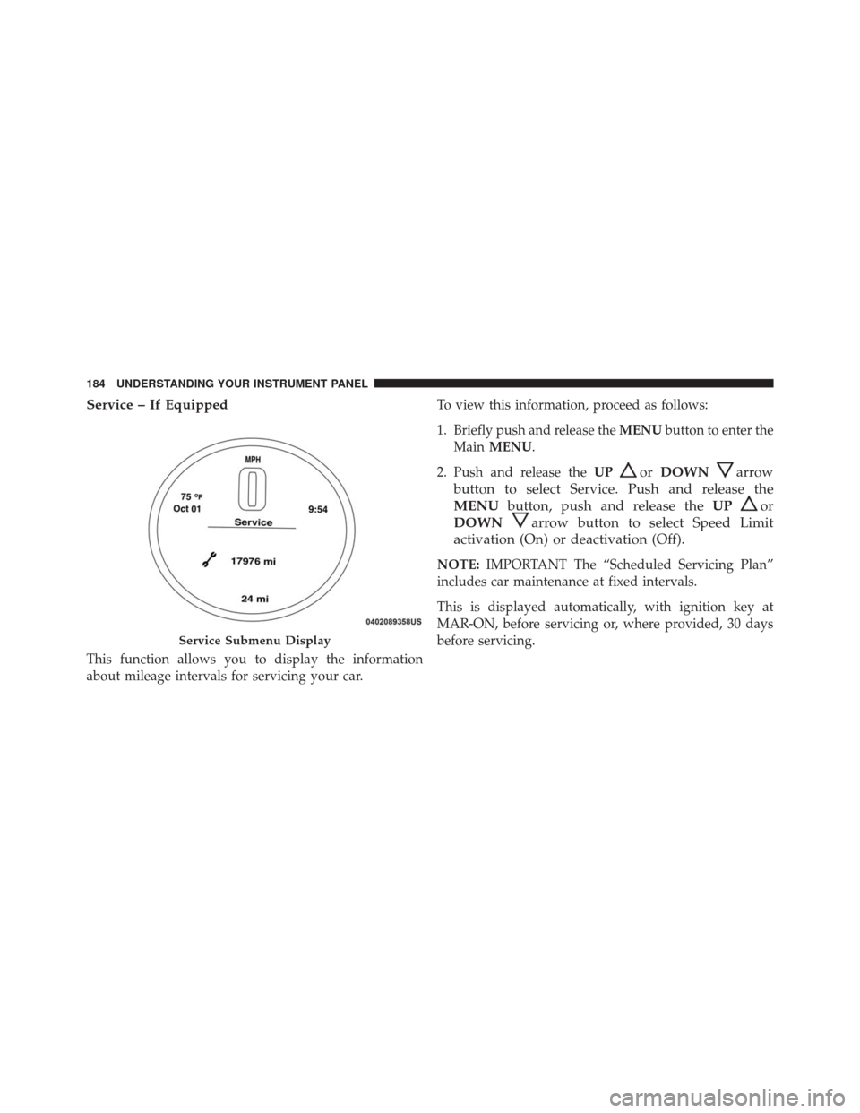
Service – If Equipped
This function allows you to display the information
about mileage intervals for servicing your car.To view this information, proceed as follows:
1. Briefly push and release the
MENUbutton to enter the
Main MENU.
2. Push and release the UP
orDOWNarrow
button to select Service. Push and release the
MENU button, push and release the UP
or
DOWN
arrow button to select Speed Limit
activation (On) or deactivation (Off).
NOTE: IMPORTANT The “Scheduled Servicing Plan”
includes car maintenance at fixed intervals.
This is displayed automatically, with ignition key at
MAR-ON, before servicing or, where provided, 30 days
before servicing.
Service Submenu Display
184 UNDERSTANDING YOUR INSTRUMENT PANEL
Page 259 of 442
WARNING!(Continued)
•Vehicle modifications, or failure to properly main-
tain your vehicle, may change the handling charac-
teristics of your vehicle, and may negatively affect
the performance of the ESC system. Changes to the
steering system, suspension, braking system, tire
type and size or wheel size may adversely affect
ESC performance. Improperly inflated and un-
evenly worn tires may also degrade ESC perfor-
mance. Any vehicle modification or poor vehicle
maintenance that reduces the effectiveness of the
ESC system can increase the risk of loss of vehicle
control, vehicle rollover, personal injury and death.
ESC Operating Modes
The ESC system has two available operating modes. Full On
This is the normal operating mode for ESC. Whenever
the vehicle is started, the ESC system will be in On mode.
This mode should be used for most driving situations.
ESC should only be turned to Partial Off for specific
reasons as noted below.
Partial Off
This mode is entered by momentarily pushing the ESC
Off switch. This mode is intended to be used if the vehicle
is in deep snow, sand or gravel conditions and more
wheel spin than ESC would normally allow is required to
gain traction.
To turn ESC on again, momentarily pushing the switch
again. This will restore the normal ESC On mode of
operation.
5
STARTING AND OPERATING 257
Page 287 of 442

TIRE ROTATION RECOMMENDATIONS
The tires on the front and rear of your vehicle operate at
different loads and perform different steering, driving,
and braking functions. For these reasons, they wear at
unequal rates.
These effects can be reduced by timely rotation of tires.
The benefits of rotation are especially worthwhile with
aggressive tread designs such as those on all season type
tires. Rotation will increase tread life, help to maintain
mud, snow and wet traction levels, and contribute to a
smooth, quiet ride.
Refer to the “Maintenance Schedule” for the proper
maintenance intervals. The reasons for any rapid or
unusual wear should be corrected prior to rotation being
performed.The suggested rotation method is the “forward cross”
shown in the following diagram. This rotation pattern
does not apply to some directional tires that must not be
reversed.
Tire Rotation
5
STARTING AND OPERATING 285
Page 290 of 442
CAUTION!(Continued)
stem, which could damage the Tire Pressure Moni-
toring Sensor.
NOTE:
• The TPMS is not intended to replace normal tire care
and maintenance, or to provide warning of a tire
failure or condition.
• The TPMS should not be used as a tire pressure gauge
while adjusting your tire pressure.
• Driving on a significantly under-inflated tire causes
the tire to overheat and can lead to tire failure.
Under-inflation also reduces fuel efficiency and tire
tread life, and may affect the vehicle’s handling and
stopping ability. •
The TPMS is not a substitute for proper tire mainte-
nance, and it is the driver ’s responsibility to maintain
correct tire pressure using an accurate tire gauge, even
if under-inflation has not reached the level to trigger
illumination of the Tire Pressure Monitoring Telltale
Light.
• Seasonal temperature changes will affect tire pressure,
and the TPMS will monitor the actual tire pressure in
the tire.
Premium TPM System With Comfort Cluster
This is the TPMS warning indicator located in the
instrument cluster.
The TPMS uses wireless technology with wheel rim
mounted electronic sensors to monitor tire pressure levels.
Sensors, mounted to each wheel as part of the valve stem,
transmit tire pressure readings to the Receiver Module.
288 STARTING AND OPERATING