FIAT 500C 2019 Owners Manual
Manufacturer: FIAT, Model Year: 2019, Model line: 500C, Model: FIAT 500C 2019Pages: 332, PDF Size: 3.17 MB
Page 201 of 332
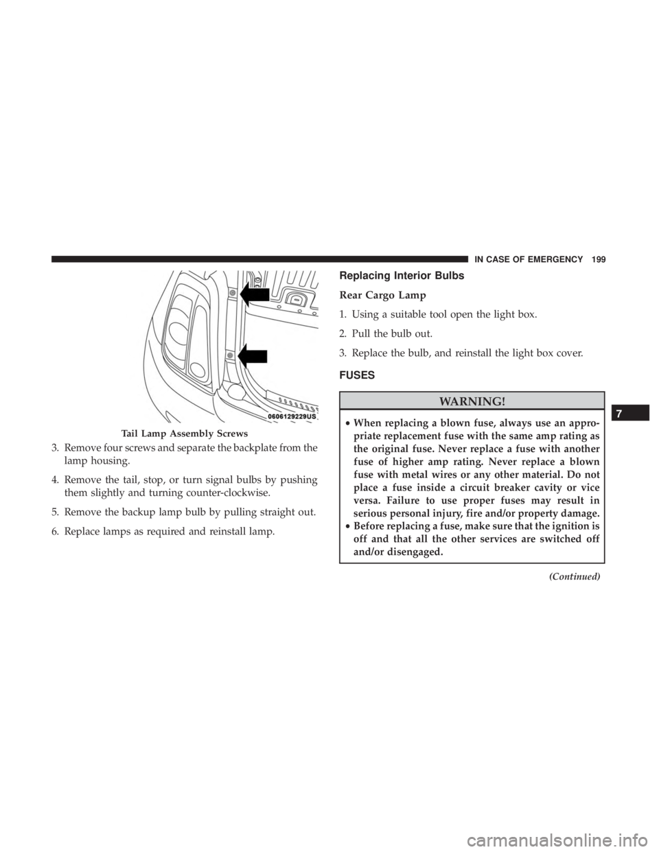
3. Remove four screws and separate the backplate from thelamp housing.
4. Remove the tail, stop, or turn signal bulbs by pushing them slightly and turning counter-clockwise.
5. Remove the backup lamp bulb by pulling straight out.
6. Replace lamps as required and reinstall lamp.
Replacing Interior Bulbs
Rear Cargo Lamp
1. Using a suitable tool open the light box.
2. Pull the bulb out.
3. Replace the bulb, and reinstall the light box cover.
FUSES
WARNING!
• When replacing a blown fuse, always use an appro-
priate replacement fuse with the same amp rating as
the original fuse. Never replace a fuse with another
fuse of higher amp rating. Never replace a blown
fuse with metal wires or any other material. Do not
place a fuse inside a circuit breaker cavity or vice
versa. Failure to use proper fuses may result in
serious personal injury, fire and/or property damage.
• Before replacing a fuse, make sure that the ignition is
off and that all the other services are switched off
and/or disengaged.
(Continued)
Tail Lamp Assembly Screws
7
IN CASE OF EMERGENCY 199
Page 202 of 332
WARNING!(Continued)
•If the replaced fuse blows again, contact an autho-
rized dealer.
• If a general protection fuse for safety systems (air
bag system, braking system), power unit systems
(engine system, transmission system) or steering
system blows, contact an authorized dealer.
Interior Fuses
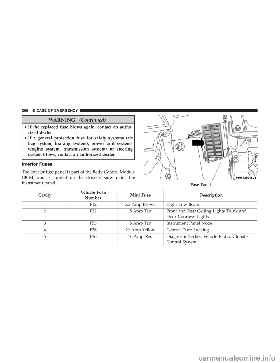
The interior fuse panel is part of the Body Control Module
(BCM) and is located on the driver’s side under the
instrument panel.
Cavity Vehicle Fuse
Number Mini Fuse
Description
1 F127.5 Amp Brown Right Low Beam
2 F325 Amp Tan Front and Rear Ceiling Lights Trunk and
Door Courtesy Lights
3 F535 Amp Tan Instrument Panel Node
4 F3820 Amp Yellow Central Door Locking
5 F3610 Amp Red Diagnostic Socket, Vehicle Radio, Climate
Control System
Fuse Panel
200 IN CASE OF EMERGENCY
Page 203 of 332
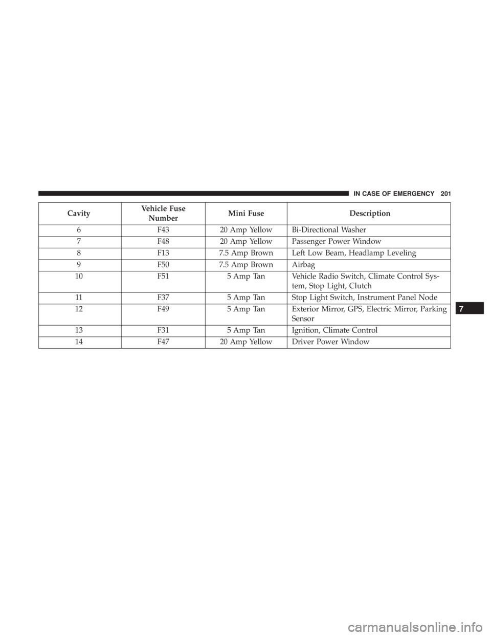
CavityVehicle Fuse
Number Mini Fuse
Description
6 F4320 Amp Yellow Bi-Directional Washer
7 F4820 Amp Yellow Passenger Power Window
8 F137.5 Amp Brown Left Low Beam, Headlamp Leveling
9 F507.5 Amp Brown Airbag
10 F515 Amp Tan Vehicle Radio Switch, Climate Control Sys-
tem, Stop Light, Clutch
11 F375 Amp Tan Stop Light Switch, Instrument Panel Node
12 F495 Amp Tan Exterior Mirror, GPS, Electric Mirror, Parking
Sensor
13 F315 Amp Tan Ignition, Climate Control
14 F4720 Amp Yellow Driver Power Window
7
IN CASE OF EMERGENCY 201
Page 204 of 332
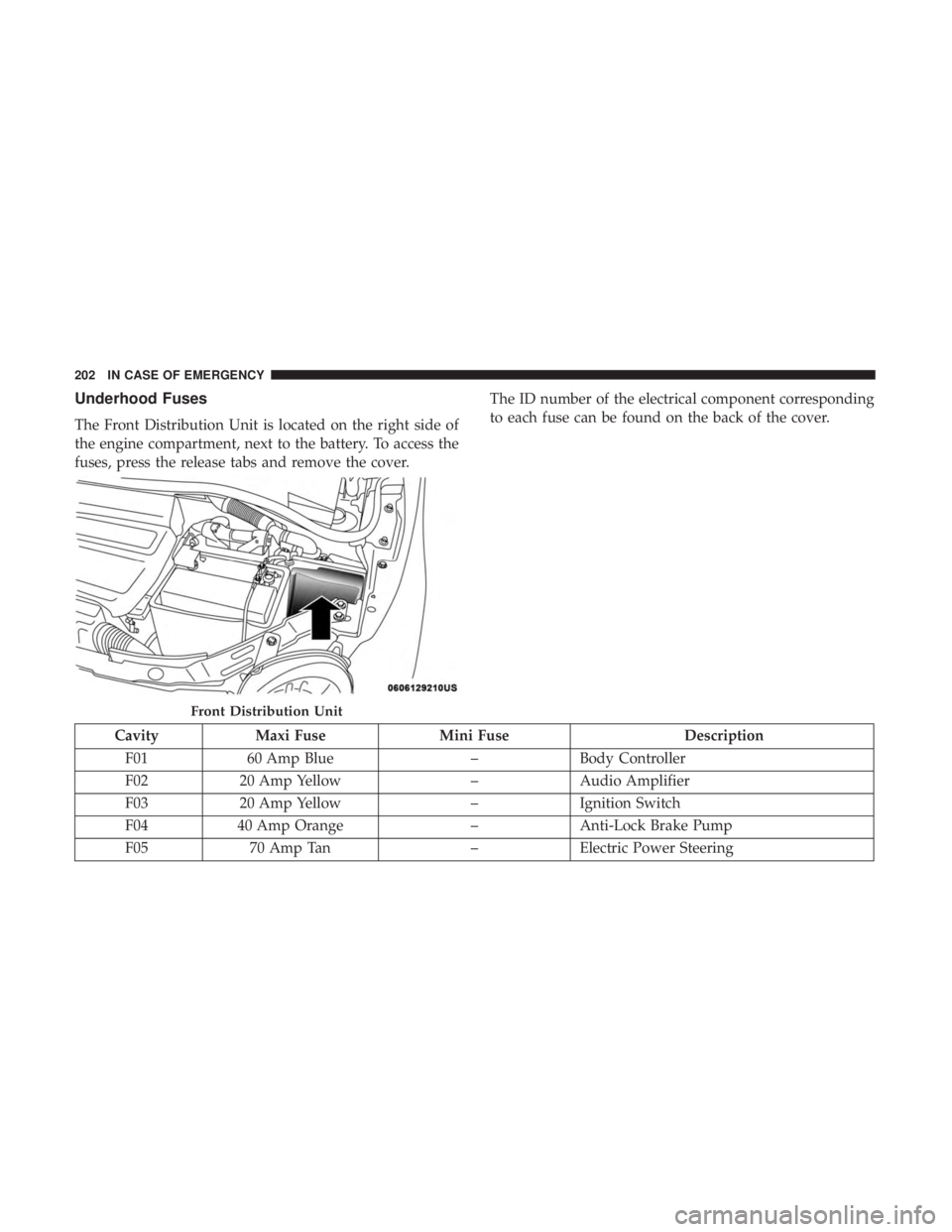
Underhood Fuses
The Front Distribution Unit is located on the right side of
the engine compartment, next to the battery. To access the
fuses, press the release tabs and remove the cover.The ID number of the electrical component corresponding
to each fuse can be found on the back of the cover.
Cavity
Maxi Fuse Mini Fuse Description
F01 60 Amp Blue –Body Controller
F02 20 Amp Yellow –Audio Amplifier
F03 20 Amp Yellow –Ignition Switch
F04 40 Amp Orange –Anti-Lock Brake Pump
F05 70 Amp Tan –Electric Power Steering
Front Distribution Unit
202 IN CASE OF EMERGENCY
Page 205 of 332
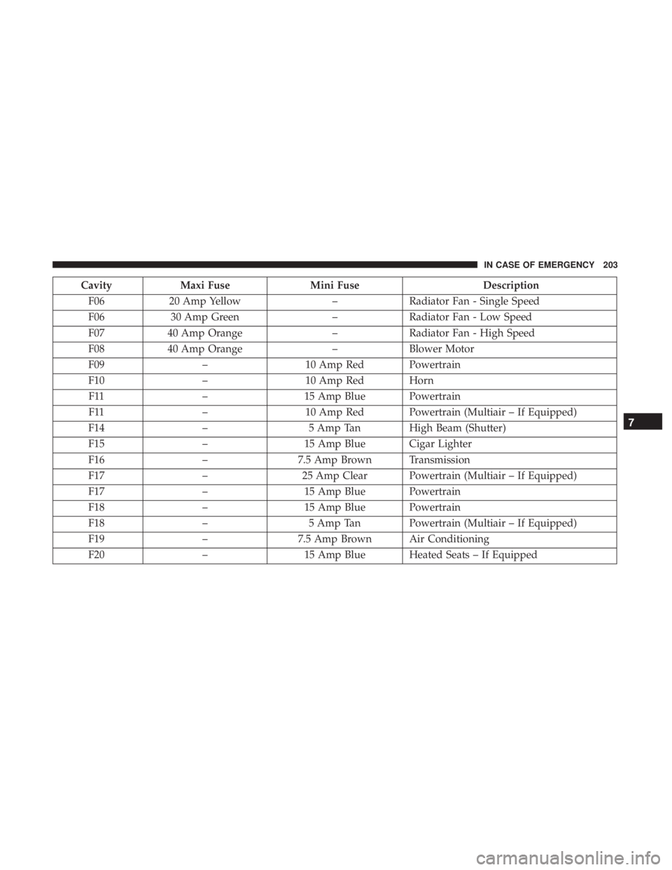
CavityMaxi Fuse Mini Fuse Description
F06 20 Amp Yellow –Radiator Fan - Single Speed
F06 30 Amp Green –Radiator Fan - Low Speed
F07 40 Amp Orange –Radiator Fan - High Speed
F08 40 Amp Orange –Blower Motor
F09 –10 Amp Red Powertrain
F10 –10 Amp Red Horn
F11 –15 Amp Blue Powertrain
F11 –10 Amp Red Powertrain (Multiair – If Equipped)
F14 –5 Amp Tan High Beam (Shutter)
F15 –15 Amp Blue Cigar Lighter
F16 –7.5 Amp Brown Transmission
F17 –25 Amp Clear Powertrain (Multiair – If Equipped)
F17 –15 Amp Blue Powertrain
F18 –15 Amp Blue Powertrain
F18 –5 Amp Tan Powertrain (Multiair – If Equipped)
F19 –7.5 Amp Brown Air Conditioning
F20 –15 Amp Blue Heated Seats – If Equipped
7
IN CASE OF EMERGENCY 203
Page 206 of 332
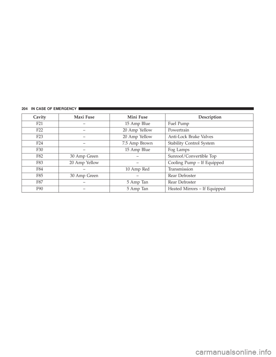
CavityMaxi Fuse Mini Fuse Description
F21 –15 Amp Blue Fuel Pump
F22 –20 Amp Yellow Powertrain
F23 –20 Amp Yellow Anti-Lock Brake Valves
F24 –7.5 Amp Brown Stability Control System
F30 –15 Amp Blue Fog Lamps
F82 30 Amp Green –Sunroof/Convertible Top
F83 20 Amp Yellow –Cooling Pump – If Equipped
F84 –10 Amp Red Transmission
F85 30 Amp Green –Rear Defroster
F87 –5 Amp Tan Rear Defroster
F90 –5 Amp Tan Heated Mirrors – If Equipped
204 IN CASE OF EMERGENCY
Page 207 of 332
TIRE SERVICE KIT — IF EQUIPPED
Small punctures up to 1/4 inch (6 mm) in the tire tread can
be sealed with Tire Service Kit. Foreign objects (e.g., screws
or nails) should not be removed from the tire. Tire Service
Kit can be used in outside temperatures down to approxi-
mately -4°F (-20°C).
This kit will provide a temporary tire seal, allowing you to
drive your vehicle up to 100 miles (160 km) with a
maximum speed of 50 mph (80 km/h).
Tire Service Kit Storage
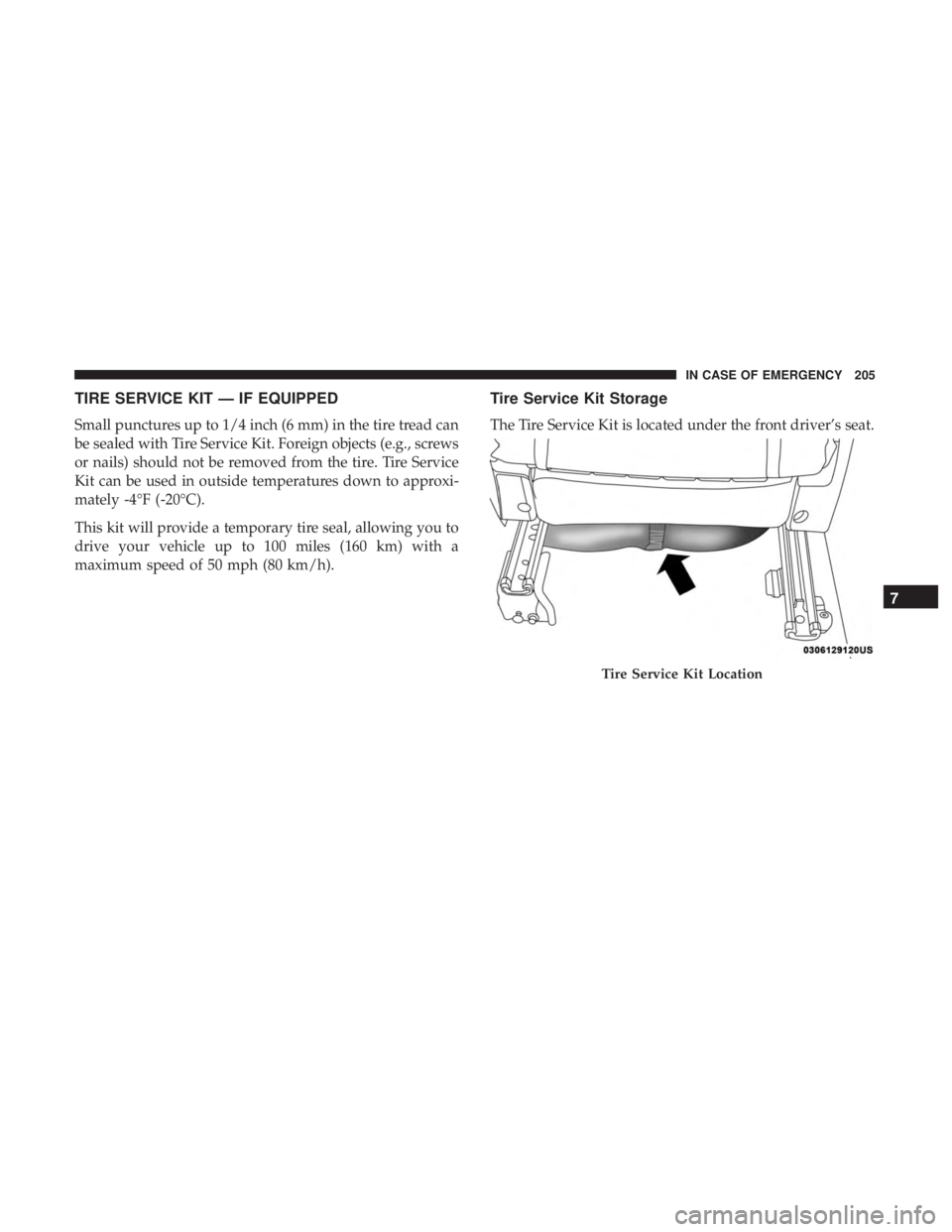
The Tire Service Kit is located under the front driver’s seat.
Tire Service Kit Location
7
IN CASE OF EMERGENCY 205
Page 208 of 332
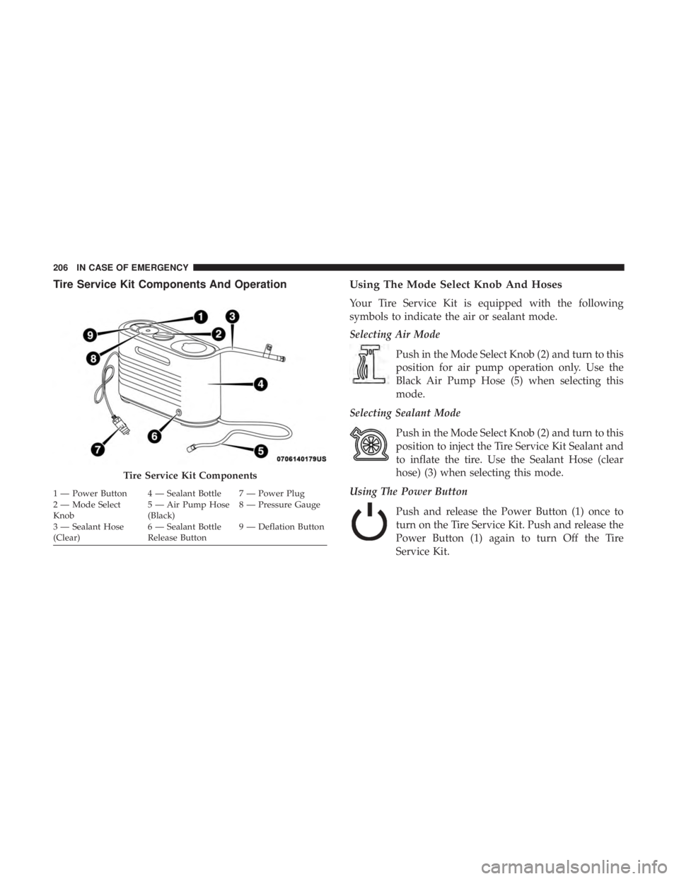
Tire Service Kit Components And OperationUsing The Mode Select Knob And Hoses
Your Tire Service Kit is equipped with the following
symbols to indicate the air or sealant mode.
Selecting Air Mode
Push in the Mode Select Knob (2) and turn to this
position for air pump operation only. Use the
Black Air Pump Hose (5) when selecting this
mode.
Selecting Sealant Mode
Push in the Mode Select Knob (2) and turn to this
position to inject the Tire Service Kit Sealant and
to inflate the tire. Use the Sealant Hose (clear
hose) (3) when selecting this mode.
Using The Power Button
Push and release the Power Button (1) once to
turn on the Tire Service Kit. Push and release the
Power Button (1) again to turn Off the Tire
Service Kit.
Tire Service Kit Components
1 — Power Button 4 — Sealant Bottle 7 — Power Plug
2 — Mode Select
Knob 5 — Air Pump Hose
(Black)8 — Pressure Gauge
3 — Sealant Hose
(Clear) 6 — Sealant Bottle
Release Button9 — Deflation Button
206 IN CASE OF EMERGENCY
Page 209 of 332
Using The Deflation ButtonPush the Deflation Button (9) to reduce the air
pressure in the tire if it becomes over-inflated.
Tire Service Kit Usage Precautions
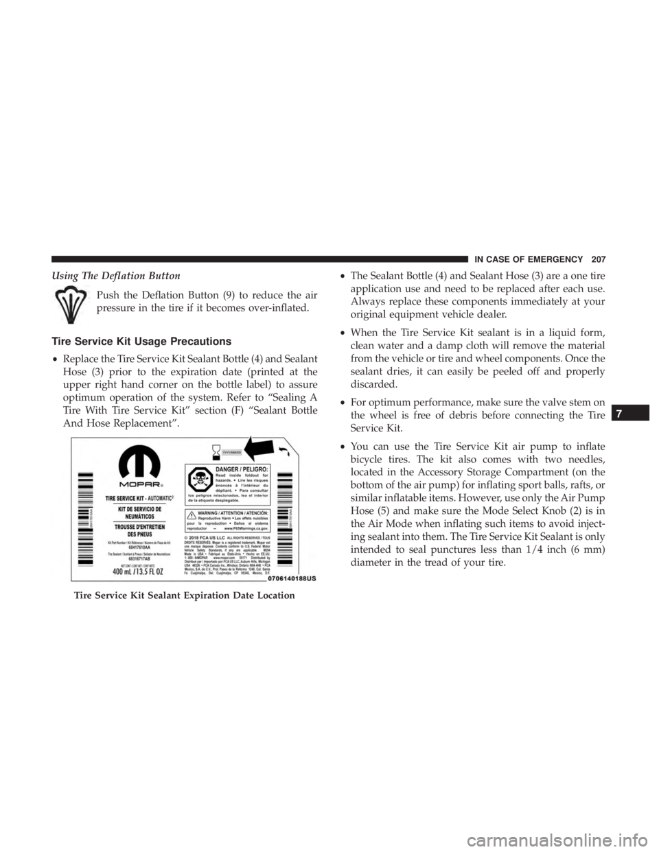
•Replace the Tire Service Kit Sealant Bottle (4) and Sealant
Hose (3) prior to the expiration date (printed at the
upper right hand corner on the bottle label) to assure
optimum operation of the system. Refer to “Sealing A
Tire With Tire Service Kit” section (F) “Sealant Bottle
And Hose Replacement”. •
The Sealant Bottle (4) and Sealant Hose (3) are a one tire
application use and need to be replaced after each use.
Always replace these components immediately at your
original equipment vehicle dealer.
• When the Tire Service Kit sealant is in a liquid form,
clean water and a damp cloth will remove the material
from the vehicle or tire and wheel components. Once the
sealant dries, it can easily be peeled off and properly
discarded.
• For optimum performance, make sure the valve stem on
the wheel is free of debris before connecting the Tire
Service Kit.
• You can use the Tire Service Kit air pump to inflate
bicycle tires. The kit also comes with two needles,
located in the Accessory Storage Compartment (on the
bottom of the air pump) for inflating sport balls, rafts, or
similar inflatable items. However, use only the Air Pump
Hose (5) and make sure the Mode Select Knob (2) is in
the Air Mode when inflating such items to avoid inject-
ing sealant into them. The Tire Service Kit Sealant is only
intended to seal punctures less than 1/4 inch (6 mm)
diameter in the tread of your tire.
Tire Service Kit Sealant Expiration Date Location
7
IN CASE OF EMERGENCY 207
Page 210 of 332
•Do not lift or carry the Tire Service Kit by the hoses.
WARNING!
•Do not attempt to seal a tire on the side of the vehicle
closest to traffic. Pull far enough off the road to avoid
the danger of being hit when using the Tire Service
Kit.
• Do not use Tire Service Kit or drive the vehicle under
the following circumstances:
– If the puncture in the tire tread is approximately 1/4 inch (6 mm) or larger.
– If the tire has any sidewall damage.
– If the tire has any damage from driving with extremely low tire pressure.
– If the tire has any damage from driving on a flat tire.
– If the wheel has any damage.
– If you are unsure of the condition of the tire or the wheel.
• Keep Tire Service Kit away from open flames or heat
source.
(Continued)
WARNING! (Continued)
•A loose Tire Service Kit thrown forward in a collision
or hard stop could endanger the occupants of the
vehicle. Always stow the Tire Service Kit in the place
provided. Failure to follow these warnings can result
in injuries that are serious or fatal to you, your
passengers, and others around you.
• Take care not to allow the contents of Tire Service Kit
to come in contact with hair, eyes, or clothing. Tire
Service Kit sealant is harmful if inhaled, swallowed,
or absorbed through the skin. It causes skin, eye, and
respiratory irritation. Flush immediately with plenty
of water if there is any contact with eyes or skin.
Change clothing as soon as possible, if there is any
contact with clothing.
• Tire Service Kit Sealant solution contains latex. In
case of an allergic reaction or rash, consult a physi-
cian immediately. Keep Tire Service Kit out of reach
of children. If swallowed, rinse mouth immediately
with plenty of water and drink plenty of water. Do
not induce vomiting! Consult a physician immedi-
ately.
208 IN CASE OF EMERGENCY