charging FIAT 500E 2014 2.G Owner's Manual
[x] Cancel search | Manufacturer: FIAT, Model Year: 2014, Model line: 500E, Model: FIAT 500E 2014 2.GPages: 92, PDF Size: 3.24 MB
Page 20 of 92
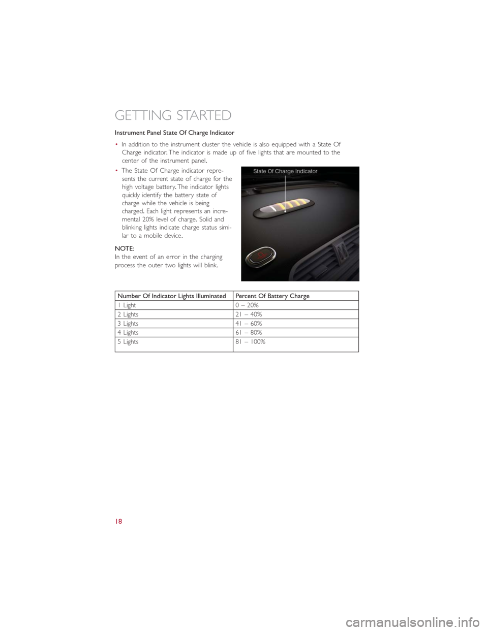
Instrument Panel State Of Charge Indicator
•In addition to the instrument cluster the vehicle is also equipped with a State Of
Charge indicator.The indicator is made up of five lights that are mounted to the
center of the instrument panel.
•The State Of Charge indicator repre-
sents the current state of charge for the
high voltage battery.The indicator lights
quickly identify the battery state of
charge while the vehicle is being
charged.Each light represents an incre-
mental 20% level of charge.Solid and
blinking lights indicate charge status simi-
lar to a mobile device.
NOTE:
In the event of an error in the charging
process the outer two lights will blink.
Number Of Indicator Lights Illuminated Percent Of Battery Charge
1 Light 0 – 20%
2 Lights 21 – 40%
3 Lights 41 – 60%
4 Lights 61 – 80%
5 Lights 81 – 100%
GETTING STARTED
18
Page 35 of 92
EXTENDING YOUR DRIVING RANGE PER CHARGE
•A little knowledge will go a long way to extend your driving range on the 500e.First
and foremost understand that the drive system and cabin temperature management
features use the most energy from the high voltage battery.Reducing energy draw
from these features are the easiest and most effective way to extend driving range.
•Just like a conventional vehicle, 500e likes to keeps things smooth and steady for most
efficient operation.When driving, avoid aggressive driving styles and high speeds for
extended times.When practical, choose surface streets over the highway, work to
maintain a steady speed to extend range.
•The 500e uses high voltage components to heat and cool the cabin, so a little aware-
ness can go a long way to extend range.When using automatic climate control, con-
sider setting temperatures a few degrees higher or lower during hot and cold days.
If your 500e has been soaking in hot or cold temperatures for an extended period, it
is recommended that the car be preconditioned via the mobile application while still
plugged into a charging source.This will allow 500e to use external power to establish
a comfortable cabin temperature before the drive, and allow the battery to maintain
the temperature using significantly less energy.
Additional Tips:
•Keep tires properly inflated
•Avoid carrying nonessential cargo
•Be mindful of adding external accessories that may increase aerodynamic drag
•Perform all scheduled maintenance at recommended intervals
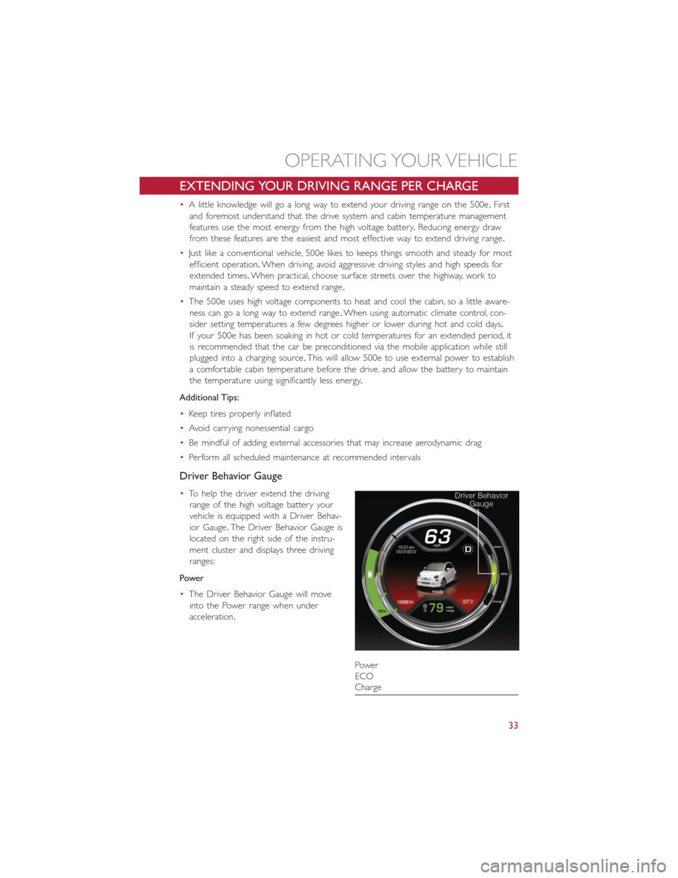
Driver Behavior Gauge
•To help the driver extend the driving
range of the high voltage battery your
vehicle is equipped with a Driver Behav-
ior Gauge.The Driver Behavior Gauge is
located on the right side of the instru-
ment cluster and displays three driving
ranges:
Power
•The Driver Behavior Gauge will move
into the Power range when under
acceleration.
Power
ECO
Charge
OPERATING YOUR VEHICLE
33
Page 54 of 92
PROGRAMMABLE FEATURES
Electronic Vehicle Information Center (EVIC)
•Push the MENU button to enter the menu mode.
•Push the UP
or DOWNbuttons to scroll through the menu settings.
•Once the menu setting is shown in the EVIC display press the MENU button to access
the setting and use the UP or DOWN buttons to change the current setting.Push the
MENU button a second time to save the setting and return to menu screen.
•Charging Schedule•Daytime Running Lights
•Set Date•Button Volume
•Set Time•Hill Start Assist
•Units•Stored Warning
•Languages•Tutorial
•Audio Display•Connectivity ID
•Battery % Display•Restore Factory Settings
•Auto Door Lock•Exit Menu
•Remote Unlock
Selecting An Option Of The Main Menu Without Submenu:
•Briefly push the MENU button to select the main menu option to set.
•Push the UP or DOWN button to select the new setting.
•Briefly press the MENU button to store the new setting and go back to the main
menu option previously selected.
Selecting An Option Of The Main Menu With Submenu:
•Briefly push the MENU button to display the first submenu option.
•Push the UP or DOWN button to scroll through all the submenu options.
•Briefly press the MENU button to select the displayed submenu option and to open
the relevant setup menu.
•Push the UP or DOWN button to select the new setting for this submenu option.
•Briefly press the MENU button to store the new setting and go back to the previously
selected submenu option.
•Push and hold the MENU button to return to the main menu (short hold) or the
main screen (longer hold).
NOTE:
The charging schedule is based on the date and time programmed in the EVIC.
ELECTRONICS
52
Page 58 of 92
24-HOUR ROADSIDE ASSISTANCE
•If your FIAT 500e requires jump start assistance, tire service, lockout service or towing
due to a defect covered under the Basic Limited Warranty, dial toll-free
1-888-242-6342.See your Warranty booklet for further details.
•Provide your name, vehicle identification number and license plate number.
•Provide your location, including telephone number, from which you are calling.
•Briefly describe the nature of the problem and answer a few simple questions.
•You will be given the name of the service provider and an estimated time of arrival.If
you feel you are in an “unsafe situation”, please let us know.With your consent, we will
contact local police or safety authorities.
INSTRUMENT CLUSTER WARNING LIGHTS
- Service Propulsion System Warning Light
•The Service Propulsion System Warning Light will illuminate if there is a malfunction
detected with the Propulsion System.If the light comes on or remains on while driving
see your authorized dealer.
- Electric Vehicle System Warning Light
•This indicator will illuminate when there is a malfunction in the Electric Vehicle System.
If the EV malfunction light comes on while driving or charging see your authorized
dealer as soon as possible.
- Regenerative Brake System Warning Light
•If the light turns on and remains on while driving, it suggests that there is a potential
problem with the Regenerative Brake System (RBS) and the need for system service.
See your authorized dealer as soon as possible.
- Power Steering System Warning
This light is used to manage the electrical warning of the EPS (Electric Power Steering
System).When the ignition is turned to the ON/RUN position, the warning light will illu-
minate momentarily.If the warning light stays on, cycle the ignition to the OFF position
and back to ON/RUN.If the warning light stays on, contact your authorized dealer.
If the warning light switches on while driving you may not have steering assistance.
Although it will still be possible to steer the car, the effort needed to operate the steer-
ing wheel could be increased: contact an authorized dealer as soon as possible.
- Electronic Stability Control (ESC) OFF Indicator Light
This light indicates the ESC system has been turned off by the driver.
WHAT TO DO IN EMERGENCIES
56
Page 61 of 92
BRAKE- Brake Warning Light
The Brake Warning light illuminates when there is either a system malfunction or the
parking brake is applied.If the light is on and the parking brake is not applied, it indicates
a possible brake hydraulic malfunction, brake booster problem or an Anti-Lock Brake Sys-
tem problem.
Please have your vehicle serviced immediately.
WARNING!
Driving a vehicle with the red brake light on is dangerous.Part of the brake system
may have failed.It will take longer to stop the vehicle.You could have a collision.Have
the vehicle checked immediately.
- 12 Volt Charging System Light
•This light shows the status of the 12 Volt electrical charging system.If the charging
system light remains on, it means that the vehicle is experiencing a problem with the
charging system.
•We recommend you do not continue driving if the charging system light is on.Have
the vehicle serviced immediately.
- Anti-Lock Brake (ABS) Light
This light monitors the Anti-Lock Brake System (ABS).
If the light is not on during starting, stays on, or turns on while driving, we recommend
you contact the nearest authorized dealer and have the vehicle serviced immediately.
- Air Bag Warning Light
If the light is not on during starting, stays on, or turns on while driving, have the vehicle
serviced by an authorized dealer immediately.
TIREFIT KIT
•Your vehicle is equipped with a TIREFIT Kit.
•Small punctures up to 1/4” (6 mm) in the tire tread can be sealed with TIREFIT.
Foreign objects (e.g., screws or nails) should not be removed from the tire.TIREFIT
can be used in outside temperatures down to approximately -4°F (-20°C).
•This kit will provide a temporary tire seal, allowing you to drive your vehicle up to
100 miles (160 km) with a maximum speed of 55 mph (90 km/h).
WHAT TO DO IN EMERGENCIES
59
Page 68 of 92
Preparations For Jump-Start
•The battery in your vehicle is located in the underhood compartment under the
beauty cover.
1.Set the parking brake, place the transmission into PARK and turn the ignition to OFF/
LOCK.
2.Turn off the heater, radio, and all unnecessary electrical accessories.
3.If using another vehicle to jump-start the battery, park the vehicle within the jumper
cables reach, set the parking brake and make sure the ignition is OFF.
Jump-Starting Procedure
1.Connect the positive(+)end of the jumper cable to the positive(+)post of the dis-
charged vehicle.
2.Connect the opposite end of the positive(+)jumper cable to the positive(+)post of
the booster battery.
3.Connect the negative end(-)of the jumper cable to the negative(-)post of the
booster battery.
4.Connect the opposite end of the negative(-)jumper cable to a good ground (ex-
posed metal part of the discharged vehicle) away from the battery and the high volt-
age cables.
5.Start the engine in the vehicle that has the booster battery, let the engine idle a few
minutes, and then start the the vehicle with the discharged battery.
•Once the vehicle has started, remove the jumper cables in the reverse sequence:
1.Disconnect the negative(-)jumper cable from the ground(-)of the vehicle with the
discharged battery.
2.Disconnect the negative end(-)of the jumper cable from the negative(-)post of the
booster battery.
3.Disconnect the opposite end of the positive(+)jumper cable from the positive(+)
post of the booster battery.
4.Disconnect the positive(+)end of the jumper cable from the positive(+)post of the
discharged vehicle.
•If frequent jump-starting is required to start your vehicle, you should have the battery
and charging system inspected at your authorized dealer.
WHAT TO DO IN EMERGENCIES
66
Page 69 of 92
CAUTION!
•Accessories that can be plugged into the vehicle power outlets draw power from
the vehicle’s battery, even when not in use (i.e., cellular phones, etc.).Eventually, if
plugged in long enough, the vehicle’s battery will discharge sufficiently to degrade
battery life and/or prevent the engine from starting.
•Do not use a portable battery booster pack or any other booster source with a
system voltage greater than 12 Volts or damage to the battery, starter motor, alter-
nator or electrical system may occur.
•Failure to follow these procedures could result in damage to the charging system
of the booster vehicle or the discharged vehicle.
WARNING!
•Do not attempt jump-starting if the battery is frozen.It could rupture or explode
and cause personal injury.
•Take care to avoid the radiator cooling fan whenever the hood is raised.It can
start anytime the ignition switch is on.You can be injured by moving fan blades.
•Remove any metal jewelry such as watch bands or bracelets that might make an
inadvertent electrical contact.You could be seriously injured.
•Batteries contain sulfuric acid that can burn your skin or eyes and generate hydro-
gen gas which is flammable and explosive.Keep open flames or sparks away from
the battery.
•Do not allow vehicles to touch each other as this could establish a ground con-
nection and personal injury could result.
•Failure to follow this procedure could result in personal injury or property damage
due to battery explosion.
•
Do not connect the cable to the negative post (-)
of the discharged battery.The resulting electrical spark could cause the battery to
explode and could result in personal injury.
WHAT TO DO IN EMERGENCIES
67
Page 81 of 92
Power Distribution Center (PDC) #2
•The Power Distribution Center #2 is located next to the battery in the underhood
compartment.To access the fuses, pull the release tabs and remove the cover.
Cavity Maxi Fuse Mini Fuse Description
FPT9 15 Amp Blue Battery Pack Control Module
(BPCM)
Power Inverter Module (PIM)
FPT13 10 Amp Red EAC (AC Compressor)
On Board Charging Module
(OBCM)
FPT16 5 Amp Tan Intelligent Battery Sensor (IBS)
FPT17 10 Amp Red EAC (AC Compressor)
Radiator Fan
FPT20 10 Amp Red Electronic Vehicle Control Unit
(EVCU)
Cavity Cartridge Fuse Description
FPT3 20 Amp Clear Battery Coolant Pump
FPT5 20 Amp Yellow Inverter Coolant Pump
TIRE PRESSURES
•Check the inflation pressure of each tire, including the spare tire, at least monthly and
inflate to the recommended pressure for your vehicle.
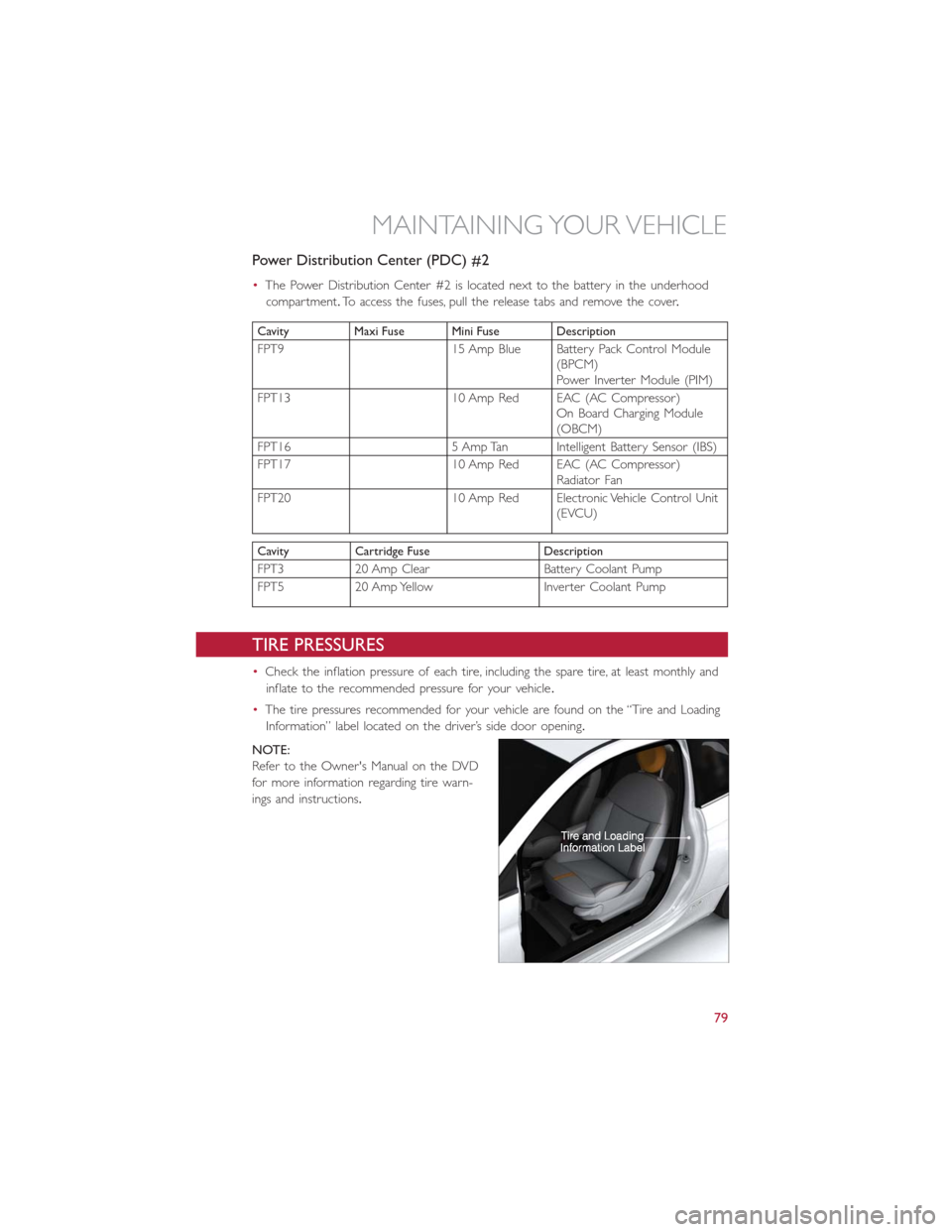
•The tire pressures recommended for your vehicle are found on the “Tire and Loading
Information” label located on the driver’s side door opening.
NOTE:
Refer to the Owner's Manual on the DVD
for more information regarding tire warn-
ings and instructions.
MAINTAINING YOUR VEHICLE
79
Page 88 of 92
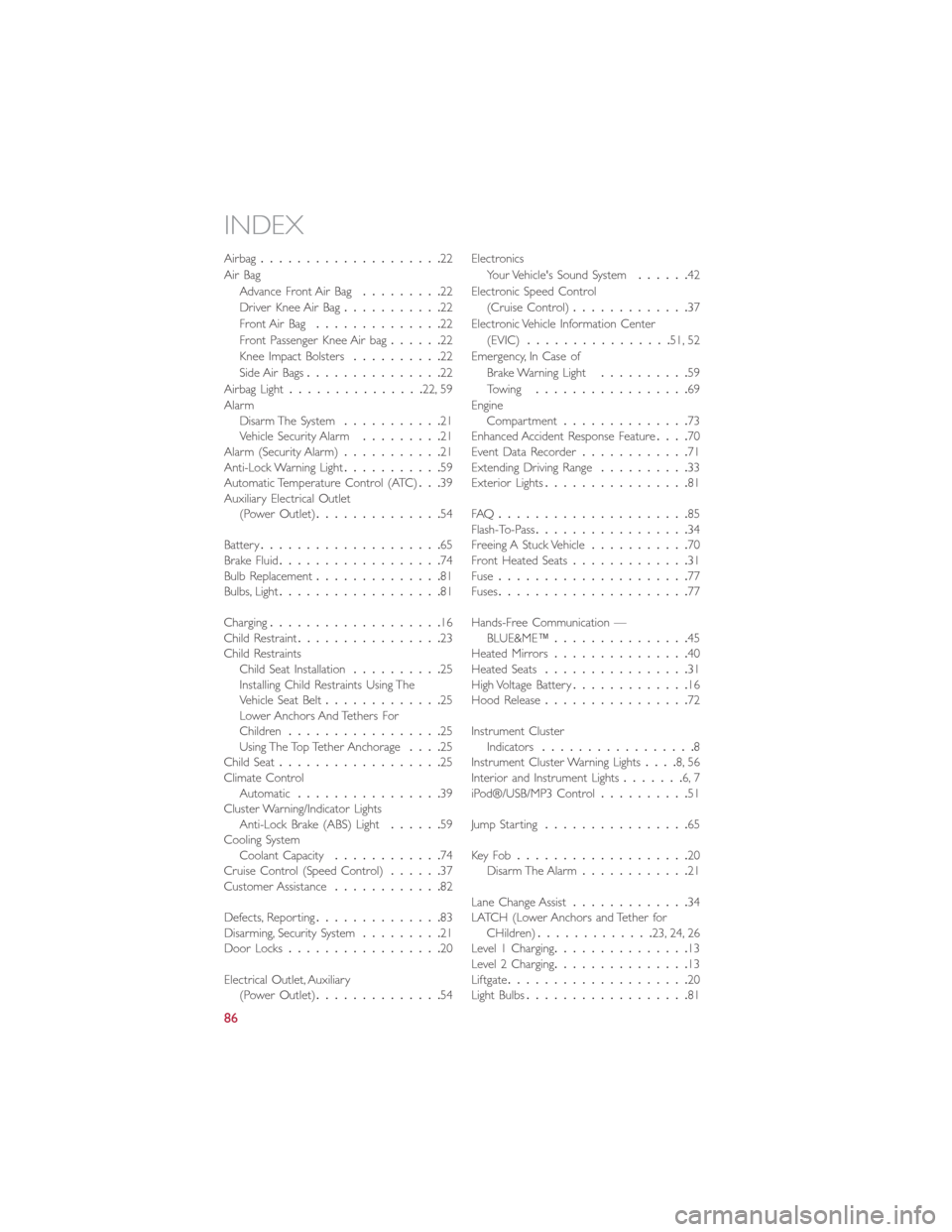
Airbag....................22
Air Bag
Advance Front Air Bag.........22
Driver Knee Air Bag...........22
Front Air Bag..............22
Front Passenger Knee Air bag......22
Knee Impact Bolsters..........22
Side Air Bags...............22
Airbag Light...............22, 59
Alarm
Disarm The System...........21
Vehicle Security Alarm.........21
Alarm (Security Alarm)...........21
Anti-Lock Warning Light...........59
Automatic Temperature Control (ATC)...39
Auxiliary Electrical Outlet
(Power Outlet)..............54
Battery....................65
Brake Fluid..................74
Bulb Replacement..............81
Bulbs, Light..................81
Charging...................16
Child Restraint................23
Child Restraints
Child Seat Installation..........25
Installing Child Restraints Using The
Vehicle Seat Belt.............25
Lower Anchors And Tethers For
Children.................25
Using The Top Tether Anchorage....25
Child Seat..................25
Climate Control
Automatic................39
Cluster Warning/Indicator Lights
Anti-Lock Brake (ABS) Light......59
Cooling System
Coolant Capacity............74
Cruise Control (Speed Control)......37
Customer Assistance............82
Defects, Reporting..............83
Disarming, Security System
.........21
Door Locks.................20
Electrical Outlet, Auxiliary
(Power Outlet)..............54Electronics
Your Vehicle's Sound System......42
Electronic Speed Control
(Cruise Control).............37
Electronic Vehicle Information Center
(EVIC)................51, 52
Emergency, In Case of
Brake Warning Light..........59
Towing.................69
Engine
Compartment..............73
Enhanced Accident Response Feature....70
Event Data Recorder............71
Extending Driving Range..........33
Exterior Lights................81
FAQ.....................85
Flash-To-Pass.................34
Freeing A Stuck Vehicle...........70
Front Heated Seats.............31
Fuse.....................77
Fuses.....................77
Hands-Free Communication —
BLUE&ME™...............45
Heated Mirrors...............40
Heated Seats................31
High Voltage Battery.............16
Hood Release................72
Instrument Cluster
Indicators.................8
Instrument Cluster Warning Lights....8, 56
Interior and Instrument Lights.......6, 7
iPod®/USB/MP3 Control..........51
Jump Starting................65
Key Fo b...................20
Disarm The Alarm............21
Lane Change Assist
.............34
LATCH (Lower Anchors and Tether for
CHildren).............23, 24, 26
Level 1 Charging...............13
Level 2 Charging...............13
Liftgate....................20
Light Bulbs..................81
INDEX
86