light FIAT 500E 2014 2.G Owner's Manual
[x] Cancel search | Manufacturer: FIAT, Model Year: 2014, Model line: 500E, Model: FIAT 500E 2014 2.GPages: 92, PDF Size: 3.24 MB
Page 43 of 92
Sun Shade
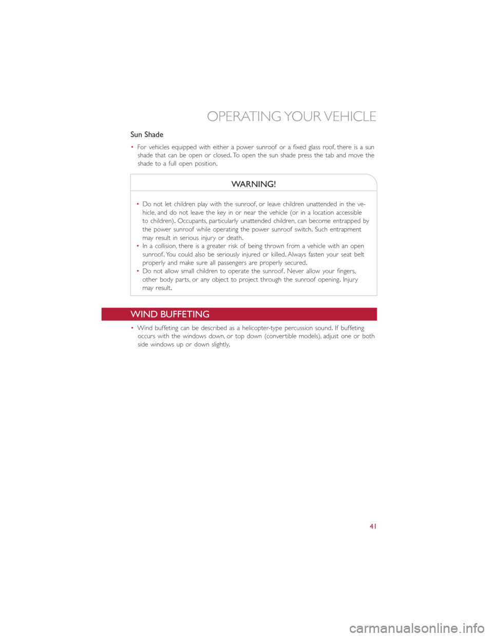
•For vehicles equipped with either a power sunroof or a fixed glass roof, there is a sun
shade that can be open or closed.To open the sun shade press the tab and move the
shade to a full open position.
WARNING!
•Do not let children play with the sunroof, or leave children unattended in the ve-
hicle, and do not leave the key in or near the vehicle (or in a location accessible
to children).Occupants, particularly unattended children, can become entrapped by
the power sunroof while operating the power sunroof switch.Such entrapment
may result in serious injury or death.
•In a collision, there is a greater risk of being thrown from a vehicle with an open
sunroof.You could also be seriously injured or killed.Always fasten your seat belt
properly and make sure all passengers are properly secured.
•Do not allow small children to operate the sunroof.Never allow your fingers,
other body parts, or any object to project through the sunroof opening.Injury
may result.
WIND BUFFETING
•Wind buffeting can be described as a helicopter-type percussion sound.If buffeting
occurs with the windows down, or top down (convertible models), adjust one or both
side windows up or down slightly.
OPERATING YOUR VEHICLE
41
Page 54 of 92
PROGRAMMABLE FEATURES
Electronic Vehicle Information Center (EVIC)
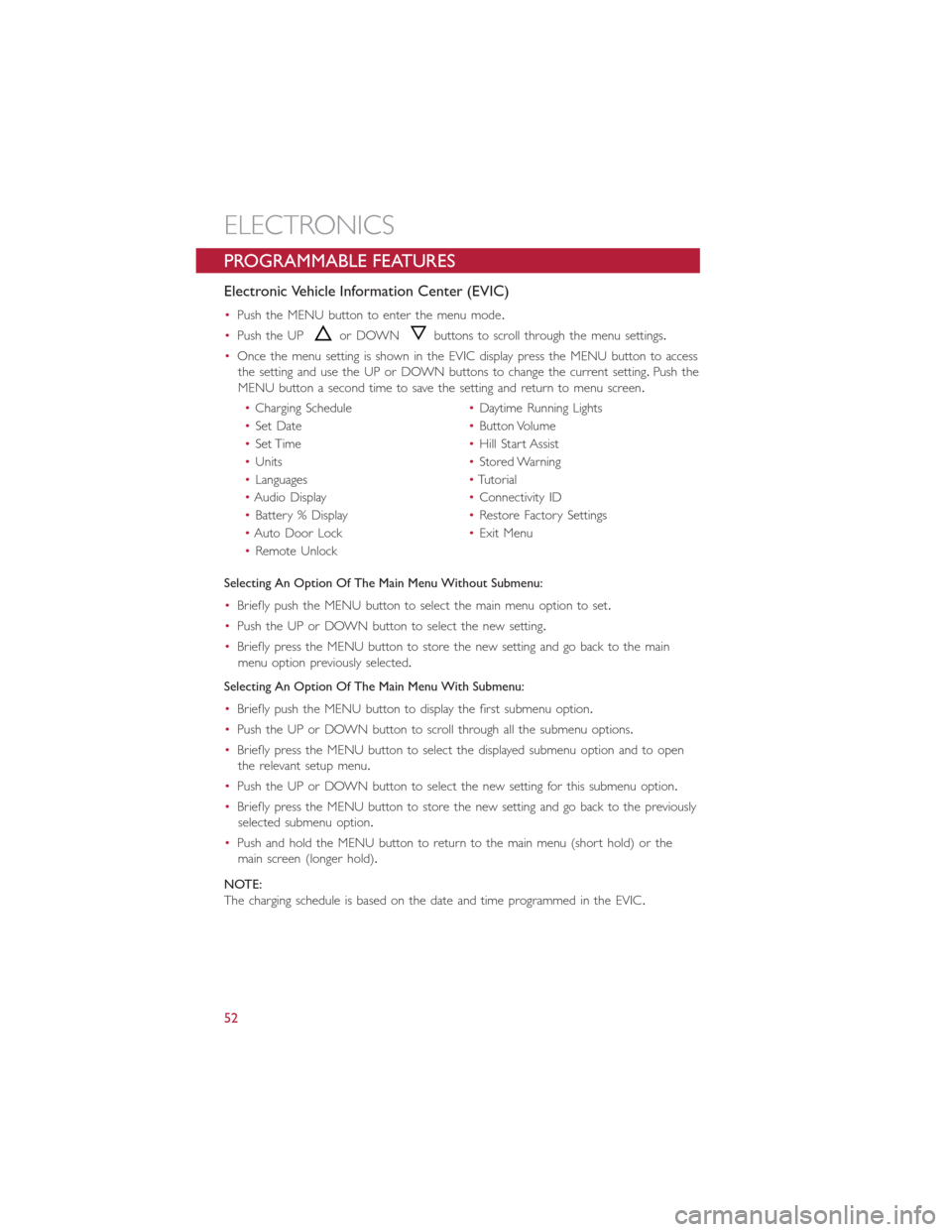
•Push the MENU button to enter the menu mode.
•Push the UP
or DOWNbuttons to scroll through the menu settings.
•Once the menu setting is shown in the EVIC display press the MENU button to access
the setting and use the UP or DOWN buttons to change the current setting.Push the
MENU button a second time to save the setting and return to menu screen.
•Charging Schedule•Daytime Running Lights
•Set Date•Button Volume
•Set Time•Hill Start Assist
•Units•Stored Warning
•Languages•Tutorial
•Audio Display•Connectivity ID
•Battery % Display•Restore Factory Settings
•Auto Door Lock•Exit Menu
•Remote Unlock
Selecting An Option Of The Main Menu Without Submenu:
•Briefly push the MENU button to select the main menu option to set.
•Push the UP or DOWN button to select the new setting.
•Briefly press the MENU button to store the new setting and go back to the main
menu option previously selected.
Selecting An Option Of The Main Menu With Submenu:
•Briefly push the MENU button to display the first submenu option.
•Push the UP or DOWN button to scroll through all the submenu options.
•Briefly press the MENU button to select the displayed submenu option and to open
the relevant setup menu.
•Push the UP or DOWN button to select the new setting for this submenu option.
•Briefly press the MENU button to store the new setting and go back to the previously
selected submenu option.
•Push and hold the MENU button to return to the main menu (short hold) or the
main screen (longer hold).
NOTE:
The charging schedule is based on the date and time programmed in the EVIC.
ELECTRONICS
52
Page 58 of 92
24-HOUR ROADSIDE ASSISTANCE
•If your FIAT 500e requires jump start assistance, tire service, lockout service or towing
due to a defect covered under the Basic Limited Warranty, dial toll-free
1-888-242-6342.See your Warranty booklet for further details.
•Provide your name, vehicle identification number and license plate number.
•Provide your location, including telephone number, from which you are calling.
•Briefly describe the nature of the problem and answer a few simple questions.
•You will be given the name of the service provider and an estimated time of arrival.If
you feel you are in an “unsafe situation”, please let us know.With your consent, we will
contact local police or safety authorities.
INSTRUMENT CLUSTER WARNING LIGHTS
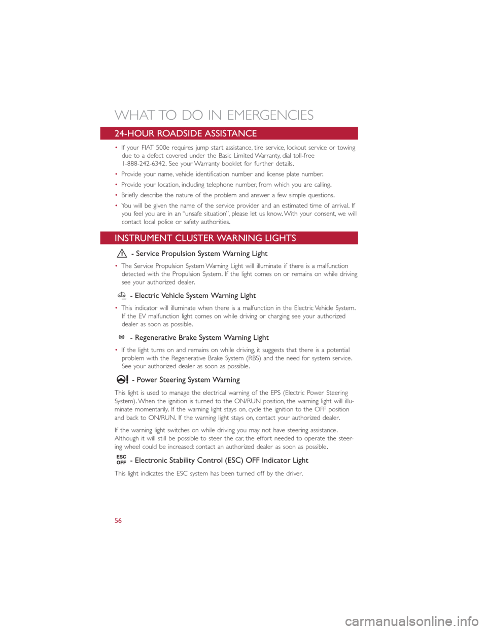
- Service Propulsion System Warning Light
•The Service Propulsion System Warning Light will illuminate if there is a malfunction
detected with the Propulsion System.If the light comes on or remains on while driving
see your authorized dealer.
- Electric Vehicle System Warning Light
•This indicator will illuminate when there is a malfunction in the Electric Vehicle System.
If the EV malfunction light comes on while driving or charging see your authorized
dealer as soon as possible.
- Regenerative Brake System Warning Light
•If the light turns on and remains on while driving, it suggests that there is a potential
problem with the Regenerative Brake System (RBS) and the need for system service.
See your authorized dealer as soon as possible.
- Power Steering System Warning
This light is used to manage the electrical warning of the EPS (Electric Power Steering
System).When the ignition is turned to the ON/RUN position, the warning light will illu-
minate momentarily.If the warning light stays on, cycle the ignition to the OFF position
and back to ON/RUN.If the warning light stays on, contact your authorized dealer.
If the warning light switches on while driving you may not have steering assistance.
Although it will still be possible to steer the car, the effort needed to operate the steer-
ing wheel could be increased: contact an authorized dealer as soon as possible.
- Electronic Stability Control (ESC) OFF Indicator Light
This light indicates the ESC system has been turned off by the driver.
WHAT TO DO IN EMERGENCIES
56
Page 59 of 92
Partial Off
This mode is entered by momentarily pressing the ESC Off switch.This mode is intended
for times when a more spirited driving experience is desired.It is also intended for driv-
ing in deep snow, sand or gravel conditions, when more wheel spin than ESC would nor-
mally allow is required to gain traction.To turn ESC on again, momentarily press the
switch again.This will restore the normal ESC On mode of operation.
Full Off
This mode is intended for off-highway or off-road use only and should not be used on
public roadways.In this mode, all TCS and ESC stability features are turned OFF, except
for the limited slip feature described in the TCS section.To enter the “Full Off ” mode,
depress and hold the ESC OFF switch for five seconds.After five seconds, the ESC OFF
Indicator Light will illuminate, and the “ESC OFF” message will display in the EVIC.To turn
ESC ON again, momentarily press the ESC OFF switch.
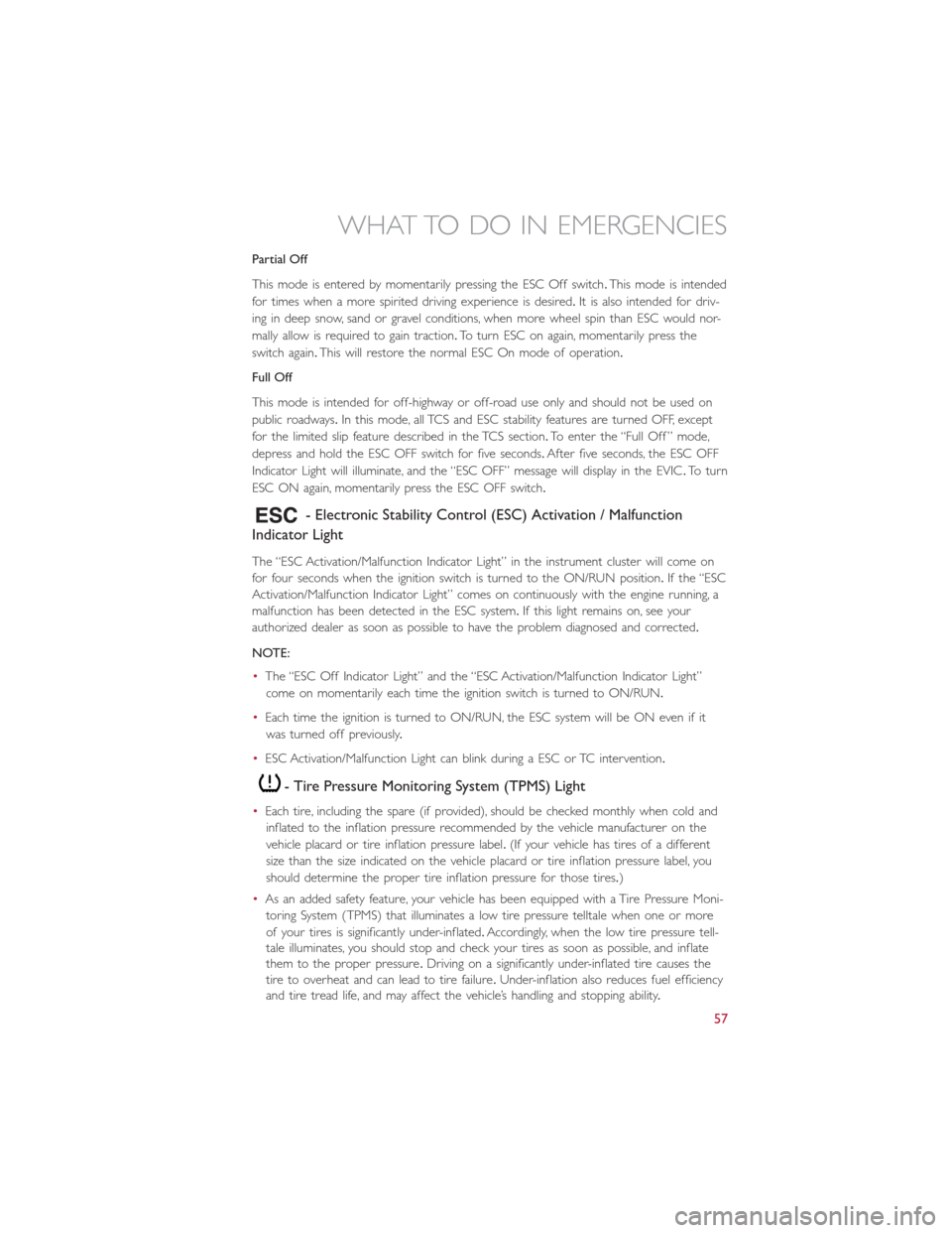
- Electronic Stability Control (ESC) Activation / Malfunction
Indicator Light
The “ESC Activation/Malfunction Indicator Light” in the instrument cluster will come on
for four seconds when the ignition switch is turned to the ON/RUN position.If the “ESC
Activation/Malfunction Indicator Light” comes on continuously with the engine running, a
malfunction has been detected in the ESC system.If this light remains on, see your
authorized dealer as soon as possible to have the problem diagnosed and corrected.
NOTE:
•The “ESC Off Indicator Light” and the “ESC Activation/Malfunction Indicator Light”
come on momentarily each time the ignition switch is turned to ON/RUN.
•Each time the ignition is turned to ON/RUN, the ESC system will be ON even if it
was turned off previously.
•ESC Activation/Malfunction Light can blink during a ESC or TC intervention.
- Tire Pressure Monitoring System (TPMS) Light
•Each tire, including the spare (if provided), should be checked monthly when cold and
inflated to the inflation pressure recommended by the vehicle manufacturer on the
vehicle placard or tire inflation pressure label.(If your vehicle has tires of a different
size than the size indicated on the vehicle placard or tire inflation pressure label, you
should determine the proper tire inflation pressure for those tires.)
•As an added safety feature, your vehicle has been equipped with a Tire Pressure Moni-
toring System (TPMS) that illuminates a low tire pressure telltale when one or more
of your tires is significantly under-inflated.Accordingly, when the low tire pressure tell-
tale illuminates, you should stop and check your tires as soon as possible, and inflate
them to the proper pressure.Driving on a significantly under-inflated tire causes the
tire to overheat and can lead to tire failure.Under-inflation also reduces fuel efficiency
and tire tread life, and may affect the vehicle’s handling and stopping ability.
WHAT TO DO IN EMERGENCIES
57
Page 60 of 92
•IF THE LIGHT STARTS FLASHING INDICATING A LOW TIRE PRESSURE, ADJUST
THE AIR PRESSURE IN THE LOW TIRE TO THE AIR PRESSURE SHOWN ON THE
VEHICLE PLACARD OR TIRE INFLATION PRESSURE LABEL LOCATED ON THE
DRIVER'S DOOR.
NOTE:
After inflation, the vehicle may need to be driven for 20 minutes before the flashing light
will turn off.
•Please note that the TPMS is not a substitute for proper tire maintenance, and it is the
driver’s responsibility to maintain correct tire pressure, even if under-inflation has not
reached the level to trigger illumination of the TPMS low tire pressure telltale.
•Your vehicle has also been equipped with a TPMS malfunction indicator to indicate
when the system is not operating properly.The TPMS malfunction indicator is com-
bined with the low tire pressure telltale.When the system detects a malfunction, the
telltale will flash for approximately one minute and then remain continuously illumi-
nated.This sequence will continue upon subsequent vehicle start-ups as long as the
malfunction exists.
•When the malfunction indicator is illuminated, the system may not be able to detect
or signal low tire pressure as intended.TPMS malfunctions may occur for a variety of
reasons, including the installation of replacement or alternate tires or wheels on the
vehicle that prevent the TPMS from functioning properly.Always check the TPMS mal-
function telltale after replacing one or more tires or wheels on your vehicle, to ensure
that the replacement or alternate tires and wheels allow the TPMS to continue to
function properly.
NOTE:
Tire pressures change by approximately 1 psi (7 kPa) per 12° F (7° C) of air tempera-
ture change.Keep this in mind when checking tire pressure inside a garage, especially in
the Winter.Example: If garage temperature is 68°F (20°C) and the outside temperature
is 32°F (0°C), then the cold tire inflation pressure should be increased by 3 psi (21 kPa),
which equals 1 psi (7 kPa) for every 12°F (7°C) for this outside temperature condition.
CAUTION!
The TPMS has been optimized for the original equipment tires and wheels.TPMS pres-
sures and warning have been established for the tire size equipped on your vehicle.
Undesirable system operation or sensor damage may result when using replacement
equipment that is not of the same size, type, and/or style.Aftermarket wheels can cause
sensor damage.Do not use tire sealant from a can, or balance beads if your vehicle is
equipped with a TPMS, as damage to the sensors may result.
WHAT TO DO IN EMERGENCIES
58
Page 61 of 92
BRAKE- Brake Warning Light
The Brake Warning light illuminates when there is either a system malfunction or the
parking brake is applied.If the light is on and the parking brake is not applied, it indicates
a possible brake hydraulic malfunction, brake booster problem or an Anti-Lock Brake Sys-
tem problem.
Please have your vehicle serviced immediately.
WARNING!
Driving a vehicle with the red brake light on is dangerous.Part of the brake system
may have failed.It will take longer to stop the vehicle.You could have a collision.Have
the vehicle checked immediately.
- 12 Volt Charging System Light
•This light shows the status of the 12 Volt electrical charging system.If the charging
system light remains on, it means that the vehicle is experiencing a problem with the
charging system.
•We recommend you do not continue driving if the charging system light is on.Have
the vehicle serviced immediately.
- Anti-Lock Brake (ABS) Light
This light monitors the Anti-Lock Brake System (ABS).
If the light is not on during starting, stays on, or turns on while driving, we recommend
you contact the nearest authorized dealer and have the vehicle serviced immediately.
- Air Bag Warning Light
If the light is not on during starting, stays on, or turns on while driving, have the vehicle
serviced by an authorized dealer immediately.
TIREFIT KIT
•Your vehicle is equipped with a TIREFIT Kit.
•Small punctures up to 1/4” (6 mm) in the tire tread can be sealed with TIREFIT.
Foreign objects (e.g., screws or nails) should not be removed from the tire.TIREFIT
can be used in outside temperatures down to approximately -4°F (-20°C).
•This kit will provide a temporary tire seal, allowing you to drive your vehicle up to
100 miles (160 km) with a maximum speed of 55 mph (90 km/h).
WHAT TO DO IN EMERGENCIES
59
Page 72 of 92
ENHANCED ACCIDENT RESPONSE SYSTEM
•In the event of an impact causing air bag deployment, if the communication network
and power remains intact, depending on the nature of the event, the ORC will deter-
mine whether to have the Enhanced Accident Response System perform the following
functions:
•Disable the high voltage battery.
•Place the transmission into PARK.
•Flash hazard lights as long as the 12 Volt battery has power or until the ignition key is
turned off.
•Turn on the interior lights, which remain on as long as the 12 Volt battery has power
or until the ignition key is removed.
•Unlock the doors automatically.
•In order to move your vehicle to the side of the road the transmission must be in
NEUTRAL and the 12 Volt system must be functional.To place the transmission into
NEUTRAL you must turn the ignition OFF and then back to the RUN position (cycle
the ignition) then press the NEUTRAL button.
NOTE:
The high voltage battery will remain disabled after an Enhanced Accident Response Event
and must be reset by your authorized dealership.
FREEING A STUCK VEHICLE
•If your vehicle becomes stuck in mud, sand or snow, it can often be moved using a
rocking motion.Turn the steering wheel right and left to clear the area around the
front wheels.Then shift back and forth between DRIVE and REVERSE while gently
pressing the accelerator.Use the least amount of accelerator pedal pressure that will
maintain the rocking motion, without spinning the wheels.
NOTE:
Press the “ESC Off ” switch, to place the Electronic Stability Control (ESC) system in “Par-
tial Off ” mode, before rocking the vehicle.Refer to “Electronic Brake Control” in “Start-
ing And Operating” for further information.Once the vehicle has been freed, press the
“ESC Off ” switch again to restore “ESC On” mode.
CAUTION!
•When “rocking” a stuck vehicle by shifting between DRIVE and REVERSE, do not
spin the wheels faster than 15 mph (24 km/h), or drivetrain damage may result.
•Spinning the wheels too fast may lead to transmission overheating and failure.It
can also damage the tires.Do not spin the wheels above 30 mph (48 km/h) while
in gear.
WHAT TO DO IN EMERGENCIES
70
Page 77 of 92
MAINTENANCE SCHEDULE
Once A Month Or Before A Trip:
•Check windshield washer fluid level
•Check the tire inflation pressures and look for unusual wear or damage
•Check the fluid levels of the coolant reservoirs and brake master cylinder
•Check function of all interior and exterior lights
Required Maintenance Intervals.
Refer to the maintenance schedules on the following page for the required maintenance
intervals.
At Every Service Interval:
•Rotate the tires.Rotate at the first sign of irregular wear.
The front and rear wheels are different sizes and cannot be used in place of each other,
refer to “Tire Rotation Recommendations” for further information.
•
Inspect brake pads, shoes, rotors, drums, and hoses.
•
Inspect battery cooling system protection and hoses.
•
Check and adjust hand brake.
MAINTAINING YOUR VEHICLE
75
Page 79 of 92
FUSES
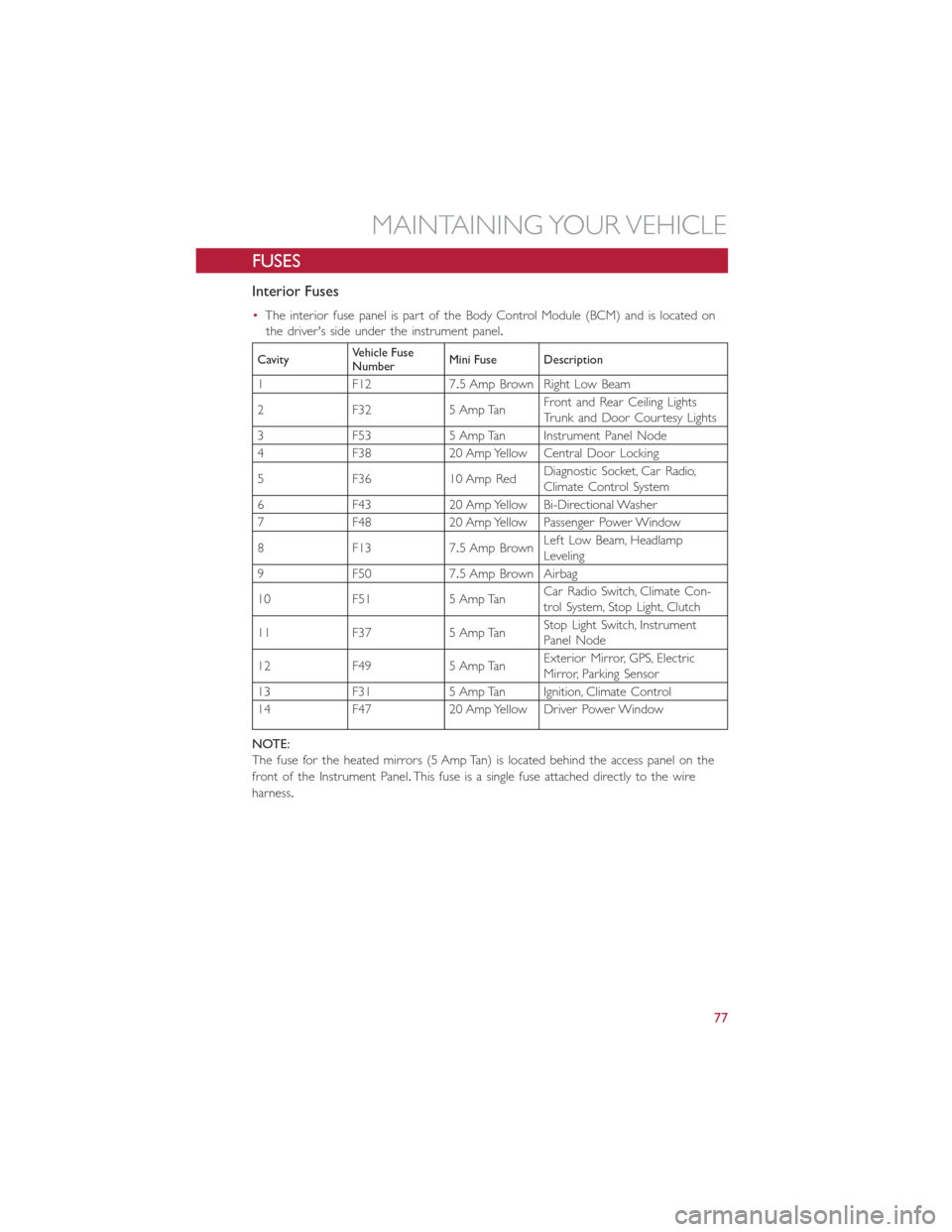
Interior Fuses
•The interior fuse panel is part of the Body Control Module (BCM) and is located on
the driver's side under the instrument panel.
CavityVehicle Fuse
NumberMini Fuse Description
1 F12 7.5 Amp Brown Right Low Beam
2 F32 5 Amp TanFront and Rear Ceiling Lights
Trunk and Door Courtesy Lights
3 F53 5 Amp Tan Instrument Panel Node
4 F38 20 Amp Yellow Central Door Locking
5 F36 10 Amp RedDiagnostic Socket, Car Radio,
Climate Control System
6 F43 20 Amp Yellow Bi-Directional Washer
7 F48 20 Amp Yellow Passenger Power Window
8 F13 7.5 Amp BrownLeft Low Beam, Headlamp
Leveling
9 F50 7.5 Amp Brown Airbag
10 F51 5 Amp TanCar Radio Switch, Climate Con-
trol System, Stop Light, Clutch
11 F37 5 Amp TanStop Light Switch, Instrument
Panel Node
12 F49 5 Amp TanExterior Mirror, GPS, Electric
Mirror, Parking Sensor
13 F31 5 Amp Tan Ignition, Climate Control
14 F47 20 Amp Yellow Driver Power Window
NOTE:
The fuse for the heated mirrors (5 Amp Tan) is located behind the access panel on the
front of the Instrument Panel.This fuse is a single fuse attached directly to the wire
harness.
MAINTAINING YOUR VEHICLE
77
Page 80 of 92
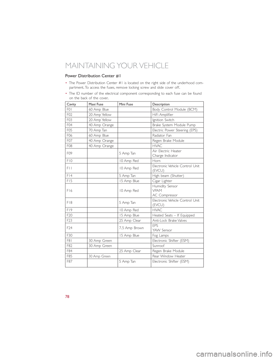
Power Distribution Center #1
•The Power Distribution Center #1 is located on the right side of the underhood com-
partment.To access the fuses, remove locking screw and slide cover off.
•The ID number of the electrical component corresponding to each fuse can be found
on the back of the cover.
Cavity Maxi Fuse Mini Fuse Description
F01 60 Amp Blue Body Control Module (BCM)
F02 20 Amp Yellow HiFi Amplifier
F03 20 Amp Yellow Ignition Switch
F04 40 Amp Orange Brake System Module Pump
F05 70 Amp Tan Electric Power Steering (EPS)
F06 60 Amp Blue Radiator Fan
F07 40 Amp Orange Regen Brake Module
F08 40 Amp Orange HVAC
F09 5 Amp TanAir Electric Heater
Charge Indicator
F10 10 Amp Red Horn
F11 10 Amp RedElectronic Vehicle Control Unit
(EVCU)
F14 5 Amp Tan High beam (Shutter)
F15 15 Amp Blue Cigar Lighter
F16 10 Amp RedHumidity Sensor
VPAM
AC Compressor
F18 5 Amp TanElectronic Vehicle Control Unit
(EVCU)
F19 10 Amp Red HVAC
F20 15 Amp Blue Heated Seats – If Equipped
F23 25 Amp Clear Anti-Lock Brake Valves
F24 7.5 Amp BrownEPS
YAW Sensor
F30 15 Amp Blue Fog Lamps
F81 30 Amp Green Electronic Shifter (ESM)
F82 30 Amp Green Sunroof
F84 25 Amp Clear Regen Brake Module
F85
30 Amp GreenRear Window Heater
F87 5 Amp Tan Electronic Shifter (ESM)
MAINTAINING YOUR VEHICLE
78