ECO mode FIAT 500E 2014 2.G User Guide
[x] Cancel search | Manufacturer: FIAT, Model Year: 2014, Model line: 500E, Model: FIAT 500E 2014 2.GPages: 92, PDF Size: 3.24 MB
Page 27 of 92
WARNING!
This vehicle does not have a center seating position.Do not use the center lower
LATCH anchorages to install a child seat in the center of the back seat.
Installing The Child Restraint Using The LATCH Lower Anchors
NOTE:
Never“share” a LATCH anchorage with two or more child restraints.
1.Loosen the adjusters on the lower straps and on the tether strap of the child seat so
that you can more easily attach the hooks or connectors to the vehicle anchorages.
2.Attach the lower hooks or connectors of the child restraint to the lower anchorages
in the selected seating position.
3.If the child restraint has a tether strap, connect it to the top tether anchorage.
See below for directions to attach a tether anchor.
4.Tighten all of the straps as you push the child restraint rearward and downward into
the seat.Remove slack in the straps according to the child restraint manufacturer’s
instructions.
5.
Test that the child restraint is installed tightly by pulling back and forth on the child seat
at the belt path.It should not move more than 1 inch (25.4 mm) in any direction.
Installing The Child Restraint Using The Vehicle Seat Belts
The seat belt in the passenger seating position are equipped with a Switchable Automatic
Locking Retractor (ALR) that is designed to keep the lap portion of the seat belt tight
around the child restraint.Any seat belt system will loosen with time, so check the belt
occasionally, and pull it tight if necessary.
Always use the tether anchor when using the seat belt to install a forward facing child
restraint, up to the recommended weight limit of the child restraint.
To Install A Child Seat Using An ALR:
1.Pull enough of the seat belt webbing from the retractor to pass it through the belt
path of the child restraint.Do not twist the belt webbing in the belt path.
2.Slide the latch plate into the buckle until you hear a “click.”
3.Pull on the webbing to make the lap portion tight against the child seat.
4.To lock the seat belt, pull down on the shoulder part of the belt until you have pulled
all the seat belt webbing out of the retractor.Then, allow the webbing to retract back
into the retractor.As the webbing retracts, you will hear a clicking sound.This means
the seat belt is now in the Automatic Locking mode.
GETTING STARTED
25
Page 43 of 92
Sun Shade
•For vehicles equipped with either a power sunroof or a fixed glass roof, there is a sun
shade that can be open or closed.To open the sun shade press the tab and move the
shade to a full open position.
WARNING!
•Do not let children play with the sunroof, or leave children unattended in the ve-
hicle, and do not leave the key in or near the vehicle (or in a location accessible
to children).Occupants, particularly unattended children, can become entrapped by
the power sunroof while operating the power sunroof switch.Such entrapment
may result in serious injury or death.
•In a collision, there is a greater risk of being thrown from a vehicle with an open
sunroof.You could also be seriously injured or killed.Always fasten your seat belt
properly and make sure all passengers are properly secured.
•Do not allow small children to operate the sunroof.Never allow your fingers,
other body parts, or any object to project through the sunroof opening.Injury
may result.
WIND BUFFETING
•Wind buffeting can be described as a helicopter-type percussion sound.If buffeting
occurs with the windows down, or top down (convertible models), adjust one or both
side windows up or down slightly.
OPERATING YOUR VEHICLE
41
Page 47 of 92
Menu
•Press the MENU button and one of the following options will appear on the Radio
display.Use the Up and Down arrows to scroll through the options; use the Left and
Right arrows to change a selection setting.
•Speech Volume•SiriusXM Telephone Number
•Aux Audio Offset•System Reset
•Radio Off•Speed Volume
•Sat ID•On Volume Limit
Station Presets
•To store a tuned station, find the station to store by either pressing the Right and Left
arrow (Seek) buttons or by pressing Up or Down arrow (Manual Tune) buttons.
•Once the station is found, press and hold one of the PRESET buttons, until you hear a
confirmation beep (Preset Saved will be shown in the radio display).A total of 15 FM,
10 AM and 15 SiriusXM Satellite Radio stations can be preset by pressing the A-B-C
button.
A-B-C Button
•Press the A-B-C button to choose between the presets stored in the AM, FM or SAT
modes.The mode (AM, FM, SAT), station preset (A, B, C) and preset button number
(P 1-5) will be displayed in the middle of the radio display.
BLUE&ME™ HANDS-FREE OPERATION
•FIAT’s Windows Mobile™ based BLUE&ME™ Hands-Free Communication is a personal
telematics system that incorporates communication and entertainment applications that
are specifically designed for use in your car.
•The BLUE&ME™ Hands-Free Communication package installed in your car is equipped
with integral hands-free functionality, message reader, and media player.BLUE&ME™ is
designed to support the future installation of additional services.
•The BLUE&ME™ Hands-Free Communication package features integrated voice recog-
nition, steering wheel controls and a multifunction electronic display that allows you to
use your Bluetooth® enabled wireless technology enabled mobile phone without
having to take your eyes off the road.You can even keep your phone in a pocket or a
bag.You are not required to train the voice recognition system to recognize your
voice.The system is “speaker independent” and performs equally well for different
users.
ELECTRONICS
45
Page 53 of 92
iPod®/USB/MP3 CONTROL
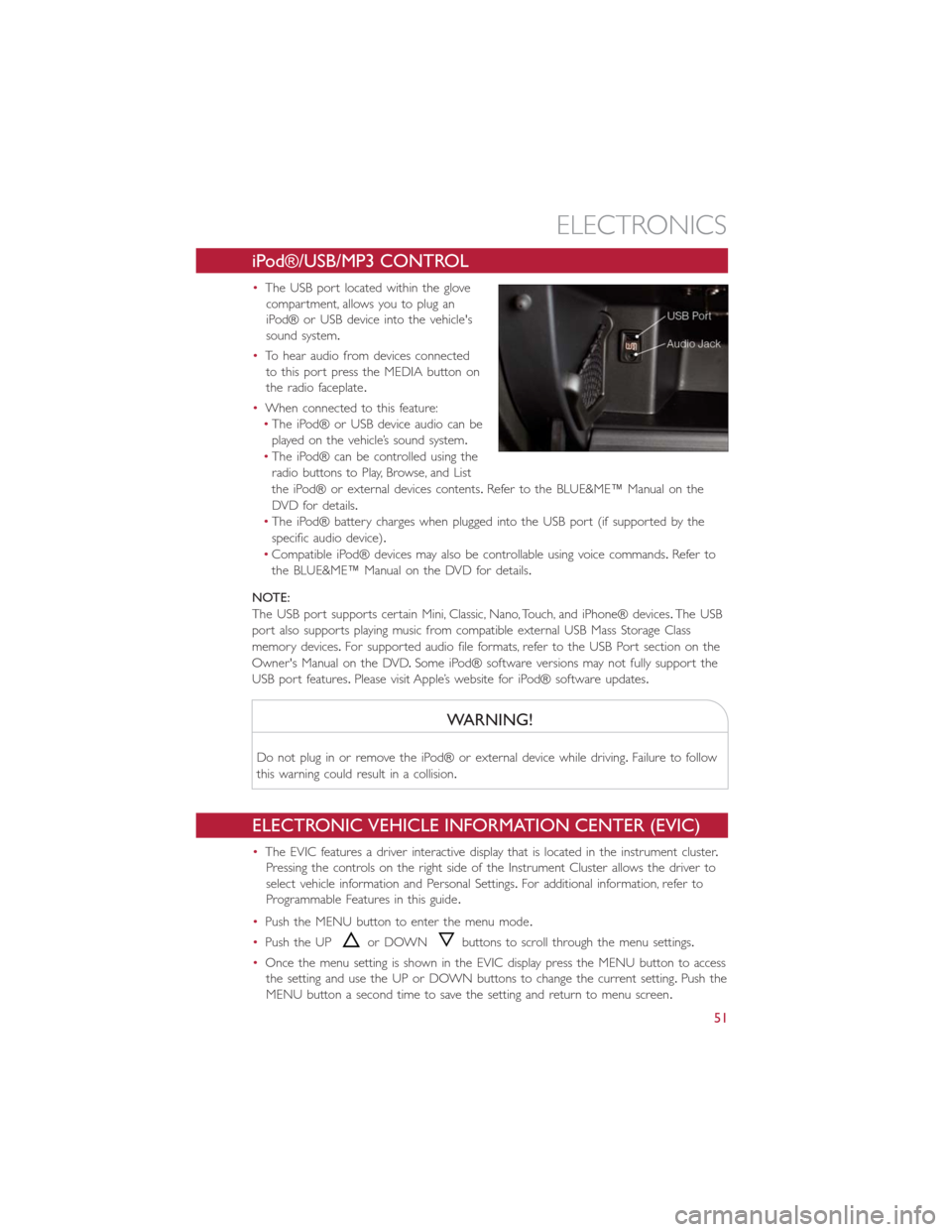
•The USB port located within the glove
compartment, allows you to plug an
iPod® or USB device into the vehicle's
sound system.
•To hear audio from devices connected
to this port press the MEDIA button on
the radio faceplate.
•When connected to this feature:
•The iPod® or USB device audio can be
played on the vehicle’s sound system.
•The iPod® can be controlled using the
radio buttons to Play, Browse, and List
the iPod® or external devices contents.Refer to the BLUE&ME™ Manual on the
DVD for details.
•The iPod® battery charges when plugged into the USB port (if supported by the
specific audio device).
•Compatible iPod® devices may also be controllable using voice commands.Refer to
the BLUE&ME™ Manual on the DVD for details.
NOTE:
The USB port supports certain Mini, Classic, Nano, Touch, and iPhone® devices.The USB
port also supports playing music from compatible external USB Mass Storage Class
memory devices.For supported audio file formats, refer to the USB Port section on the
Owner's Manual on the DVD.Some iPod® software versions may not fully support the
USB port features.Please visit Apple’s website for iPod® software updates.
WARNING!
Do not plug in or remove the iPod® or external device while driving.Failure to follow
this warning could result in a collision.
ELECTRONIC VEHICLE INFORMATION CENTER (EVIC)
•The EVIC features a driver interactive display that is located in the instrument cluster.
Pressing the controls on the right side of the Instrument Cluster allows the driver to
select vehicle information and Personal Settings.For additional information, refer to
Programmable Features in this guide.
•Push the MENU button to enter the menu mode.
•Push the UP
or DOWNbuttons to scroll through the menu settings.
•Once the menu setting is shown in the EVIC display press the MENU button to access
the setting and use the UP or DOWN buttons to change the current setting.Push the
MENU button a second time to save the setting and return to menu screen.
ELECTRONICS
51
Page 54 of 92
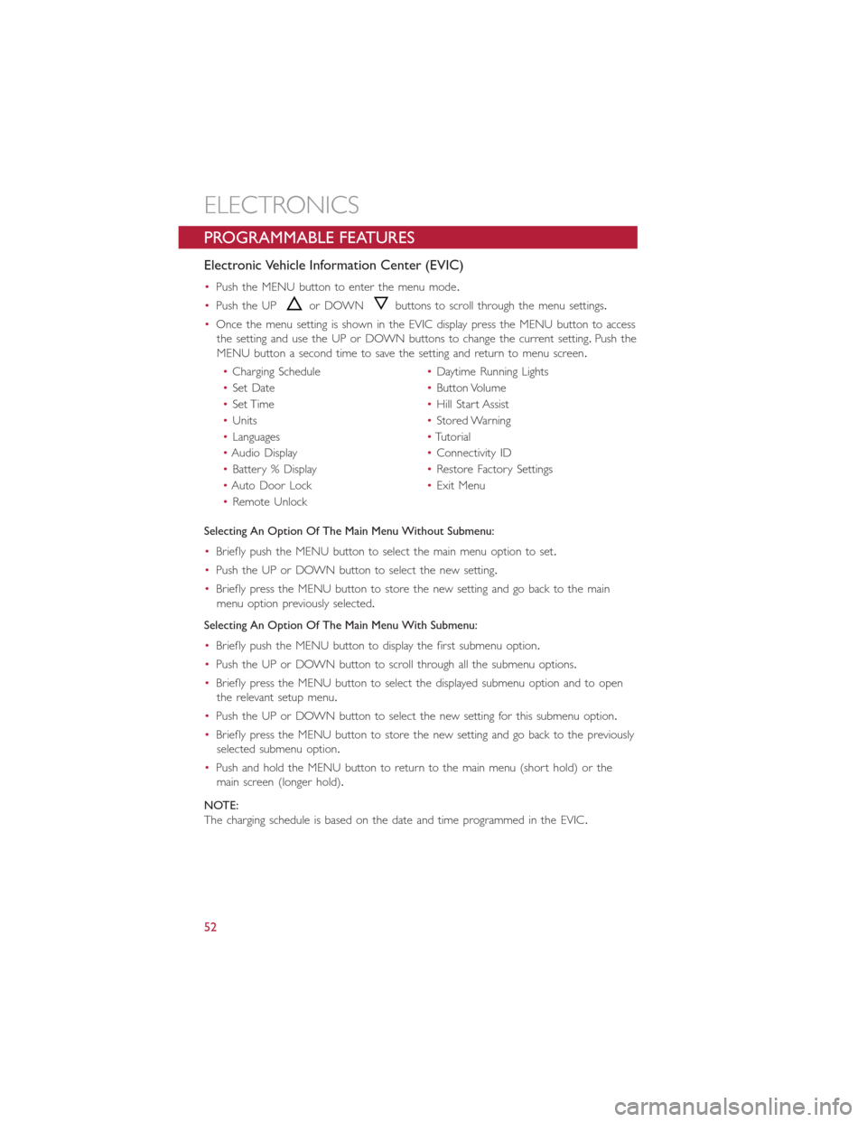
PROGRAMMABLE FEATURES
Electronic Vehicle Information Center (EVIC)
•Push the MENU button to enter the menu mode.
•Push the UP
or DOWNbuttons to scroll through the menu settings.
•Once the menu setting is shown in the EVIC display press the MENU button to access
the setting and use the UP or DOWN buttons to change the current setting.Push the
MENU button a second time to save the setting and return to menu screen.
•Charging Schedule•Daytime Running Lights
•Set Date•Button Volume
•Set Time•Hill Start Assist
•Units•Stored Warning
•Languages•Tutorial
•Audio Display•Connectivity ID
•Battery % Display•Restore Factory Settings
•Auto Door Lock•Exit Menu
•Remote Unlock
Selecting An Option Of The Main Menu Without Submenu:
•Briefly push the MENU button to select the main menu option to set.
•Push the UP or DOWN button to select the new setting.
•Briefly press the MENU button to store the new setting and go back to the main
menu option previously selected.
Selecting An Option Of The Main Menu With Submenu:
•Briefly push the MENU button to display the first submenu option.
•Push the UP or DOWN button to scroll through all the submenu options.
•Briefly press the MENU button to select the displayed submenu option and to open
the relevant setup menu.
•Push the UP or DOWN button to select the new setting for this submenu option.
•Briefly press the MENU button to store the new setting and go back to the previously
selected submenu option.
•Push and hold the MENU button to return to the main menu (short hold) or the
main screen (longer hold).
NOTE:
The charging schedule is based on the date and time programmed in the EVIC.
ELECTRONICS
52
Page 59 of 92
Partial Off
This mode is entered by momentarily pressing the ESC Off switch.This mode is intended
for times when a more spirited driving experience is desired.It is also intended for driv-
ing in deep snow, sand or gravel conditions, when more wheel spin than ESC would nor-
mally allow is required to gain traction.To turn ESC on again, momentarily press the
switch again.This will restore the normal ESC On mode of operation.
Full Off
This mode is intended for off-highway or off-road use only and should not be used on
public roadways.In this mode, all TCS and ESC stability features are turned OFF, except
for the limited slip feature described in the TCS section.To enter the “Full Off ” mode,
depress and hold the ESC OFF switch for five seconds.After five seconds, the ESC OFF
Indicator Light will illuminate, and the “ESC OFF” message will display in the EVIC.To turn
ESC ON again, momentarily press the ESC OFF switch.
- Electronic Stability Control (ESC) Activation / Malfunction
Indicator Light
The “ESC Activation/Malfunction Indicator Light” in the instrument cluster will come on
for four seconds when the ignition switch is turned to the ON/RUN position.If the “ESC
Activation/Malfunction Indicator Light” comes on continuously with the engine running, a
malfunction has been detected in the ESC system.If this light remains on, see your
authorized dealer as soon as possible to have the problem diagnosed and corrected.
NOTE:
•The “ESC Off Indicator Light” and the “ESC Activation/Malfunction Indicator Light”
come on momentarily each time the ignition switch is turned to ON/RUN.
•Each time the ignition is turned to ON/RUN, the ESC system will be ON even if it
was turned off previously.
•ESC Activation/Malfunction Light can blink during a ESC or TC intervention.
- Tire Pressure Monitoring System (TPMS) Light
•Each tire, including the spare (if provided), should be checked monthly when cold and
inflated to the inflation pressure recommended by the vehicle manufacturer on the
vehicle placard or tire inflation pressure label.(If your vehicle has tires of a different
size than the size indicated on the vehicle placard or tire inflation pressure label, you
should determine the proper tire inflation pressure for those tires.)
•As an added safety feature, your vehicle has been equipped with a Tire Pressure Moni-
toring System (TPMS) that illuminates a low tire pressure telltale when one or more
of your tires is significantly under-inflated.Accordingly, when the low tire pressure tell-
tale illuminates, you should stop and check your tires as soon as possible, and inflate
them to the proper pressure.Driving on a significantly under-inflated tire causes the
tire to overheat and can lead to tire failure.Under-inflation also reduces fuel efficiency
and tire tread life, and may affect the vehicle’s handling and stopping ability.
WHAT TO DO IN EMERGENCIES
57
Page 62 of 92
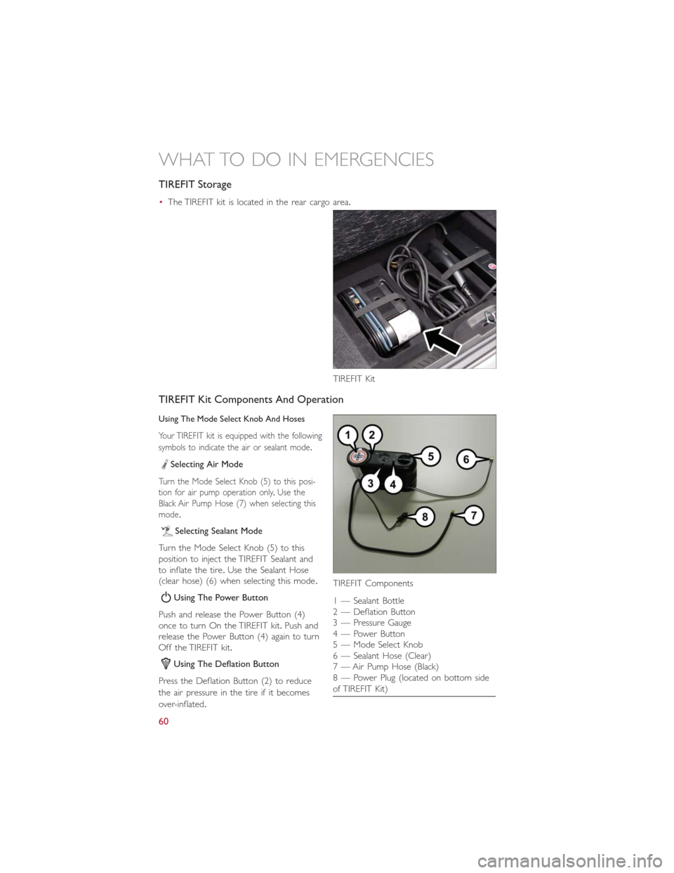
TIREFIT Storage
•The TIREFIT kit is located in the rear cargo area.
TIREFIT Kit Components And Operation
Using The Mode Select Knob And Hoses
Your TIREFIT kit is equipped with the following
symbols to indicate the air or sealant mode.
Selecting Air Mode
Turn the Mode Select Knob (5) to this posi-
tion for air pump operation only.Use the
Black Air Pump Hose (7) when selecting this
mode.
Selecting Sealant Mode
Turn the Mode Select Knob (5) to this
position to inject the TIREFIT Sealant and
to inflate the tire.Use the Sealant Hose
(clear hose) (6) when selecting this mode.
Using The Power Button
Push and release the Power Button (4)
once to turn On the TIREFIT kit.Push and
release the Power Button (4) again to turn
Off the TIREFIT kit.
Using The Deflation Button
Press the Deflation Button (2) to reduce
the air pressure in the tire if it becomes
over-inflated.
TIREFIT Kit
TIREFIT Components
1 — Sealant Bottle
2 — Deflation Button
3 — Pressure Gauge
4 — Power Button
5 — Mode Select Knob
6 — Sealant Hose (Clear)
7 — Air Pump Hose (Black)
8 — Power Plug (located on bottom side
of TIREFIT Kit)
WHAT TO DO IN EMERGENCIES
60
Page 64 of 92
(C) Injecting TIREFIT Sealant Into The Deflated Tire:
Always start the engine before turning ON the TIREFIT kit.
NOTE:
Manual transmission vehicles must have the parking brake engaged and the shift lever in
NEUTRAL.
After pressing the Power Button (4), the sealant (white fluid) will flow from the Sealant
Bottle (1) through the Sealant Hose (6) and into the tire.
NOTE:
Sealant may leak out through the puncture in the tire.
If the sealant (white fluid) does not flow within0–10seconds through the Sealant Hose (6):
1.Press the Power Button (4) to turn Off the TIREFIT kit.Disconnect the Sealant Hose
(6) from the valve stem.Make sure the valve stem is free of debris.Reconnect the
Sealant Hose (6) to the valve stem.Check that the Mode Select Knob (5) is in the
Sealant Mode position and not Air Mode.Press the Power Button (4) to turn On the
TIREFIT kit.
2.Connect the Power Plug (8) to a different 12 Volt power outlet in your vehicle or
another vehicle, if available.Make sure the engine is running before turning ON the
TIREFIT kit.
3.The Sealant Bottle (1) may be empty due to previous use.Call for assistance.
NOTE:
If the Mode Select Knob (5) is on Air Mode and the pump is operating, air will dispense
from the Air Pump Hose (7) only, not the Sealant Hose (6).
If the sealant (white fluid) does flow through the Sealant Hose (6):
1.Continue to operate the pump until sealant is no longer flowing through the hose
(typically takes 30 - 70 seconds).As the sealant flows through the Sealant Hose (6),
the Pressure Gauge (3) can read as high as 70 psi (4.8 Bar).The Pressure Gauge (3)
will decrease quickly from approximately 70 psi (4.8 Bar) to the actual tire pressure
when the Sealant Bottle (1) is empty.
2.The pump will start to inject air into the tire immediately after the Sealant Bottle (1)
is empty.Continue to operate the pump and inflate the tire to the pressure indicated
on the tire pressure label on the driver-side latch pillar (recommended pressure).
Check the tire pressure by looking at the Pressure Gauge (3).
If the tire does not inflate to at least 26 psi (1.8 Bar) pressure within 15 minutes:
The tire is too badly damaged.Do not attempt to drive the vehicle further.Call for assis-
tance.
NOTE:
If the tire becomes over-inflated, press the Deflation Button to reduce the tire pressure
to the recommended inflation pressure before continuing.
WHAT TO DO IN EMERGENCIES
62
Page 65 of 92
If the tire inflates to the recommended pressure or is at least 26 psi (1.8 Bar) pressure
within 15 minutes:
1.Press the Power Button (4) to turn off the TIREFIT kit.
2.Remove the Speed Limit sticker from the top of the Sealant Bottle (1) and place the
sticker on the instrument panel.
3.Immediately disconnect the Sealant Hose (6) from the valve stem, reinstall the cap on
the fitting at the end of the hose, and place the TIREFIT kit in the vehicle storage lo-
cation.Quickly proceed to (D) “Drive Vehicle.”
(D) Drive Vehicle:
Immediately after injecting sealant and inflating the tire, drive the vehicle 5 miles (8 km)
or 10 minutes to ensure distribution of the TIREFIT Sealant within the tire.Do not ex-
ceed 55 mph (88 km/h).
(E) After Driving:
Pull over to a safe location.Refer to “Whenever You Stop to Use TIREFIT” before con-
tinuing.
1.Turn the Mode Select Knob (5) to the Air Mode position.
2.Uncoil the Air Pump Hose (7) (black in color) and screw the fitting at the end of
hose (7) onto the valve stem.
3.Uncoil the power plug and insert the plug into the vehicles 12 Volt power outlet.
4.Check the pressure in the tire by reading the Pressure Gauge (3).
If tire pressure is less than 19 psi (1.3 Bar), the tire is too badly damaged. Do not at-
tempt to drive the vehicle further. Call for assistance.
If the tire pressure is 19 psi (1.3 Bar) or higher:
1.Press the Power Button (4) to turn on TIREFIT and inflate the tire to the pressure
indicated on the tire and loading information label on the driver-side door opening.
2.Disconnect the TIREFIT kit from the valve stem, reinstall the cap on the valve stem
and unplug from 12 Volt outlet.
3.Place the TIREFIT kit in its proper storage area in the vehicle.
4.Have the tire inspected and repaired or replaced at the earliest opportunity at an
authorized dealer or tire service center.
5.Replace the Sealant Bottle (1) and Sealant Hose (6) assembly at your authorized
dealer as soon as possible.Refer to “(F) Sealant Bottle and Hose Replacement.”
NOTE:
•If the tire becomes over-inflated, press the Deflation Button to reduce the tire pres-
sure to the recommended inflation pressure before continuing.
•When having the tire serviced, advise the authorized dealer or service center that the
tire has been sealed using the TIREFIT service kit.
WHAT TO DO IN EMERGENCIES
63
Page 72 of 92
ENHANCED ACCIDENT RESPONSE SYSTEM
•In the event of an impact causing air bag deployment, if the communication network
and power remains intact, depending on the nature of the event, the ORC will deter-
mine whether to have the Enhanced Accident Response System perform the following
functions:
•Disable the high voltage battery.
•Place the transmission into PARK.
•Flash hazard lights as long as the 12 Volt battery has power or until the ignition key is
turned off.
•Turn on the interior lights, which remain on as long as the 12 Volt battery has power
or until the ignition key is removed.
•Unlock the doors automatically.
•In order to move your vehicle to the side of the road the transmission must be in
NEUTRAL and the 12 Volt system must be functional.To place the transmission into
NEUTRAL you must turn the ignition OFF and then back to the RUN position (cycle
the ignition) then press the NEUTRAL button.
NOTE:
The high voltage battery will remain disabled after an Enhanced Accident Response Event
and must be reset by your authorized dealership.
FREEING A STUCK VEHICLE
•If your vehicle becomes stuck in mud, sand or snow, it can often be moved using a
rocking motion.Turn the steering wheel right and left to clear the area around the
front wheels.Then shift back and forth between DRIVE and REVERSE while gently
pressing the accelerator.Use the least amount of accelerator pedal pressure that will
maintain the rocking motion, without spinning the wheels.
NOTE:
Press the “ESC Off ” switch, to place the Electronic Stability Control (ESC) system in “Par-
tial Off ” mode, before rocking the vehicle.Refer to “Electronic Brake Control” in “Start-
ing And Operating” for further information.Once the vehicle has been freed, press the
“ESC Off ” switch again to restore “ESC On” mode.
CAUTION!
•When “rocking” a stuck vehicle by shifting between DRIVE and REVERSE, do not
spin the wheels faster than 15 mph (24 km/h), or drivetrain damage may result.
•Spinning the wheels too fast may lead to transmission overheating and failure.It
can also damage the tires.Do not spin the wheels above 30 mph (48 km/h) while
in gear.
WHAT TO DO IN EMERGENCIES
70