engine FIAT 500E 2014 2.G User Guide
[x] Cancel search | Manufacturer: FIAT, Model Year: 2014, Model line: 500E, Model: FIAT 500E 2014 2.GPages: 92, PDF Size: 3.24 MB
Page 6 of 92
IMPORTANT VEHICLE INFORMATION
•Your 500e operates entirely on electricity stored in the high voltage battery.Unlike a
conventional vehicle or Hybrid there is no internal combustion engine.Battery Electric
Vehicles have unique operating characteristics that you should become familiar with to
ensure you are getting the optimal performance from your vehicle.
High Voltage Battery
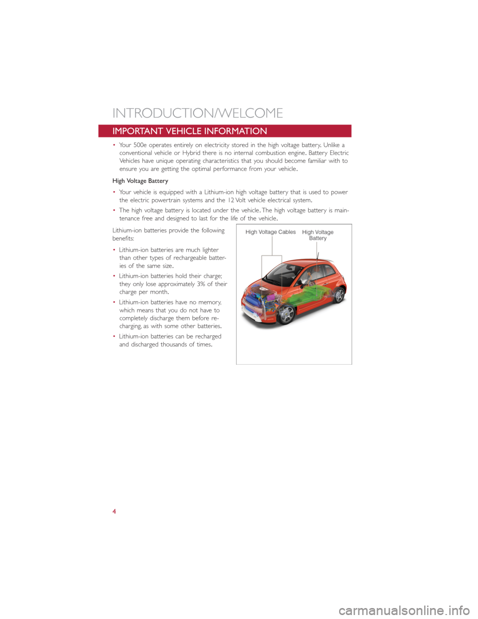
•Your vehicle is equipped with a Lithium-ion high voltage battery that is used to power
the electric powertrain systems and the 12 Volt vehicle electrical system.
•The high voltage battery is located under the vehicle.The high voltage battery is main-
tenance free and designed to last for the life of the vehicle.
Lithium-ion batteries provide the following
benefits:
•Lithium-ion batteries are much lighter
than other types of rechargeable batter-
ies of the same size.
•Lithium-ion batteries hold their charge;
they only lose approximately 3% of their
charge per month.
•Lithium-ion batteries have no memory,
which means that you do not have to
completely discharge them before re-
charging, as with some other batteries.
•Lithium-ion batteries can be recharged
and discharged thousands of times.
INTRODUCTION/WELCOME
4
Page 59 of 92
Partial Off
This mode is entered by momentarily pressing the ESC Off switch.This mode is intended
for times when a more spirited driving experience is desired.It is also intended for driv-
ing in deep snow, sand or gravel conditions, when more wheel spin than ESC would nor-
mally allow is required to gain traction.To turn ESC on again, momentarily press the
switch again.This will restore the normal ESC On mode of operation.
Full Off
This mode is intended for off-highway or off-road use only and should not be used on
public roadways.In this mode, all TCS and ESC stability features are turned OFF, except
for the limited slip feature described in the TCS section.To enter the “Full Off ” mode,
depress and hold the ESC OFF switch for five seconds.After five seconds, the ESC OFF
Indicator Light will illuminate, and the “ESC OFF” message will display in the EVIC.To turn
ESC ON again, momentarily press the ESC OFF switch.
- Electronic Stability Control (ESC) Activation / Malfunction
Indicator Light
The “ESC Activation/Malfunction Indicator Light” in the instrument cluster will come on
for four seconds when the ignition switch is turned to the ON/RUN position.If the “ESC
Activation/Malfunction Indicator Light” comes on continuously with the engine running, a
malfunction has been detected in the ESC system.If this light remains on, see your
authorized dealer as soon as possible to have the problem diagnosed and corrected.
NOTE:
•The “ESC Off Indicator Light” and the “ESC Activation/Malfunction Indicator Light”
come on momentarily each time the ignition switch is turned to ON/RUN.
•Each time the ignition is turned to ON/RUN, the ESC system will be ON even if it
was turned off previously.
•ESC Activation/Malfunction Light can blink during a ESC or TC intervention.
- Tire Pressure Monitoring System (TPMS) Light
•Each tire, including the spare (if provided), should be checked monthly when cold and
inflated to the inflation pressure recommended by the vehicle manufacturer on the
vehicle placard or tire inflation pressure label.(If your vehicle has tires of a different
size than the size indicated on the vehicle placard or tire inflation pressure label, you
should determine the proper tire inflation pressure for those tires.)
•As an added safety feature, your vehicle has been equipped with a Tire Pressure Moni-
toring System (TPMS) that illuminates a low tire pressure telltale when one or more
of your tires is significantly under-inflated.Accordingly, when the low tire pressure tell-
tale illuminates, you should stop and check your tires as soon as possible, and inflate
them to the proper pressure.Driving on a significantly under-inflated tire causes the
tire to overheat and can lead to tire failure.Under-inflation also reduces fuel efficiency
and tire tread life, and may affect the vehicle’s handling and stopping ability.
WHAT TO DO IN EMERGENCIES
57
Page 64 of 92
(C) Injecting TIREFIT Sealant Into The Deflated Tire:
Always start the engine before turning ON the TIREFIT kit.
NOTE:
Manual transmission vehicles must have the parking brake engaged and the shift lever in
NEUTRAL.
After pressing the Power Button (4), the sealant (white fluid) will flow from the Sealant
Bottle (1) through the Sealant Hose (6) and into the tire.
NOTE:
Sealant may leak out through the puncture in the tire.
If the sealant (white fluid) does not flow within0–10seconds through the Sealant Hose (6):
1.Press the Power Button (4) to turn Off the TIREFIT kit.Disconnect the Sealant Hose
(6) from the valve stem.Make sure the valve stem is free of debris.Reconnect the
Sealant Hose (6) to the valve stem.Check that the Mode Select Knob (5) is in the
Sealant Mode position and not Air Mode.Press the Power Button (4) to turn On the
TIREFIT kit.
2.Connect the Power Plug (8) to a different 12 Volt power outlet in your vehicle or
another vehicle, if available.Make sure the engine is running before turning ON the
TIREFIT kit.
3.The Sealant Bottle (1) may be empty due to previous use.Call for assistance.
NOTE:
If the Mode Select Knob (5) is on Air Mode and the pump is operating, air will dispense
from the Air Pump Hose (7) only, not the Sealant Hose (6).
If the sealant (white fluid) does flow through the Sealant Hose (6):
1.Continue to operate the pump until sealant is no longer flowing through the hose
(typically takes 30 - 70 seconds).As the sealant flows through the Sealant Hose (6),
the Pressure Gauge (3) can read as high as 70 psi (4.8 Bar).The Pressure Gauge (3)
will decrease quickly from approximately 70 psi (4.8 Bar) to the actual tire pressure
when the Sealant Bottle (1) is empty.
2.The pump will start to inject air into the tire immediately after the Sealant Bottle (1)
is empty.Continue to operate the pump and inflate the tire to the pressure indicated
on the tire pressure label on the driver-side latch pillar (recommended pressure).
Check the tire pressure by looking at the Pressure Gauge (3).
If the tire does not inflate to at least 26 psi (1.8 Bar) pressure within 15 minutes:
The tire is too badly damaged.Do not attempt to drive the vehicle further.Call for assis-
tance.
NOTE:
If the tire becomes over-inflated, press the Deflation Button to reduce the tire pressure
to the recommended inflation pressure before continuing.
WHAT TO DO IN EMERGENCIES
62
Page 68 of 92
Preparations For Jump-Start
•The battery in your vehicle is located in the underhood compartment under the
beauty cover.
1.Set the parking brake, place the transmission into PARK and turn the ignition to OFF/
LOCK.
2.Turn off the heater, radio, and all unnecessary electrical accessories.
3.If using another vehicle to jump-start the battery, park the vehicle within the jumper
cables reach, set the parking brake and make sure the ignition is OFF.
Jump-Starting Procedure
1.Connect the positive(+)end of the jumper cable to the positive(+)post of the dis-
charged vehicle.
2.Connect the opposite end of the positive(+)jumper cable to the positive(+)post of
the booster battery.
3.Connect the negative end(-)of the jumper cable to the negative(-)post of the
booster battery.
4.Connect the opposite end of the negative(-)jumper cable to a good ground (ex-
posed metal part of the discharged vehicle) away from the battery and the high volt-
age cables.
5.Start the engine in the vehicle that has the booster battery, let the engine idle a few
minutes, and then start the the vehicle with the discharged battery.
•Once the vehicle has started, remove the jumper cables in the reverse sequence:
1.Disconnect the negative(-)jumper cable from the ground(-)of the vehicle with the
discharged battery.
2.Disconnect the negative end(-)of the jumper cable from the negative(-)post of the
booster battery.
3.Disconnect the opposite end of the positive(+)jumper cable from the positive(+)
post of the booster battery.
4.Disconnect the positive(+)end of the jumper cable from the positive(+)post of the
discharged vehicle.
•If frequent jump-starting is required to start your vehicle, you should have the battery
and charging system inspected at your authorized dealer.
WHAT TO DO IN EMERGENCIES
66
Page 69 of 92
CAUTION!
•Accessories that can be plugged into the vehicle power outlets draw power from
the vehicle’s battery, even when not in use (i.e., cellular phones, etc.).Eventually, if
plugged in long enough, the vehicle’s battery will discharge sufficiently to degrade
battery life and/or prevent the engine from starting.
•Do not use a portable battery booster pack or any other booster source with a
system voltage greater than 12 Volts or damage to the battery, starter motor, alter-
nator or electrical system may occur.
•Failure to follow these procedures could result in damage to the charging system
of the booster vehicle or the discharged vehicle.
WARNING!
•Do not attempt jump-starting if the battery is frozen.It could rupture or explode
and cause personal injury.
•Take care to avoid the radiator cooling fan whenever the hood is raised.It can
start anytime the ignition switch is on.You can be injured by moving fan blades.
•Remove any metal jewelry such as watch bands or bracelets that might make an
inadvertent electrical contact.You could be seriously injured.
•Batteries contain sulfuric acid that can burn your skin or eyes and generate hydro-
gen gas which is flammable and explosive.Keep open flames or sparks away from
the battery.
•Do not allow vehicles to touch each other as this could establish a ground con-
nection and personal injury could result.
•Failure to follow this procedure could result in personal injury or property damage
due to battery explosion.
•
Do not connect the cable to the negative post (-)
of the discharged battery.The resulting electrical spark could cause the battery to
explode and could result in personal injury.
WHAT TO DO IN EMERGENCIES
67
Page 74 of 92
OPENING THE HOOD
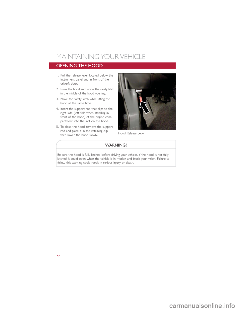
1.Pull the release lever located below the
instrument panel and in front of the
driver’s door.
2.
Raise the hood and locate the safety latch
in the middle of the hood opening.
3.Move the safety latch while lifting the
hood at the same time.
4.Insert the support rod that clips to the
right side (left side when standing in
front of the hood) of the engine com-
partment, into the slot on the hood.
5.To close the hood, remove the support
rod and place it in the retaining clip,
then lower the hood slowly.
WARNING!
Be sure the hood is fully latched before driving your vehicle.If the hood is not fully
latched, it could open when the vehicle is in motion and block your vision.Failure to
follow this warning could result in serious injury or death.
Hood Release Lever
MAINTAINING YOUR VEHICLE
72
Page 76 of 92
FLUIDS AND CAPACITIES
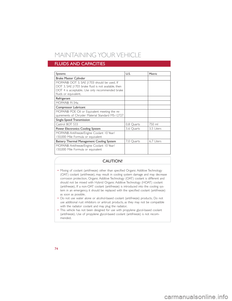
Systems
U.S. Metric
Brake Master Cylinder
MOPAR® DOT 3, SAE J1703 should be used.If
DOT 3, SAE J1703 brake fluid is not available, then
DOT 4 is acceptable.Use only recommended brake
fluids or equivalent.
Refrigerant
MOPAR® R134a
Compressor Lubricant
MOPAR® POE Oil or Equivalent meeting the re-
quirements of Chrysler Material Standard MS-12727
Single-Speed Transmission
Castrol BOT 533 0.8 Quarts 750 ml
Power Electronics Cooling System3.6 Quarts 3.5 Liters
MOPAR® Antifreeze/Engine Coolant 10 Year/
150,000 Mile Formula or equivalent
Battery Thermal Management Cooling System7.0 Quarts 6.7 Liters
MOPAR® Antifreeze/Engine Coolant 10 Year/
150,000 Mile Formula or equivalent
CAUTION!
•Mixing of coolant (antifreeze) other than specified Organic Additive Technology
(OAT) coolant (antifreeze), may result in cooling system damage and may decrease
corrosion protection.Organic Additive Technology (OAT) coolant is different and
should not be mixed with Hybrid Organic Additive Technology (HOAT) coolant
(antifreeze).If a non-OAT coolant (antifreeze) is introduced into the cooling sys-
tem in an emergency, it should be replaced with the specified coolant (antifreeze)
as soon as possible.
•Do not use water alone or alcohol-based coolant (antifreeze) products.Do not
use additional rust inhibitors or antirust products, as they may not be compatible
with the radiator coolant and may plug the radiator.
•This vehicle has not been designed for use with propylene glycol-based coolant
(antifreeze).Use of propylene glycol-based coolant (antifreeze) is not recom-
mended.
MAINTAINING YOUR VEHICLE
74
Page 84 of 92
FIAT CUSTOMER CENTER
P.O.Box 21–8004 Auburn Hills, MI 48321–8004 Phone: 1–800–423–6343
ASSISTANCE FOR THE HEARING IMPAIRED
•To assist customers who have hearing difficulties, the manufacturer has installed special
TDD (Telecommunication Devices for the Deaf ) equipment at its customer center.
Any hearing or speech impaired customer, who has access to a TDD or a conventional
teletypewriter (TTY) in the United States, can communicate with the manufacturer by
dialing 1–800–380–CHRY.
WARNING!
Engine exhaust, some of its constituents, and certain vehicle components contain, or
emit, chemicals known to the State of California to cause cancer and birth defects, or
other reproductive harm.In addition, certain fluids contained in vehicles and certain
products of component wear contain, or emit, chemicals known to the State of
California to cause cancer and birth defects, or other reproductive harm.
PUBLICATIONS ORDERING
•If you are the first registered retail owner of your vehicle,you may obtain one free
printed copy of the Owner's Manual, Warranty Booklet or Radio Manuals on your
DVD by calling 1–888–242–6342 or by contacting your authorized dealer.
•Replacement English User Guide kits or DVDs may be purchased by visiting
www.techauthority.com or by calling 1–800–890–4038.Visa, Master Card, American
Express and Discover orders are accepted.If you prefer mailing your order, please call
the above numbers for an order form.
NOTE:
A street address is required when ordering manuals (no P.O.Boxes).
CUSTOMER ASSISTANCE
82
Page 88 of 92
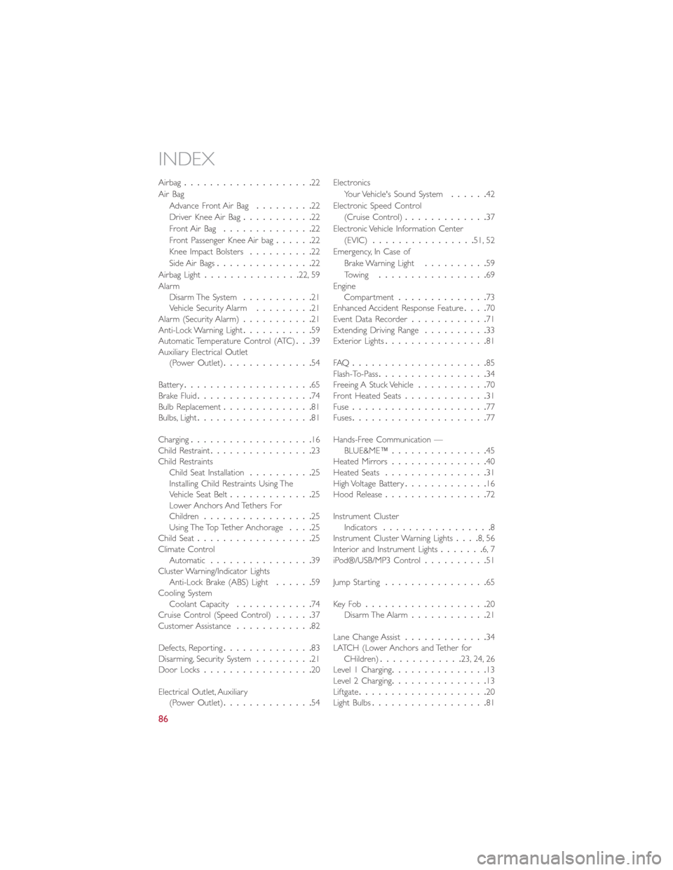
Airbag....................22
Air Bag
Advance Front Air Bag.........22
Driver Knee Air Bag...........22
Front Air Bag..............22
Front Passenger Knee Air bag......22
Knee Impact Bolsters..........22
Side Air Bags...............22
Airbag Light...............22, 59
Alarm
Disarm The System...........21
Vehicle Security Alarm.........21
Alarm (Security Alarm)...........21
Anti-Lock Warning Light...........59
Automatic Temperature Control (ATC)...39
Auxiliary Electrical Outlet
(Power Outlet)..............54
Battery....................65
Brake Fluid..................74
Bulb Replacement..............81
Bulbs, Light..................81
Charging...................16
Child Restraint................23
Child Restraints
Child Seat Installation..........25
Installing Child Restraints Using The
Vehicle Seat Belt.............25
Lower Anchors And Tethers For
Children.................25
Using The Top Tether Anchorage....25
Child Seat..................25
Climate Control
Automatic................39
Cluster Warning/Indicator Lights
Anti-Lock Brake (ABS) Light......59
Cooling System
Coolant Capacity............74
Cruise Control (Speed Control)......37
Customer Assistance............82
Defects, Reporting..............83
Disarming, Security System
.........21
Door Locks.................20
Electrical Outlet, Auxiliary
(Power Outlet)..............54Electronics
Your Vehicle's Sound System......42
Electronic Speed Control
(Cruise Control).............37
Electronic Vehicle Information Center
(EVIC)................51, 52
Emergency, In Case of
Brake Warning Light..........59
Towing.................69
Engine
Compartment..............73
Enhanced Accident Response Feature....70
Event Data Recorder............71
Extending Driving Range..........33
Exterior Lights................81
FAQ.....................85
Flash-To-Pass.................34
Freeing A Stuck Vehicle...........70
Front Heated Seats.............31
Fuse.....................77
Fuses.....................77
Hands-Free Communication —
BLUE&ME™...............45
Heated Mirrors...............40
Heated Seats................31
High Voltage Battery.............16
Hood Release................72
Instrument Cluster
Indicators.................8
Instrument Cluster Warning Lights....8, 56
Interior and Instrument Lights.......6, 7
iPod®/USB/MP3 Control..........51
Jump Starting................65
Key Fo b...................20
Disarm The Alarm............21
Lane Change Assist
.............34
LATCH (Lower Anchors and Tether for
CHildren).............23, 24, 26
Level 1 Charging...............13
Level 2 Charging...............13
Liftgate....................20
Light Bulbs..................81
INDEX
86