ECO mode FIAT 500E 2015 2.G User Guide
[x] Cancel search | Manufacturer: FIAT, Model Year: 2015, Model line: 500E, Model: FIAT 500E 2015 2.GPages: 100, PDF Size: 2.97 MB
Page 45 of 100
Sun Shade
•For vehicles equipped with either a power sunroof or a fixed glass roof, there is a sun
shade that can be open or closed.To open the sun shade push the tab and move the
shade to a full open position.
WARNING!
•Do not let children play with the sunroof, or leave children unattended in the ve-
hicle, and do not leave the key in or near the vehicle (or in a location accessible
to children).Occupants, particularly unattended children, can become entrapped by
the power sunroof while operating the power sunroof switch.Such entrapment
may result in serious injury or death.
•In a collision, there is a greater risk of being thrown from a vehicle with an open
sunroof.You could also be seriously injured or killed.Always fasten your seat belt
properly and make sure all passengers are properly secured.
•Do not allow small children to operate the sunroof.Never allow your fingers,
other body parts, or any object to project through the sunroof opening.Injury
may result.
WIND BUFFETING
•Wind buffeting can be described as a helicopter-type percussion sound.If buffeting
occurs with the windows down, or top down (convertible models), adjust one or both
side windows up or down slightly.
OPERATING YOUR VEHICLE
43
Page 56 of 100
•The iPod® battery charges when plugged into the USB port (if supported by the spe-
cific audio device).
•Compatible iPod® devices may also be controllable using voice commands.Refer to
the BLUE&ME™ Manual on the DVD for details.
NOTE:
The USB port supports certain Mini, Classic, Nano, Touch, and iPhone® devices.The USB
port also supports playing music from compatible external USB Mass Storage Class
memory devices.For supported audio file formats, refer to the USB Port section on the
Owner's Manual on the DVD.Some iPod® software versions may not fully support the
USB port features.Please visit Apple’s website for iPod® software updates.
WARNING!
Do not plug in or remove the iPod® or external device while driving.Failure to follow
this warning could result in a collision.
ELECTRONIC VEHICLE INFORMATION CENTER (EVIC)
•The EVIC features a driver interactive display that is located in the instrument cluster.
Pushing the controls on the right side of the Instrument Cluster allows the driver to
select vehicle information and Personal Settings.For additional information, refer to
“Programmable Features” in this guide.
•Push the MENU button to enter the menu mode.
•Push the UPor DOWNbuttons to scroll through the menu settings.
•Once the menu setting is shown in the EVIC display, push the MENU button to access
the setting and use the UP or DOWN buttons to change the current setting.Push the
MENU button a second time to save the setting and return to menu screen.
ELECTRONICS
54
Page 57 of 100
PROGRAMMABLE FEATURES
Electronic Vehicle Information Center (EVIC)
•Push the MENU button to enter the menu mode.
•Push the UPor DOWNbuttons to scroll through the menu settings.
•Once the menu setting is shown in the EVIC display push the MENU button to access
the setting and use the UP or DOWN buttons to change the current setting.Push the
MENU button a second time to save the setting and return to menu screen.
•Charging Schedule•Daytime Running Lights
•Set Date•Button Volume
•Set Time•Hill Start Assist
•Units•Stored Warning
•Languages•Tutorial
•Battery % Display•Connectivity ID
•Auto Door Lock•Restore Factory Settings
•Remote Unlock•Exit Menu
Selecting An Option Of The Main Menu Without Submenu:
•Briefly push the MENU button to select the main menu option to set.
•Push the UP or DOWN button to select the new setting.
•Briefly push the MENU button to store the new setting and go back to the main
menu option previously selected.
Selecting An Option Of The Main Menu With Submenu:
•Briefly push the MENU button to display the first submenu option.
•Push the UP or DOWN button to scroll through all the submenu options.
•Briefly push the MENU button to select the displayed submenu option and to open
the relevant setup menu.
•Push the UP or DOWN button to select the new setting for this submenu option.
•Briefly push the MENU button to store the new setting and go back to the previously
selected submenu option.
•Push and hold the MENU button to return to the main menu (short hold) or the
main screen (longer hold).
NOTE:
The charging schedule is based on the date and time programmed in the EVIC.
ELECTRONICS
55
Page 67 of 100
Using The Deflation Button
Push the Deflation Button (2) to reduce the air pressure in the tire if it becomes over-
inflated.
Tire Service Kit Usage Precautions
•Replace the Tire Service Kit Sealant Bottle (1) and Sealant Hose (6) prior to the expi-
ration date (printed on the bottle label) to assure optimum operation of the system.
Refer to “Sealing A Tire With Tire Service Kit” section (F) “Sealant Bottle and Hose
Replacement.”
•The Sealant Bottle (1) and Sealant Hose (6) are a one tire application use.After each
use, always replace these components immediately at an authorized dealer.
•When the Tire Service Kit sealant is in a liquid form, clean water, and a damp cloth will
remove the material from the vehicle or tire and wheel components.Once the sealant
dries, it can easily be peeled off and properly discarded.
•For optimum performance, make sure the valve stem on the wheel is free of debris
before connecting the Tire Service Kit.
•You can use the Tire Service Kit air pump to inflate bicycle tires.The kit also comes
with two needles, located in the Accessory Storage Compartment (on the bottom of
the air pump) for inflating sport balls, rafts, or similar inflatable items.However, use
only the Air Pump Hose (7) and make sure the Mode Select Knob (5) is in the Air
Mode when inflating such items to avoid injecting sealant into them.The Tire Service
Kit Sealant is only intended to seal punctures less than 1/4 inch (6 mm) diameter in
the tread of your vehicle.
•Do not lift or carry the Tire Service Kit by the hoses.
Sealing A Tire With Tire Service Kit
(A) Whenever You Stop To Use Tire Service Kit:
1.Pull over to a safe location and turn on the vehicle’s Hazard Warning flashers.
2.Verify that the valve stem (on the wheel with the deflated tire) is in a position that is
near to the ground.This will allow the Tire Service Kit Hoses (6) and (7) to reach the
valve stem and keep the Tire Service Kit flat on the ground.This will provide the best
positioning of the kit when injecting the sealant into the deflated tire and running the
air pump.Move the vehicle as necessary to place the valve stem in this position be-
fore proceeding.
3.Place the transmission in PARK (auto transmission) or in Gear (manual transmission)
and cycle the ignition to the OFF position.
4.Set the parking brake.
(B) Setting Up To Use Tire Service Kit:
1.Turn the Mode Select Knob (5) to the Sealant Mode position.
2.Uncoil the Sealant Hose (6) and then remove the cap from the fitting at the end of
the hose.
WHAT TO DO IN EMERGENCIES
65
Page 68 of 100
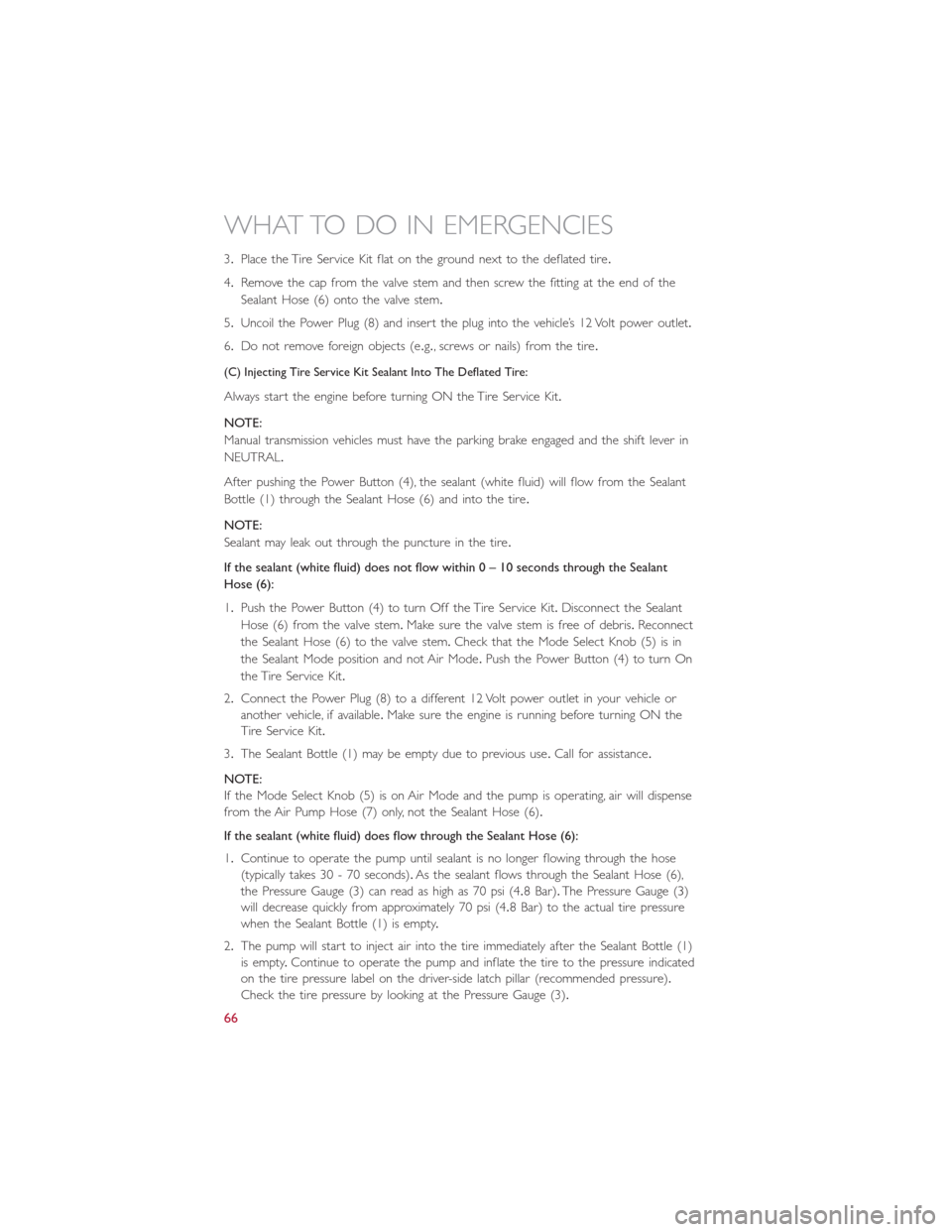
3.Place the Tire Service Kit flat on the ground next to the deflated tire.
4.Remove the cap from the valve stem and then screw the fitting at the end of the
Sealant Hose (6) onto the valve stem.
5.Uncoil the Power Plug (8) and insert the plug into the vehicle’s 12 Volt power outlet.
6.Do not remove foreign objects (e.g., screws or nails) from the tire.
(C) Injecting Tire Service Kit Sealant Into The Deflated Tire:
Always start the engine before turning ON the Tire Service Kit.
NOTE:
Manual transmission vehicles must have the parking brake engaged and the shift lever in
NEUTRAL.
After pushing the Power Button (4), the sealant (white fluid) will flow from the Sealant
Bottle (1) through the Sealant Hose (6) and into the tire.
NOTE:
Sealant may leak out through the puncture in the tire.
If the sealant (white fluid) does not flow within 0 – 10seconds through the Sealant
Hose (6):
1.Push the Power Button (4) to turn Off the Tire Service Kit.Disconnect the Sealant
Hose (6) from the valve stem.Make sure the valve stem is free of debris.Reconnect
the Sealant Hose (6) to the valve stem.Check that the Mode Select Knob (5) is in
the Sealant Mode position and not Air Mode.Push the Power Button (4) to turn On
the Tire Service Kit.
2.Connect the Power Plug (8) to a different 12 Volt power outlet in your vehicle or
another vehicle, if available.Make sure the engine is running before turning ON the
Tire Service Kit.
3.The Sealant Bottle (1) may be empty due to previous use.Call for assistance.
NOTE:
If the Mode Select Knob (5) is on Air Mode and the pump is operating, air will dispense
from the Air Pump Hose (7) only, not the Sealant Hose (6).
If the sealant (white fluid) does flow through the Sealant Hose (6):
1.Continue to operate the pump until sealant is no longer flowing through the hose
(typically takes 30 - 70 seconds).As the sealant flows through the Sealant Hose (6),
the Pressure Gauge (3) can read as high as 70 psi (4.8 Bar).The Pressure Gauge (3)
will decrease quickly from approximately 70 psi (4.8 Bar) to the actual tire pressure
when the Sealant Bottle (1) is empty.
2.The pump will start to inject air into the tire immediately after the Sealant Bottle (1)
is empty.Continue to operate the pump and inflate the tire to the pressure indicated
on the tire pressure label on the driver-side latch pillar (recommended pressure).
Check the tire pressure by looking at the Pressure Gauge (3).
WHAT TO DO IN EMERGENCIES
66
Page 69 of 100
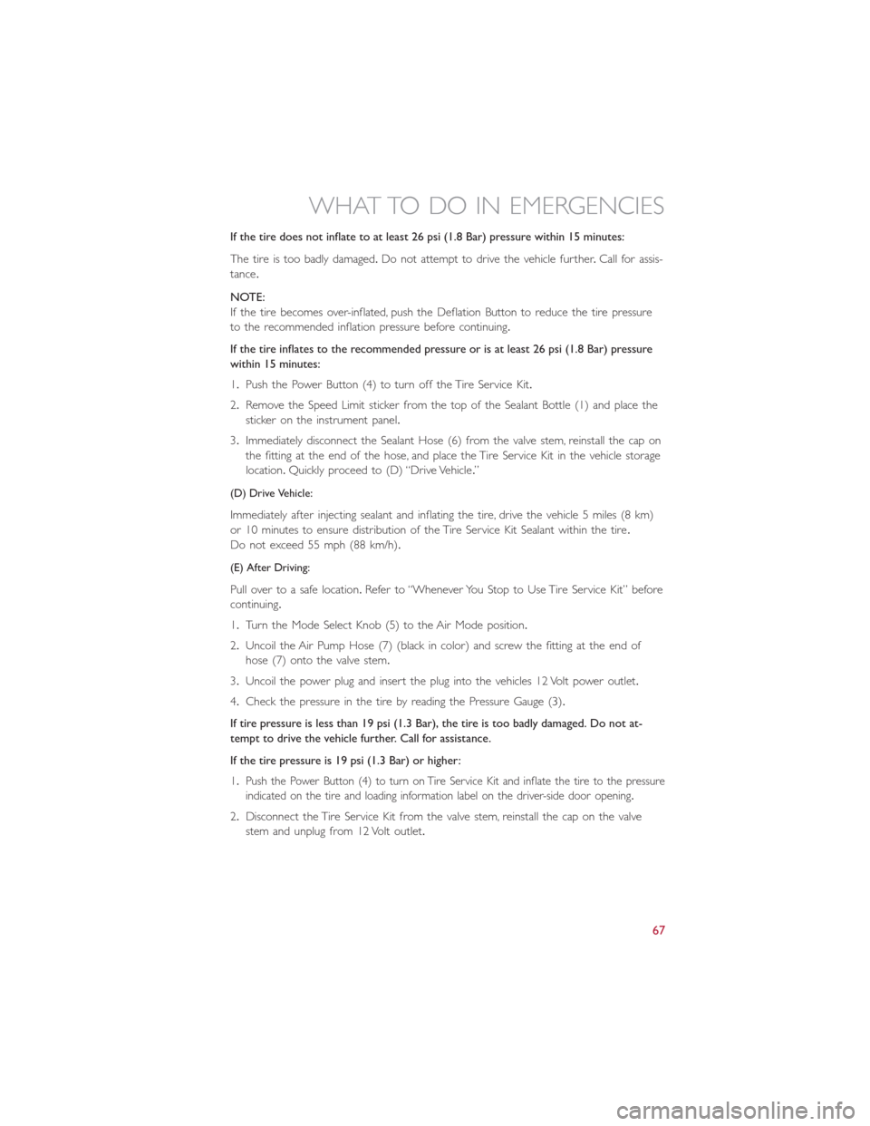
If the tire does not inflate to at least 26 psi (1.8 Bar) pressure within 15 minutes:
The tire is too badly damaged.Do not attempt to drive the vehicle further.Call for assis-
tance.
NOTE:
If the tire becomes over-inflated, push the Deflation Button to reduce the tire pressure
to the recommended inflation pressure before continuing.
If the tire inflates to the recommended pressure or is at least 26 psi (1.8 Bar) pressure
within 15 minutes:
1.Push the Power Button (4) to turn off the Tire Service Kit.
2.Remove the Speed Limit sticker from the top of the Sealant Bottle (1) and place the
sticker on the instrument panel.
3.Immediately disconnect the Sealant Hose (6) from the valve stem, reinstall the cap on
the fitting at the end of the hose, and place the Tire Service Kit in the vehicle storage
location.Quickly proceed to (D) “Drive Vehicle.”
(D) Drive Vehicle:
Immediately after injecting sealant and inflating the tire, drive the vehicle 5 miles (8 km)
or 10 minutes to ensure distribution of the Tire Service Kit Sealant within the tire.
Do not exceed 55 mph (88 km/h).
(E) After Driving:
Pull over to a safe location.Refer to “Whenever You Stop to Use Tire Service Kit” before
continuing.
1.Turn the Mode Select Knob (5) to the Air Mode position.
2.Uncoil the Air Pump Hose (7) (black in color) and screw the fitting at the end of
hose (7) onto the valve stem.
3.Uncoil the power plug and insert the plug into the vehicles 12 Volt power outlet.
4.Check the pressure in the tire by reading the Pressure Gauge (3).
If tire pressure is less than 19 psi (1.3 Bar), the tire is too badly damaged. Do not at-
tempt to drive the vehicle further. Call for assistance.
If the tire pressure is 19 psi (1.3 Bar) or higher:
1.Push the Power Button (4) to turn on Tire Service Kit and inflate the tire to the pressure
indicated on the tire and loading information label on the driver-side door opening.
2.Disconnect the Tire Service Kit from the valve stem, reinstall the cap on the valve
stem and unplug from 12 Volt outlet.
WHAT TO DO IN EMERGENCIES
67
Page 75 of 100
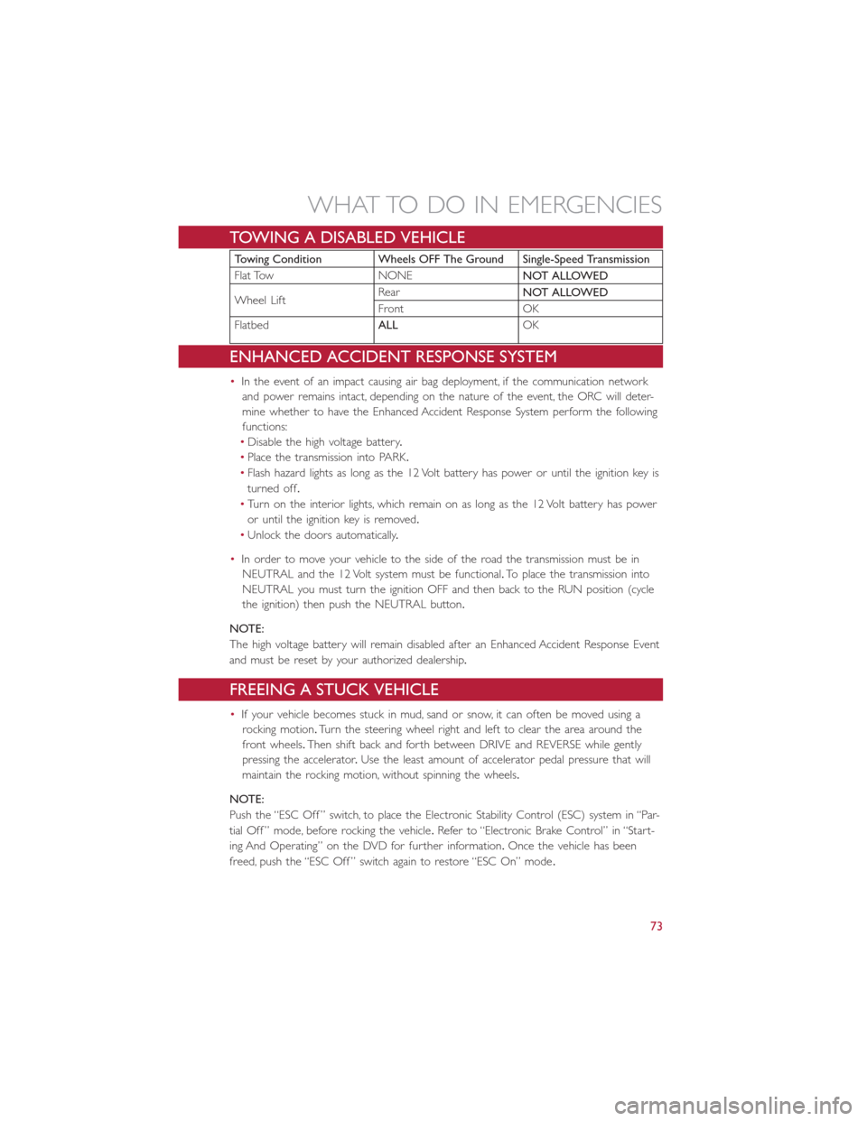
TOWING A DISABLED VEHICLE
Towing Condition Wheels OFF The Ground Single-Speed Transmission
Flat Tow NONENOT ALLOWED
Wheel LiftRearNOT ALLOWED
Front OK
FlatbedALLOK
ENHANCED ACCIDENT RESPONSE SYSTEM
•In the event of an impact causing air bag deployment, if the communication network
and power remains intact, depending on the nature of the event, the ORC will deter-
mine whether to have the Enhanced Accident Response System perform the following
functions:
•Disable the high voltage battery.
•Place the transmission into PARK.
•Flash hazard lights as long as the 12 Volt battery has power or until the ignition key is
turned off.
•Turn on the interior lights, which remain on as long as the 12 Volt battery has power
or until the ignition key is removed.
•Unlock the doors automatically.
•In order to move your vehicle to the side of the road the transmission must be in
NEUTRAL and the 12 Volt system must be functional.To place the transmission into
NEUTRAL you must turn the ignition OFF and then back to the RUN position (cycle
the ignition) then push the NEUTRAL button.
NOTE:
The high voltage battery will remain disabled after an Enhanced Accident Response Event
and must be reset by your authorized dealership.
FREEING A STUCK VEHICLE
•If your vehicle becomes stuck in mud, sand or snow, it can often be moved using a
rocking motion.Turn the steering wheel right and left to clear the area around the
front wheels.Then shift back and forth between DRIVE and REVERSE while gently
pressing the accelerator.Use the least amount of accelerator pedal pressure that will
maintain the rocking motion, without spinning the wheels.
NOTE:
Push the “ESC Off ” switch, to place the Electronic Stability Control (ESC) system in “Par-
tial Off ” mode, before rocking the vehicle.Refer to “Electronic Brake Control” in “Start-
ing And Operating” on the DVD for further information.Once the vehicle has been
freed, push the “ESC Off ” switch again to restore “ESC On” mode.
WHAT TO DO IN EMERGENCIES
73
Page 98 of 100
Oil, Engine..................79Change Interval.............79Checking................79Disposal.................79Filter..................79Filter Disposal..............79Materials Added to...........79Recommendation............79Viscosity.................79Oil Filter, Selection..............79
Paint Care..................79Phone (Pairing)...............51Placard, Tire and Loading Information....85PowerDoor Locks...............20Steering.................60Programmable Electronic Features.....55
Radio (Sound Systems)...........46Reclining Front Seats............30Recreational Towing.............58Refrigerant..................79Remote Keyless Entry (RKE)Disarm The Alarm............20Replacement Bulbs.............89Reporting Safety Defects..........91Rotation, Tires................86
Schedule, Maintenance............79Seat BeltEngage The Automatic LockingMode..................26Seat Belt Maintenance............79Seat Belts..................20Reminder................60Seat Belt Warning............21SeatsAdjustment...............30Heated.................33Security Alarm................63Disarm The System...........20Security Alarm..............20Selection of Coolant (Antifreeze)......78
Signals, Turn...............36, 63Spare Tire................87, 88Speed ControlAccel/Decel...............39Cancel..................40Speed Control (Cruise Control)......38Store Radio Presets.............47Stuck, Freeing................73Supplemental Restraint System - Airbag...21
TiresAir Pressure...............85Compact Spare.............87Pressure Warning Light.........61Rotation.................86Tire Service Kit.............63, 64Towing....................58Disabled Vehicle.............73Recreational...............58Towing Vehicle Behind a Motorhome....58Trailer TowingTrailer and Tongue Weight.......58Trailer Weight................58TransmissionCapacities................78Fluid.................78, 79Maintenance..............79Turn Signals...............36, 63
Uconnect® (Hands-Free Phone)Making A Phone Call..........52
Vehicle Security Alarm Disarming......20
WasherAdding Fluid...............79Rear...................38Washing Vehicle...............79Wheel and Wheel Trim...........79Wheel and Wheel Trim Care......79, 88Wind Buffeting...............43Windshield Wiper Blades..........79Wiper Blade Replacement..........79Wiper, Rear.................38
INDEX
96