warning FIAT 500E 2016 2.G Repair Manual
[x] Cancel search | Manufacturer: FIAT, Model Year: 2016, Model line: 500E, Model: FIAT 500E 2016 2.GPages: 362, PDF Size: 2.58 MB
Page 152 of 362
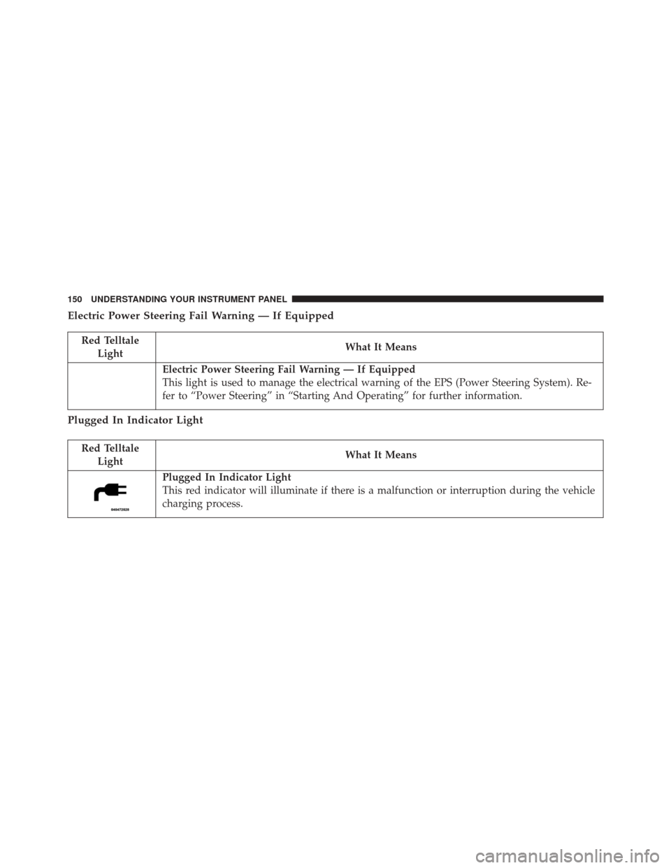
Electric Power Steering Fail Warning — If Equipped
Red TelltaleLight What It Means
Electric Power Steering Fail Warning — If Equipped
This light is used to manage the electrical warning of the EPS (Power Steering System). Re-
fer to “Power Steering” in “Starting And Operating” for further information.
Plugged In Indicator Light
Red Telltale
Light What It Means
Plugged In Indicator Light
This red indicator will illuminate if there is a malfunction or interruption during the vehicle
charging process.
150 UNDERSTANDING YOUR INSTRUMENT PANEL
Page 153 of 362
Door Open Warning Light
Red Telltale LightWhat It Means
Door Open Warning Light
This indicator will illuminate when a door is ajar/open and not fully closed.
•Driver ’s Door Open
• Passenger Door Open
• Driver and Passenger Door Open 4
UNDERSTANDING YOUR INSTRUMENT PANEL 151
Page 154 of 362
Service Propulsion System Warning Light
Red TelltaleLight What It Means
Service Propulsion System Warning Light
The Service Propulsion System Warning Light will illuminate if there is a malfunction de-
tected with the Propulsion System. If the light comes on or remains on while driving see
your authorized dealer.
Battery Charge Warning Light
Red Telltale
Light What It Means
Battery Charge Warning Light
This light illuminates when the battery is not charging properly. If it stays on while the en-
gine is running, there may be a malfunction with the charging system. Contact your autho-
rized dealer as soon as possible. This indicates a possible problem with the electrical system
or a related component.
152 UNDERSTANDING YOUR INSTRUMENT PANEL
Page 155 of 362
Red TelltaleLight What It Means
If jump starting is required, refer to “Jump Starting Procedures” in “What To Do In Emer-
gencies.”
Liftgate Open Warning Light
Red Telltale Light What It Means
Liftgate Open Warning Light
This indicator will turn when the liftgate is open.
4
UNDERSTANDING YOUR INSTRUMENT PANEL 153
Page 158 of 362
Electronic Stability Control (ESC) OFF Indicator Light — If Equipped
Yellow TelltaleLight What It Means
Electronic Stability Control (ESC) OFF Indicator Light — If Equipped
This light indicates the Electronic Stability Control (ESC) is off.
Tire Pressure Monitoring Indicator Light
Yellow Telltale
Light What It Means
Tire Pressure Monitoring Indicator Light
The warning light switches on and a message is displayed to indicate that the tire pressure
is lower than the recommended value and/or that slow pressure loss is occurring. In these
cases, optimal tire duration and battery charge efficiency may not be guaranteed.
Should two or more tires be in the condition mentioned above, the display will show the
indications corresponding to each tire in sequence.
156 UNDERSTANDING YOUR INSTRUMENT PANEL
Page 160 of 362
approximately one minute and then remain continuously
illuminated. This sequence will continue upon subse-
quent vehicle start-ups as long as the malfunction exists.
When the malfunction indicator is illuminated, the sys-
tem may not be able to detect or signal low tire pressure
as intended. TPMS malfunctions may occur for a variety
of reasons, including the installation of replacement or
alternate tires or wheels on the vehicle that prevent the
TPMS from functioning properly. Always check the
TPMS malfunction telltale after replacing one or more
tires or wheels on your vehicle, to ensure that the
replacement or alternate tires and wheels allow the TPMS
to continue to function properly.CAUTION!
The TPMS has been optimized for the original
equipment tires and wheels. TPMS pressures and
warning have been established for the tire size
equipped on your vehicle. Undesirable system opera-
tion or sensor damage may result when using re-
placement equipment that is not of the same size,
type, and/or style. Aftermarket wheels can cause
sensor damage. Using aftermarket tire sealants may
cause the Tire Pressure Monitoring System (TPMS)
sensor to become inoperable. After using an after-
market tire sealant it is recommended that you take
your vehicle to an authorized dealership to have your
sensor function checked.
158 UNDERSTANDING YOUR INSTRUMENT PANEL
Page 162 of 362
Anti-Lock Brake (ABS) Indicator Light
Yellow TelltaleLight What It Means
Anti-Lock Brake (ABS) Indicator Light
This light monitors the Anti-Lock Brake System (ABS). The light will turn on when the igni-
tion switch is placed in the ON/RUN position and may stay on for as long as four seconds.
If the ABS light remains on or turns on while driving, then the Anti-Lock portion of the
brake system is not functioning and service is required. However, the conventional brake
system will continue to operate normally if the brake warning light is not on.
If the ABS light is on, the brake system should be serviced as soon as possible to restore the
benefits of Anti-Lock Brakes. If the ABS light does not turn on when the ignition switch is
placed in the ON/RUN position, have the light inspected by an authorized dealer.
160 UNDERSTANDING YOUR INSTRUMENT PANEL
Page 169 of 362
The EVIC consists of the following:
•System Status
• Vehicle Information Warning Message Displays
• Outside Temperature Display •
Trip Computer Functions
• Tire Pressure Monitoring Display
• Range
EVIC Control Buttons
The EVIC control buttons are located on the right side of
the Instrument Cluster. There are three control buttons
that are used to navigate through the EVIC functions:
•+ button
• – button
• MENU ESC button
Electronic Vehicle Information Center (EVIC) Display
4
UNDERSTANDING YOUR INSTRUMENT PANEL 167
Page 171 of 362
The setup menu can be activated by pushing the MENU
ESC button. Single pushes on the + or – buttons will
scroll through the setup menu options. The menu in-
cludes the following functions:
•Battery % Display
• Button Volume
• Stored Warnings
• Tutorial
• Connectivity ID
• Restore Factory Settings
• Exit Menu
Selecting An Option Of The Main Menu Without
Submenu:
1. Briefly push and release the MENU ESC button to select the main menu option to set. 2. Push and release the + or – button (by single pushes)
to select the new setting.
3. Briefly push and release the MENU ESC button to store the new setting and go back to the main menu
option previously selected.
Selecting An Option Of The Main Menu With Sub-
menu:
1. Briefly push and release the MENU ESC button to display the first submenu option.
2. Push and release the + or – button (by single pushes) to scroll through all the submenu options.
3. Briefly push and release the MENU ESC button to select the displayed submenu option and to open the
relevant setup menu.
4. Push and release the + or – button (by single pushes) to select the new setting for this submenu option.
4
UNDERSTANDING YOUR INSTRUMENT PANEL 169
Page 175 of 362
time and FCA US LLC, working with its suppliers,
evaluates and takes appropriate steps as needed. Similar
to a computer or other devices, your vehicle may require
software updates to improve the usability and perfor-
mance of your systems or to reduce the potential risk of
unauthorized and unlawful access to your vehicle sys-
tems.
The risk of unauthorized and unlawful access to your
vehicle systems may still exist, even if the most recent
version of vehicle software (such as Uconnect software) is
installed.WARNING!
•It is not possible to know or to predict all of the
possible outcomes if your vehicle’s systems are
breached. It may be possible that vehicle systems,
including safety related systems, could be im-
paired or a loss of vehicle control could occur that
may result in an accident involving serious injury
or death.
• ONLY insert media (e.g., USB, SD card, or CD) into
your vehicle if it came from a trusted source. Media
of unknown origin could possibly contain mali-
cious software, and if installed in your vehicle, it
may increase the possibility for vehicle systems to
be breached.
• As always, if you experience unusual vehicle be-
havior, take your vehicle to your nearest authorized
dealer immediately.
4
UNDERSTANDING YOUR INSTRUMENT PANEL 173