brakes FIAT 500E 2016 2.G Owners Manual
[x] Cancel search | Manufacturer: FIAT, Model Year: 2016, Model line: 500E, Model: FIAT 500E 2016 2.GPages: 362, PDF Size: 2.58 MB
Page 162 of 362
Anti-Lock Brake (ABS) Indicator Light
Yellow TelltaleLight What It Means
Anti-Lock Brake (ABS) Indicator Light
This light monitors the Anti-Lock Brake System (ABS). The light will turn on when the igni-
tion switch is placed in the ON/RUN position and may stay on for as long as four seconds.
If the ABS light remains on or turns on while driving, then the Anti-Lock portion of the
brake system is not functioning and service is required. However, the conventional brake
system will continue to operate normally if the brake warning light is not on.
If the ABS light is on, the brake system should be serviced as soon as possible to restore the
benefits of Anti-Lock Brakes. If the ABS light does not turn on when the ignition switch is
placed in the ON/RUN position, have the light inspected by an authorized dealer.
160 UNDERSTANDING YOUR INSTRUMENT PANEL
Page 208 of 362
STARTING PROCEDURES
Before starting your vehicle, adjust your seat, adjust both
inside and outside mirrors, and fasten your seat belts.
WARNING!
•Never leave children alone in a vehicle, or with
access to an unlocked vehicle.
• Allowing children to be in a vehicle unattended is
dangerous for a number of reasons. A child or
others could be seriously or fatally injured. Chil-
dren should be warned not to touch the parking
brake, brake pedal or the gear selector.
• Do not leave the Key Fob in or near the vehicle (or
in a location accessible to children). A child could
operate power windows, other controls, or move
the vehicle.
Single-Speed Transmission
The transmission must be in the PARK or NEUTRAL
position before you can start the vehicle. Apply the
brakes when selecting a transmission gear from Park.
NOTE: You must press the brake pedal before selecting
a transmission gear.
Normal Starting
Turn the key to the START position while your vehicle is
in PARK. When the ignition key is turned to the START
and then released to the RUN position, a chime will
sound and the “READY” indicator in the EVIC will
illuminate to indicate the 500e’s Electric Drive System has
started. When the “READY” indicator is illuminated
your 500e is ready to be driven.
206 STARTING AND OPERATING
Page 218 of 362
Shallow Standing Water
Although your vehicle is capable of driving through
shallow standing water, consider the following Caution
and Warning before doing so.
CAUTION!
•Always check the depth of the standing water
before driving through it. Never drive through
standing water that is deeper than the bottom of
the tire rims mounted on the vehicle.
• Determine the condition of the road or the path
that is under water and if there are any obstacles in
the way before driving through the standing water.
• Do not exceed 5 mph (8 km/h) when driving
through standing water. This will minimize wave
effects.
(Continued)
CAUTION! (Continued)
•Driving through standing water may cause damage
to your vehicle’s drivetrain components. Always
inspect your vehicle’s fluids (i.e., transmission,
coolant, etc.) for signs of contamination (i.e., fluid
that is milky or foamy in appearance) after driving
through standing water. Do not continue to operate
the vehicle if any fluid appears contaminated, as
this may result in further damage. Such damage is
not covered by the New Vehicle Limited Warranty.
• Driving through standing water limits your vehi-
cle’s traction capabilities. Do not exceed 5 mph
(8 km/h) when driving through standing water.
• Driving through standing water limits your vehi-
cle’s braking capabilities, which increases stopping
distances. Therefore, after driving through stand-
ing water, drive slowly and lightly press on the
brake pedal several times to dry the brakes.
(Continued)
216 STARTING AND OPERATING
Page 222 of 362
CAUTION!
If the Brake Warning Light remains on with the
parking brake released, a brake system malfunction
is indicated. Have the brake system serviced by an
authorized dealer immediately.
BRAKE SYSTEM
In the event regenerative braking or power assist is lost
for any reason the brakes will still function. The effort
required to brake the vehicle will be significantly more
than that required with the power system operating.
If either the front or rear hydraulic system loses normal
capability, the remaining system will still function with
some loss of braking effectiveness. This will be evident by
increased pedal travel during application, greater pedalforce required to slow or stop, and activation of the Brake
Warning Light and the ABS Warning Light during brake
use.
ELECTRONIC BRAKE CONTROL SYSTEM
Your vehicle is equipped with a advanced electronic
brake control system that includes the Anti-Lock Brake
System (ABS), Brake Assist System (BAS), Traction Con-
trol System (TCS), and Electronic Stability Control (ESC).
All systems work together to enhance vehicle stability
and control in various driving conditions and are com-
monly referred to as ESC.
Four-Wheel Anti-Lock Brake System (ABS)
The Four-Wheel ABS is designed to aid the driver in
maintaining vehicle control under adverse braking con-
ditions. The system operates with a separate computer to
modulate hydraulic pressure, to prevent wheel lock-up
and to help avoid skidding on slippery surfaces.
220 STARTING AND OPERATING
Page 223 of 362
The system’s pump motor runs during an ABS stop to
provide regulated hydraulic pressure. The pump motor
makes a low humming noise during operation, which is
normal.
The ABS includes an amber ABS Warning Light. When
the light is illuminated, the ABS is not functioning. The
system reverts to standard non-anti-lock brakes. Turning
the ignition Off and On again may reset the ABS if the
fault detected was only momentary.
WARNING!
•Pumping the Anti-Lock Brakes will diminish their
effectiveness and may lead to a collision. Pumping
makes the stopping distance longer. Just press
firmly on your brake pedal when you need to slow
down or stop.
(Continued)
WARNING! (Continued)
•The Anti-Lock Brake System (ABS) cannot prevent
the natural laws of physics from acting on the
vehicle, nor can it increase braking or steering
efficiency beyond that afforded by the condition of
the vehicle brakes and tires or the traction afforded.
• The ABS cannot prevent collisions, including those
resulting from excessive speed in turns, following
another vehicle too closely, or hydroplaning.
• The capabilities of an ABS-equipped vehicle must
never be exploited in a reckless or dangerous
manner, which could jeopardize the user’s safety or
the safety of others.
When you are in a severe braking condition involving the
use of the ABS, you will experience some pedal drop as
the vehicle comes to a stop. This is the result of the
system reverting to the base brake system.
5
STARTING AND OPERATING 221
Page 224 of 362
Engagement of the ABS may be accompanied by a
pulsing sensation. You may also hear a clicking noise.
These occurrences are normal and indicate that the
system is functioning properly.
Brake Assist System (BAS)
The BAS is designed to optimize the vehicle’s braking
capability during emergency braking maneuvers. The
system detects an emergency braking situation by sens-
ing the rate and amount of brake application and then
applies optimum pressure to the brakes. This can help
reduce braking distances. The BAS complements the
Anti-Lock Brake System (ABS). Applying the brakes very
quickly results in the best BAS assistance. To receive the
benefit of the system, you must applycontinuousbrak-
ing pressure during the stopping sequence (do not
“pump” the brakes). Do not reduce brake pedal pressure
unless braking is no longer desired. Once the brake pedal
is released, the BAS is deactivated.
WARNING!
• The Brake Assist System (BAS) cannot prevent the
natural laws of physics from acting on the vehicle,
nor can it increase the traction afforded by prevail-
ing road conditions.
• The BAS cannot prevent collisions, including those
resulting from excessive speed in turns, driving on
very slippery surfaces, or hydroplaning.
• The capabilities of a BAS-equipped vehicle must
never be exploited in a reckless or dangerous
manner which could jeopardize the user ’s safety or
the safety of others.
Traction Control System (TCS)
This system monitors the amount of wheel spin of each of
the driven wheels. If wheel spin is detected, brake
pressure is applied to the slipping wheel(s) and vehicle
power is reduced to provide enhanced acceleration and
222 STARTING AND OPERATING
Page 229 of 362
which propel the vehicle forward can operate as genera-
tors when braking. The RBS recharges the high voltage
battery under certain braking conditions by recapturing
energy that would otherwise be lost while braking. The
electric power that is generated goes back into the high
voltage battery for later use, for example when accelera-
tion is desired.
The RBS uses conventional hydraulic friction brakes,
regenerative braking, or a combination to slow the ve-
hicle. If the system detects slippery conditions while
braking, ONLY friction is used to slow the vehicle. The
RBS can result in extended life of the hydraulic service
brakes; however, all inspection, scheduled maintenance,
and service intervals for the vehicle service brakes must
be followed.TIRE SAFETY INFORMATION
Tire Markings
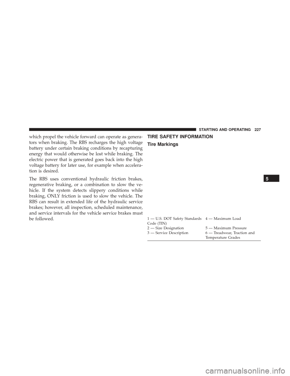
1 — U.S. DOT Safety Standards
Code (TIN)4 — Maximum Load
2 — Size Designation 5 — Maximum Pressure
3 — Service Description 6 — Treadwear, Traction and Temperature Grades
5
STARTING AND OPERATING 227
Page 306 of 362
5. Lower the wiper blade and snap the pivot cap intoplace.
Adding Washer Fluid
The windshield washer fluid reservoir is located in the
underhood compartment, and the fluid level should be
checked at regular intervals. Fill the reservoir with wind-
shield washer solvent (not coolant/ antifreeze). Refer to
“Underhood Compartment” in “Maintaining Your Ve-
hicle” for further information.
WARNING!
Commercially available windshield washer solvents
are flammable. They could ignite and burn you. Care
must be exercised when filling or working around
the washer solution.
Brake System
In order to assure brake system performance, all brake
system components should be inspected periodically.
Refer to the “Maintenance Schedule” for the proper
maintenance intervals.
WARNING!
Riding the brakes can lead to brake failure and
possibly a collision. Driving with your foot resting or
riding on the brake pedal can result in abnormally
high brake temperatures, excessive lining wear, and
possible brake damage. Riding the brakes may also
reduce braking capacity in an emergency.
304 MAINTAINING YOUR VEHICLE
Page 351 of 362
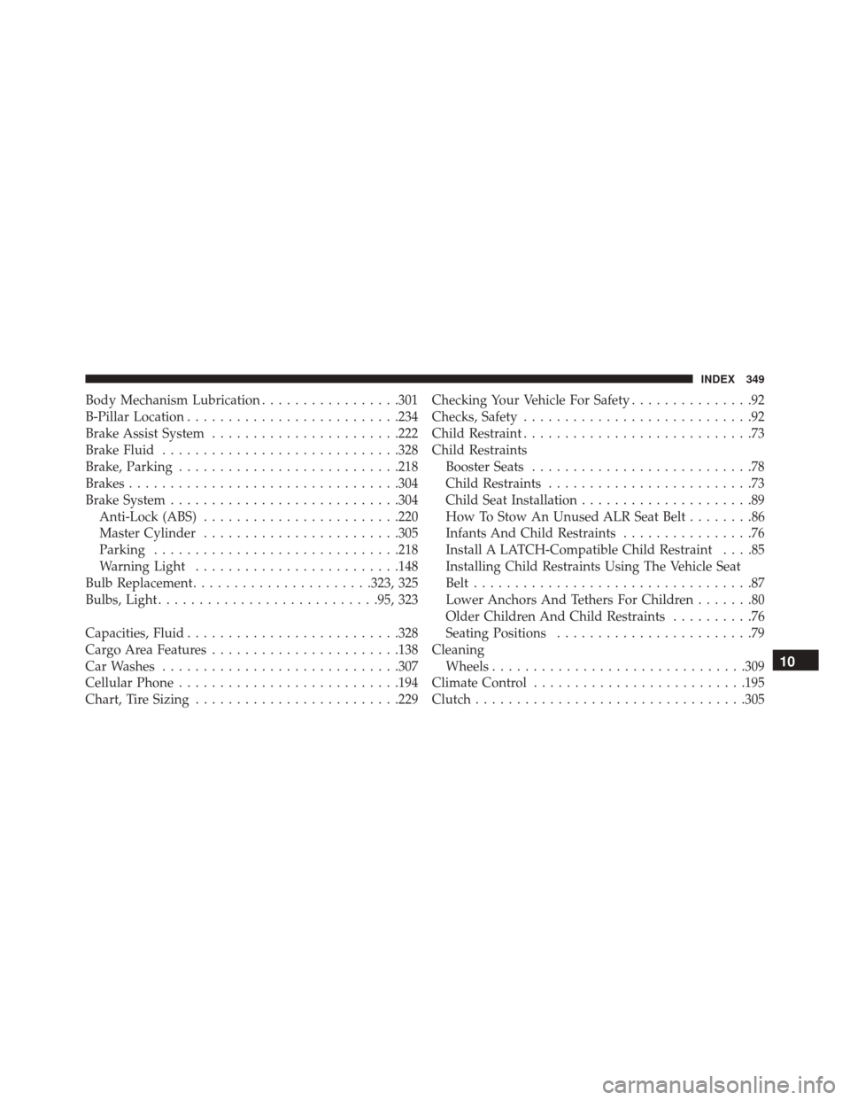
Body Mechanism Lubrication.................301
B-Pillar Location ......................... .234
Brake Assist System ...................... .222
Brake Fluid ............................ .328
Brake, Parking .......................... .218
Brakes ................................ .304
Brake System ........................... .304
Anti-Lock (ABS) ....................... .220
Master Cylinder ....................... .305
Parking ............................. .218
Warning Light ........................ .148
Bulb Replacement ..................... .323, 325
Bulbs, Light .......................... .95, 323
Capacities, Fluid ......................... .328
Cargo Area Features ...................... .138
Car Washes ............................ .307
Cellular Phone .......................... .194
Chart, Tire Sizing ........................ .229Checking Your Vehicle For Safety
...............92
Checks, Safety ............................92
Child Restraint ............................73
Child Restraints Booster Seats ...........................78
Child Restraints .........................73
Child Seat Installation .....................89
How To Stow An Unused ALR Seat Belt ........86
Infants And Child Restraints ................76
Install A LATCH-Compatible Child Restraint ....85
Installing Child Restraints Using The Vehicle Seat
Belt ..................................87
Lower Anchors And Tethers For Children .......80
Older Children And Child Restraints ..........76
Seating Positions ........................79
Cleaning Wheels .............................. .309
Climate Control ......................... .195
Clutch ................................ .305
10
INDEX 349
Page 355 of 362
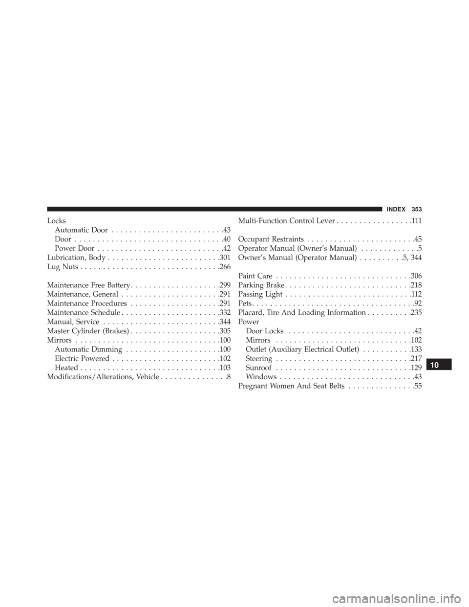
LocksAutomatic Door .........................43
Door .................................40
Power Door ............................42
Lubrication, Body ........................ .301
Lug Nuts .............................. .266
Maintenance Free Battery ....................299
Maintenance, General ..................... .291
Maintenance Procedures ....................291
Maintenance Schedule ..................... .332
Manual, Service ......................... .344
Master Cylinder (Brakes) ....................305
Mirrors ............................... .100
Automatic Dimming .....................100
Electric Powered ....................... .102
Heated .............................. .103
Modifications/Alterations, Vehicle ...............8Multi-Function Control Lever
.................111
Occupant Restraints ........................45
Operator Manual (Owner’s Manual) .............5
Owner’s Manual (Operator Manual) ..........5,344
Paint Care ............................. .306
Parking Brake ........................... .218
Passing Light ............................112
Pets ....................................92
Placard, Tire And Loading Information ..........235
Power Door Locks ............................42
Mirrors ............................. .102
Outlet (Auxiliary Electrical Outlet) ...........133
Steering ............................. .217
Sunroof ............................. .129
Windows ..............................43
Pregnant Women And Seat Belts ...............55
10
INDEX 353