lights FIAT 500E 2016 2.G User Guide
[x] Cancel search | Manufacturer: FIAT, Model Year: 2016, Model line: 500E, Model: FIAT 500E 2016 2.GPages: 132, PDF Size: 4.59 MB
Page 3 of 132

INTRODUCTION/WELCOMEWELCOME FROM FIAT...............2
IMPORTANT VEHICLE INFORMATION......4
CONTROLS AT A GLANCEDRIVER COCKPIT..................6
INSTRUMENT CLUSTER..............8
GETTING STARTEDELECTRIC VEHICLE FEATURES..........10
ELECTRIC SYSTEM OPERATION.........13
CHARGING THE HIGH VOLTAGE BATTERY...16
STARTING YOUR 500e...............19
KEY FOB......................20
VEHICLE SECURITY ALARM...........21
POWER DOOR LOCKS..............21
OCCUPANT RESTRAINT SYSTEMS........21
HEAD RESTRAINTS.................31
SEATS........................33
REAR SEATS.....................37
TILT STEERING COLUMN.............38
OPERATING YOUR VEHICLEEXTENDING YOUR DRIVING RANGE PER
CHARGE.......................39
LIGHTS.......................40
WIPER/WASHER LEVER..............43
ELECTRONIC SPEED CONTROL........44
POWER WINDOWS................47
AUTOMATIC TEMPERATURE CONTROLS
(ATC).........................48
REAR PARK ASSIST.................49
POWER SUNROOF.................50
ELECTRONICSYOUR VEHICLE'S SOUND SYSTEM........52
CYBERSECURITY..................54
IDENTIFYING YOUR RADIO............55
UCONNECT 5.0..................56
USB/AUX CONTROL................60
UCONNECT 5.0 VOICE RECOGNITION
QUICK TIPS.....................61
UCONNECT PHONE...............68
STEERING WHEEL AUDIO CONTROLS.....77
ELECTRONIC VEHICLE INFORMATION
CENTER (EVIC)...................77
PROGRAMMABLE FEATURES...........78
TRIP BUTTON....................79
POWER OUTLET.................80
UTILITY
TRAILER TOWING.................82
RECREATIONAL TOWING (BEHIND
MOTORHOME, ETC.)...............82
WHAT TO DO IN EMERGENCIES
ROADSIDE ASSISTANCE..............83
WARNING AND INDICATOR LIGHTS......83
TIRE SERVICE KIT..................89
JUMP-STARTING PROCEDURE
(12 VOLT BATTERY ONLY)............96
MANUAL PARK RELEASE.............99
TOWING A DISABLED VEHICLE.........100
ENHANCED ACCIDENT RESPONSE SYSTEM..100
FREEING A STUCK VEHICLE...........101
EVENT DATA RECORDER (EDR)........102
MAINTAINING YOUR VEHICLE
OPENING THE HOOD..............103
ENGINE COMPARTMENT — ELECTRIC....104
FLUID CAPACITIES................106
FLUIDS, LUBES, AND GENUINE PARTS.....106
MAINTENANCE PROCEDURES.........107
MAINTENANCE SCHEDULE..........107
FUSES.......................110
TIRES — GENERAL INFORMATION......113
TIRE ROTATION RECOMMENDATIONS....116
REPLACEMENT BULBS..............117
CUSTOMER ASSISTANCE
FIAT CUSTOMER CENTER............118
ASSISTANCE FOR THE HEARING
IMPAIRED.....................118
PUBLICATIONS ORDERING...........118
REPORTING SAFETY DEFECTS IN THE
UNITED STATES..................118
MOPAR® ACCESSORIES
AUTHENTIC ACCESSORIES BY MOPAR....119
FAQ ’s
FREQUENTLY ASKED QUESTIONS.......120
INDEX......................121
TABLE OF CONTENTS
1
Page 8 of 132
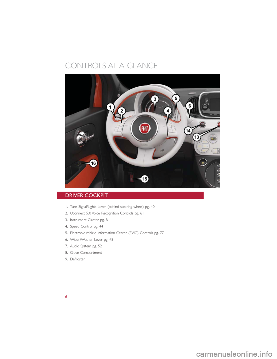
DRIVER COCKPIT
1.Turn Signal/Lights Lever (behind steering wheel) pg.40
2.Uconnect 5.0 Voice Recognition Controls pg.61
3.Instrument Cluster pg.8
4.Speed Control pg.44
5.Electronic Vehicle Information Center (EVIC) Controls pg.77
6.Wiper/Washer Lever pg.43
7.Audio System pg.52
8.Glove Compartment
9.Defroster
CONTROLS AT A GLANCE
6
Page 9 of 132
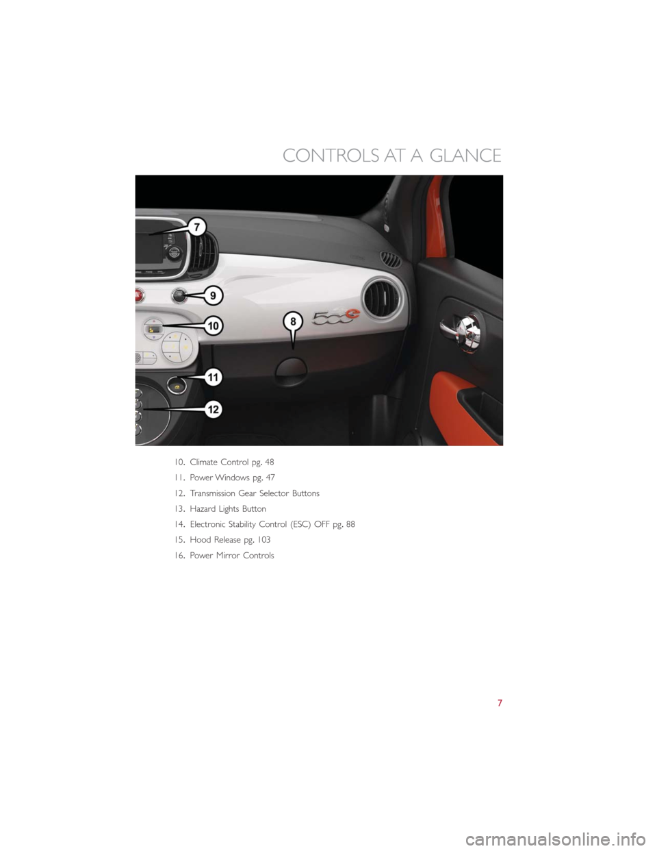
10.Climate Control pg.48
11.Power Windows pg.47
12.Transmission Gear Selector Buttons
13.Hazard Lights Button
14.Electronic Stability Control (ESC) OFF pg.88
15.Hood Release pg.103
16.Power Mirror Controls
CONTROLS AT A GLANCE
7
Page 10 of 132
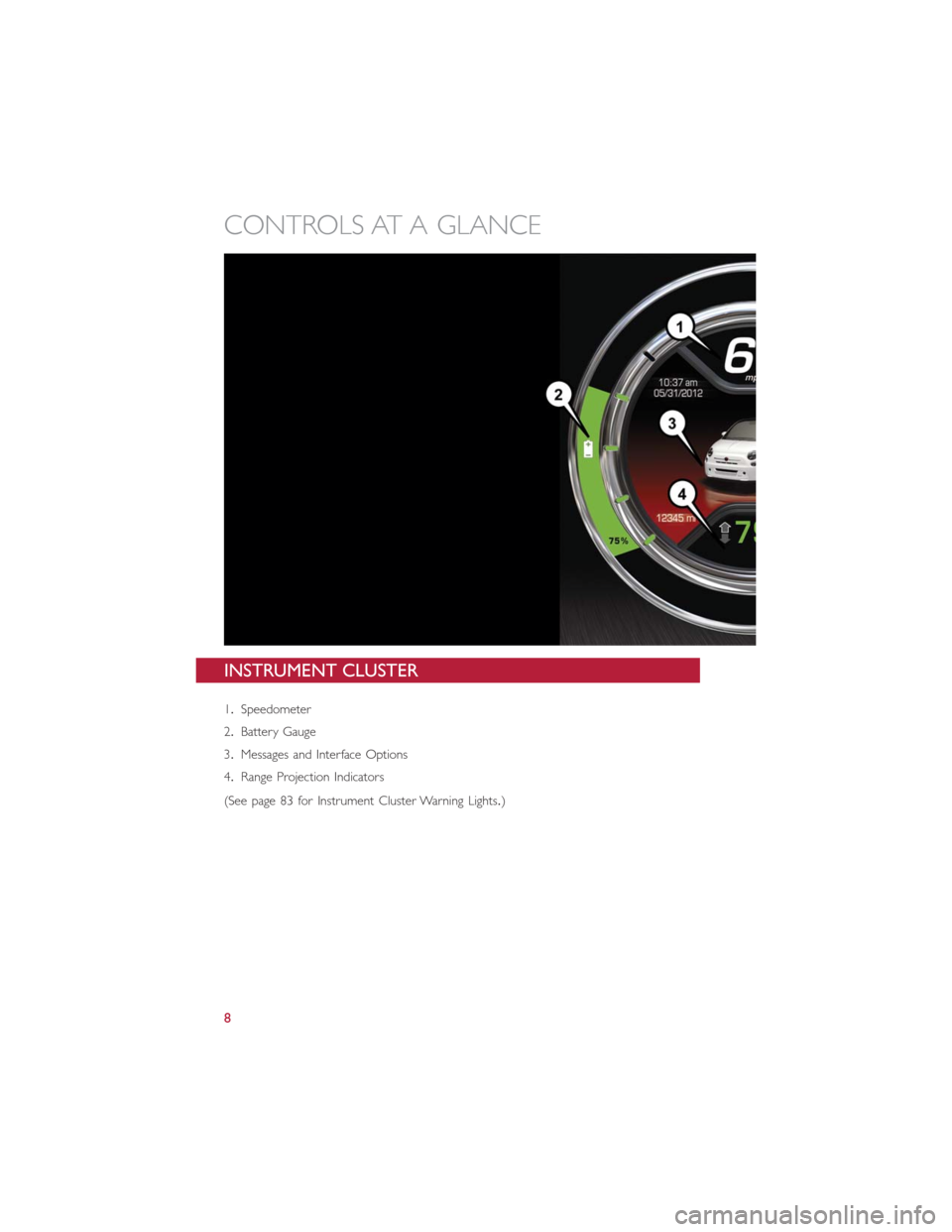
INSTRUMENT CLUSTER
1.Speedometer
2.Battery Gauge
3.Messages and Interface Options
4.Range Projection Indicators
(See page 83 for Instrument Cluster Warning Lights.)
CONTROLS AT A GLANCE
8
Page 11 of 132
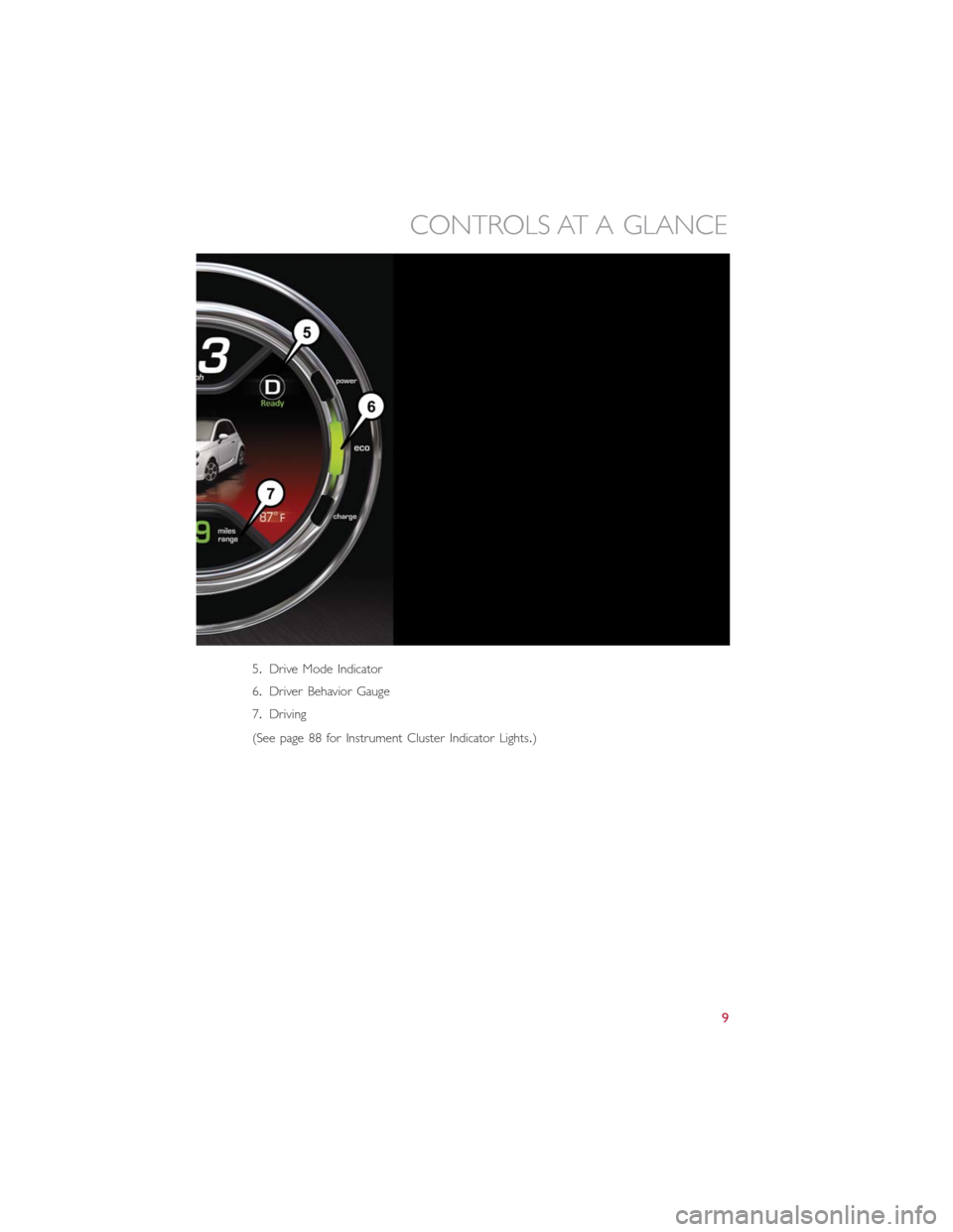
5.Drive Mode Indicator
6.Driver Behavior Gauge
7.Driving
(See page 88 for Instrument Cluster Indicator Lights.)
CONTROLS AT A GLANCE
9
Page 20 of 132
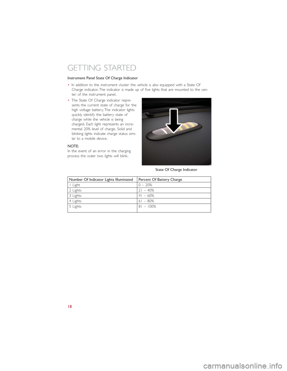
Instrument Panel State Of Charge Indicator
•In addition to the instrument cluster the vehicle is also equipped with a State Of
Charge indicator.The indicator is made up of five lights that are mounted to the cen-
ter of the instrument panel.
•The State Of Charge indicator repre-
sents the current state of charge for the
high voltage battery.The indicator lights
quickly identify the battery state of
charge while the vehicle is being
charged.Each light represents an incre-
mental 20% level of charge.Solid and
blinking lights indicate charge status simi-
lar to a mobile device.
NOTE:
In the event of an error in the charging
process the outer two lights will blink.
Number Of Indicator Lights Illuminated Percent Of Battery Charge
1 Light 0 – 20%
2 Lights 21 – 40%
3 Lights 41 – 60%
4 Lights 61 – 80%
5 Lights 81 – 100%
State Of Charge Indicator
GETTING STARTED
18
Page 23 of 132
VEHICLE SECURITY ALARM
The Vehicle Security Alarm monitors the vehicle doors for unauthorized entry and the
ignition for unauthorized operation.If something triggers the alarm, the Vehicle Security
Alarm will provide the following audible and visible signals: the horn will pulse, the park
lamps and/or turn signals will flash, and the Vehicle Security Light in the instrument cluster
will flash.
To Arm The System:
Push the Key Fob LOCK button.
To Disarm The System:
Push the Key Fob UNLOCK button or cycle the ignition to the ON/RUN position.
The Vehicle Security Alarm is designed to protect your vehicle.However, you can create
conditions where the Vehicle Security Alarm will give you a false alarm.If one of the pre-
viously described arming sequences has occurred, the Vehicle Security Alarm will arm re-
gardless of whether you are in the vehicle or not.If you remain in the vehicle and open
a door, the alarm will sound.If this occurs, disarm the Vehicle Security Alarm.
If the Vehicle Security Alarm is armed and the battery becomes disconnected, the Vehicle
Security Alarm will remain armed when the battery is reconnected.The exterior lights
will flash, and the horn will sound.If this occurs, disarm the Vehicle Security Alarm.
POWER DOOR LOCKS
The vehicles power door locks are activated by moving the inside door handles.
Push or pull the driver’s door handle to lock or unlock the doors and liftgate when the
doors are closed.
OCCUPANT RESTRAINT SYSTEMS
Some of the most important safety features in your vehicle are the restraint systems:
•Seat Belt Systems
•Supplemental Restraint Systems (SRS) Air Bags
•Child Restraints
GETTING STARTED
21
Page 27 of 132
WARNING!
•Side Air Bags need room to inflate.Do not lean against the door or window.Sit
upright in the center of the seat.
•Being too close to the Side Air Bags during deployment could cause you to be
severely injured or killed.
•Relying on the Side Air Bags alone could lead to more severe injuries in a collision.
The Side Air Bags work with your seat belt to restrain you properly.In some colli-
sions, Side Air Bags won’t deploy at all.Always wear your seat belt even though
you have Side Air Bags.
•This vehicle is equipped with left and right Supplemental Side Air Bag Inflatable
Curtains (SABICs).Do not stack luggage or other cargo up high enough to block
the deployment of the SABICs.The trim covering above the side windows where
the SABIC and its deployment path are located should remain free from any ob-
structions.
•This vehicle is equipped with SABICs.In order for the SABICs to work as in-
tended, do not install any accessory items in your vehicle which could alter the
roof.Do not add an aftermarket sunroof to your vehicle.Do not add roof racks
that require permanent attachments (bolts or screws) for installation on the ve-
hicle roof.Do not drill into the roof of the vehicle for any reason.
•Do not use accessory seat covers or place objects between you and the Side Air
Bags; the performance could be adversely affected and/or objects could be pushed
into you, causing serious injury.
Enhanced Accident Response System
In the event of an impact, if the communication network remains intact, and the power
remains intact, depending on the nature of the event, the ORC will determine whether
to have the Enhanced Accident Response System perform the following functions:
•Cut off battery power to the motor.
•Flash hazard lights as long as the battery has power or until the hazard light button is
pressed.The hazard lights can be deactivated by pressing the hazard light button.
•Turn on the interior lights, which remain on as long as the battery has power.
•Unlock the power door locks.
Enhanced Accident Response System Reset Procedure
After an event occurs requiring activation of the Enhanced Accident Response System,
when the system is active, a “Service EV System” message” will be displayed on the in-
strument cluster.The vehicle is not drivable in this state and must be towed to an autho-
rized dealer immediately to be inspected and have the Enhanced Accident Response Sys-
tem reset.
GETTING STARTED
25
Page 42 of 132
LIGHTS
MULTIFUNCTION LEVER
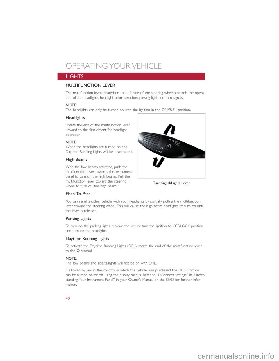
The multifunction lever, located on the left side of the steering wheel, controls the opera-
tion of the headlights, headlight beam selection, passing light and turn signals.
NOTE:
The headlights can only be turned on with the ignition in the ON/RUN position.
Headlights
Rotate the end of the multifunction lever
upward to the first detent for headlight
operation.
NOTE:
When the headlights are turned on, the
Daytime Running Lights will be deactivated.
High Beams
With the low beams activated, push the
multifunction lever towards the instrument
panel to turn on the high beams.Pull the
multifunction lever toward the steering
wheel to turn off the high beams.
Flash-To-Pass
You can signal another vehicle with your headlights by partially pulling the multifunction
lever toward the steering wheel.This will cause the high beam headlights to turn on until
the lever is released.
Parking Lights
To turn on the parking lights, remove the key or turn the ignition to OFF/LOCK position
and turn on the headlights.
Daytime Running Lights
To activate the Daytime Running Lights (DRL), rotate the end of the multifunction lever
to theOsymbol.
NOTE:
The low beams and side/taillights will not be on with DRL.
If allowed by law in the country in which the vehicle was purchased the DRL function
can be turned on or off using the display menus.Refer to “UConnect settings” in “Under-
standing Your Instrument Panel” in your Owner’s Manual on the DVD for further infor-
mation.
Turn Signal/Lights Lever
OPERATING YOUR VEHICLE
40
Page 43 of 132
Turn Signals
Push the multifunction lever upward to signal a right turn or downward to signal a left
turn.The corresponding indicator in the instrument cluster will blink to indicate the op-
eration of the turn signal.
NOTE:
The indicators will automatically turn off when the turn has been completed and the
steering wheel is returned to a straight position.
Lane Change Assist
Tap the lever up or down once, without moving beyond the detent, and the turn signal
(right or left) will flash three times then automatically turn off.
Follow Me Home/Headlight Delay
When this feature is selected the driver can choose to have the headlights remain on for
a preset period of time.
Activation
Remove the key or turn the ignition to the OFF/LOCK position, and pull the multifunc-
tion lever toward the steering wheel, within two minutes.Each time the lever is pulled,
the activation of the lights will be extended by 30 seconds.The activation of the lights
can be extended to a maximum of 210 seconds.
Deactivation
Pull the multifunction lever toward the steering wheel and hold it for more than two
seconds.
Interior Lights
The interior light switches are located in the overhead console.The interior lights can be
set to three different positions (Off/Left Position, Center Position, On/Right Position).
Using the switch on the left overhead, push the switch to the right from its center posi-
tion and the lights are always on.Push the switch to the left from its center position and
the lights are always off.Leave the switch in the center position, and the lights are turned
on and off when the doors are opened or closed.The switch on the right side of the
overhead console controls the map or reading function of the lights.Push the switch to
the right to turn on the right light and push the switch to the left to turn on the left
light.
CAUTION!
Before getting out of the vehicle be sure that the switch is in the center position or
that the lights are off to avoid draining the battery.
OPERATING YOUR VEHICLE
41