ignition FIAT 500E 2016 2.G Owner's Manual
[x] Cancel search | Manufacturer: FIAT, Model Year: 2016, Model line: 500E, Model: FIAT 500E 2016 2.GPages: 132, PDF Size: 4.59 MB
Page 103 of 132

In order to move your vehicle to the side of the road the transmission must be in NEU-
TRAL and the 12 Volt system must be functional.To place the transmission into NEU-
TRAL you must turn the ignition OFF and then back to the RUN position (cycle the igni-
tion) then push the NEUTRAL button.
NOTE:
The high voltage battery will remain disabled after an Enhanced Accident Response Event
and must be reset by your authorized dealership.
FREEING A STUCK VEHICLE
If your vehicle becomes stuck in mud, sand or snow, it can often be moved using a rock-
ing motion.Turn the steering wheel right and left to clear the area around the front
wheels.Then shift back and forth between DRIVE and REVERSE while gently pushing the
accelerator.Use the least amount of accelerator pedal pressure that will maintain the
rocking motion, without spinning the wheels.
NOTE:
Push the “ESC Off ” switch, to place the Electronic Stability Control (ESC) system in “Par-
tial Off ” mode, before rocking the vehicle.Refer to “Electronic Brake Control” in “Start-
ing And Operating” on the DVD for further information.Once the vehicle has been
freed, push the “ESC Off ” switch again to restore “ESC On” mode.
CAUTION!
•When “rocking” a stuck vehicle by shifting between DRIVE and REVERSE, do not
spin the wheels faster than 15 mph (24 km/h), or drivetrain damage may result.
•Spinning the wheels too fast may lead to transmission overheating and failure.It
can also damage the tires.Do not spin the wheels above 30 mph (48 km/h) while
in gear.
WARNING!
Fast spinning tires can be dangerous.Forces generated by excessive wheel speeds may
cause damage, or even failure, of the axle and tires.A tire could explode and injure
someone.Do not spin your vehicle's wheels faster than 30 mph (48 km/h) or for lon-
ger than 30 seconds continuously without stopping when you are stuck and do not let
anyone near a spinning wheel, no matter what the speed.
WHAT TO DO IN EMERGENCIES
101
Page 112 of 132

FUSES
WARNING!
•When replacing a blown fuse, always use an appropriate replacement fuse with
the same amp rating as the original fuse.Never replace a fuse with another fuse
of higher amp rating.Never replace a blown fuse with metal wires or any other
material.Failure to use proper fuses may result in serious personal injury, fire
and/or property damage.
•Before replacing a fuse, make sure that the ignition is off and that all the other
services are switched off and/or disengaged.
•If the replaced fuse blows again, contact an authorized dealer.
•If a general protection fuse for safety systems (air bag system, braking system),
power unit systems (engine system, gearbox system) or steering system blows,
contact an authorized dealer.
Interior Fuses
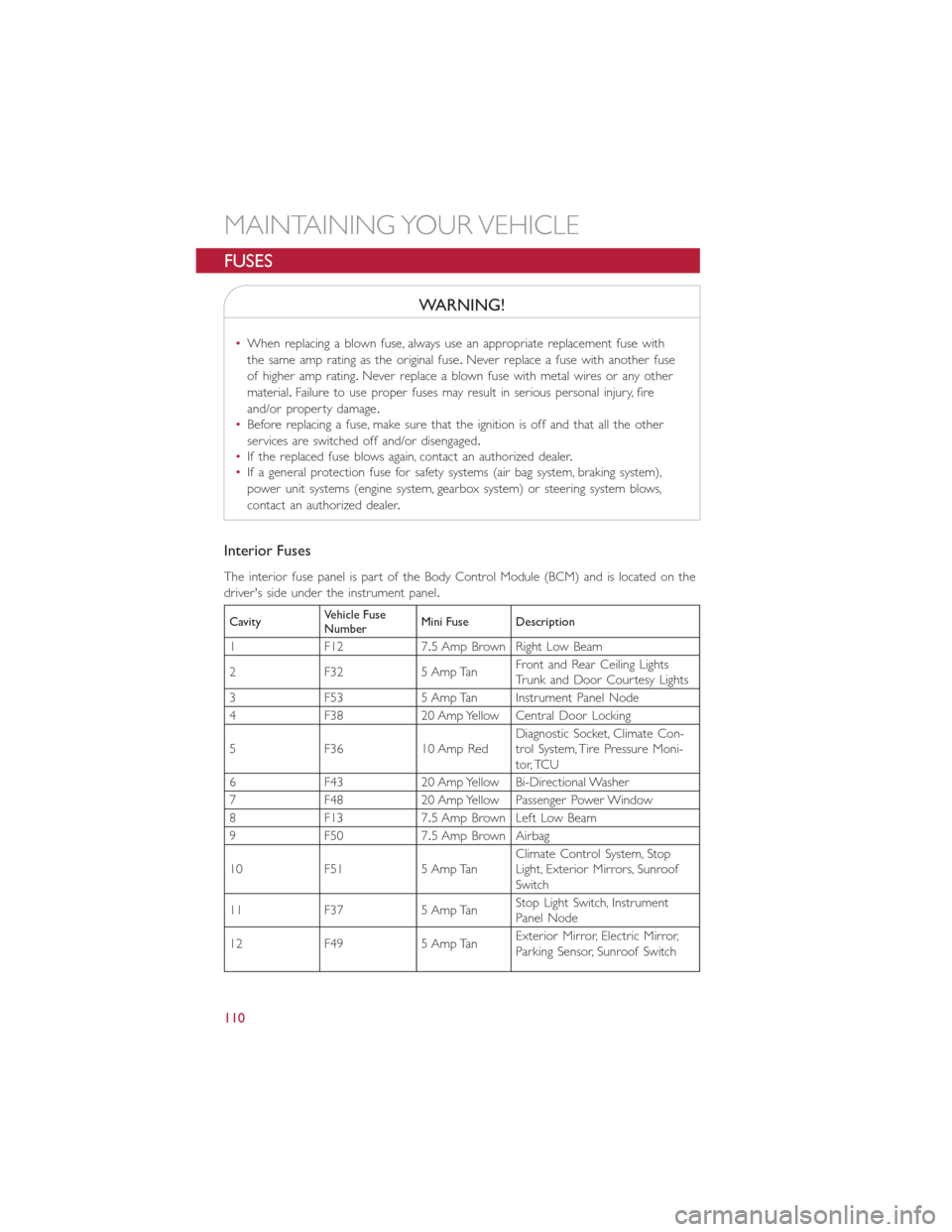
The interior fuse panel is part of the Body Control Module (BCM) and is located on the
driver's side under the instrument panel.
CavityVehicle Fuse
NumberMini Fuse Description
1 F12 7.5 Amp Brown Right Low Beam
2 F32 5 Amp TanFront and Rear Ceiling Lights
Trunk and Door Courtesy Lights
3 F53 5 Amp Tan Instrument Panel Node
4 F38 20 Amp Yellow Central Door Locking
5 F36 10 Amp RedDiagnostic Socket, Climate Con-
trol System, Tire Pressure Moni-
tor, TCU
6 F43 20 Amp Yellow Bi-Directional Washer
7 F48 20 Amp Yellow Passenger Power Window
8 F13 7.5 Amp Brown Left Low Beam
9 F50 7.5 Amp Brown Airbag
10 F51 5 Amp TanClimate Control System, Stop
Light, Exterior Mirrors, Sunroof
Switch
11 F37 5 Amp TanStop Light Switch, Instrument
Panel Node
12 F49 5 Amp TanExterior Mirror, Electric Mirror,
Parking Sensor, Sunroof Switch
MAINTAINING YOUR VEHICLE
110
Page 113 of 132

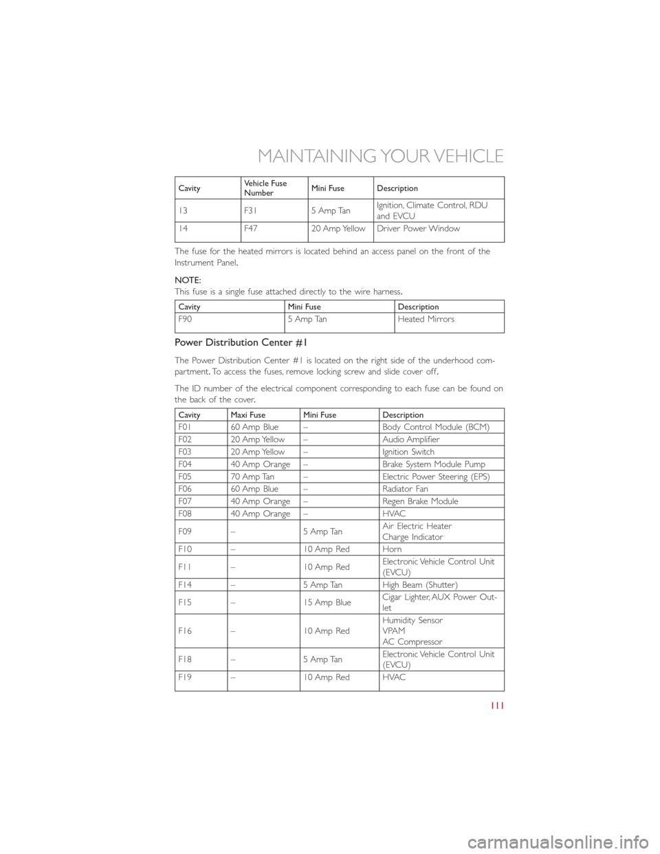
CavityVehicle Fuse
NumberMini Fuse Description
13 F31 5 Amp TanIgnition, Climate Control, RDU
and EVCU
14 F47 20 Amp Yellow Driver Power Window
The fuse for the heated mirrors is located behind an access panel on the front of the
Instrument Panel.
NOTE:
This fuse is a single fuse attached directly to the wire harness.
Cavity Mini Fuse Description
F90 5 Amp Tan Heated Mirrors
Power Distribution Center #1
The Power Distribution Center #1 is located on the right side of the underhood com-
partment.To access the fuses, remove locking screw and slide cover off.
The ID number of the electrical component corresponding to each fuse can be found on
thebackofthecover.
Cavity Maxi Fuse Mini Fuse Description
F01 60 Amp Blue – Body Control Module (BCM)
F02 20 Amp Yellow – Audio Amplifier
F03 20 Amp Yellow – Ignition Switch
F04 40 Amp Orange – Brake System Module Pump
F05 70 Amp Tan – Electric Power Steering (EPS)
F06 60 Amp Blue – Radiator Fan
F07 40 Amp Orange – Regen Brake Module
F08 40 Amp Orange – HVAC
F09 – 5 Amp TanAir Electric Heater
Charge Indicator
F10 – 10 Amp Red Horn
F11 – 10 Amp RedElectronic Vehicle Control Unit
(EVCU)
F14 – 5 Amp Tan High Beam (Shutter)
F15 – 15 Amp BlueCigar Lighter, AUX Power Out-
let
F16 – 10 Amp RedHumidity Sensor
VPAM
AC Compressor
F18 – 5 Amp TanElectronic Vehicle Control Unit
(EVCU)
F19 – 10 Amp Red HVAC
MAINTAINING YOUR VEHICLE
111