brake fluid FIAT 500E 2016 2.G User Guide
[x] Cancel search | Manufacturer: FIAT, Model Year: 2016, Model line: 500E, Model: FIAT 500E 2016 2.GPages: 132, PDF Size: 4.59 MB
Page 22 of 132
KEY FOB
Locking And Unlocking The Doors
And Liftgate
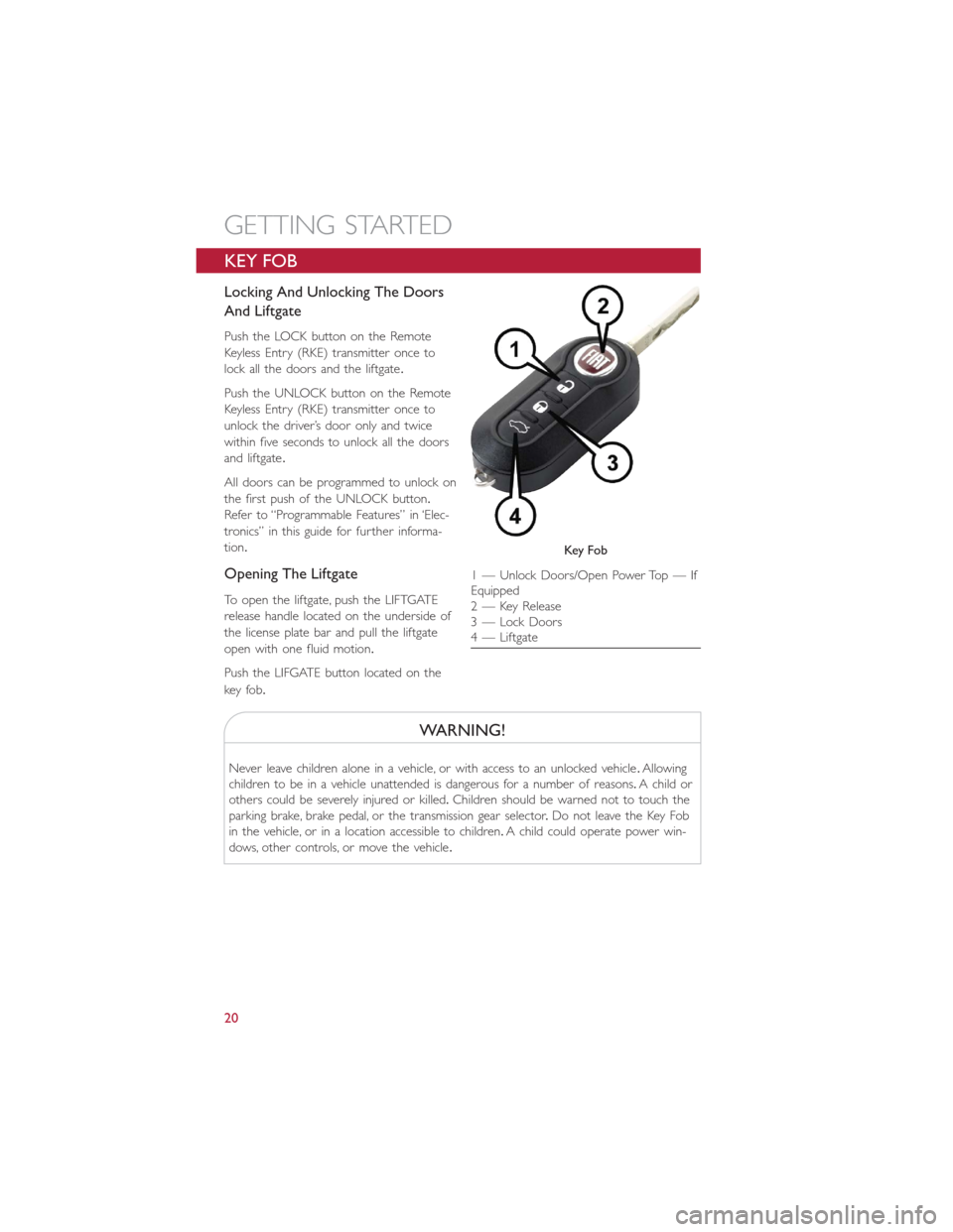
Push the LOCK button on the Remote
Keyless Entry (RKE) transmitter once to
lock all the doors and the liftgate.
Push the UNLOCK button on the Remote
Keyless Entry (RKE) transmitter once to
unlock the driver’s door only and twice
within five seconds to unlock all the doors
and liftgate.
All doors can be programmed to unlock on
the first push of the UNLOCK button.
Refer to “Programmable Features” in ‘Elec-
tronics” in this guide for further informa-
tion.
Opening The Liftgate
To open the liftgate, push the LIFTGATE
release handle located on the underside of
the license plate bar and pull the liftgate
open with one fluid motion.
Push the LIFGATE button located on the
key fob.
WARNING!
Never leave children alone in a vehicle, or with access to an unlocked vehicle.Allowing
children to be in a vehicle unattended is dangerous for a number of reasons.A child or
others could be severely injured or killed.Children should be warned not to touch the
parking brake, brake pedal, or the transmission gear selector.Do not leave the Key Fob
in the vehicle, or in a location accessible to children.A child could operate power win-
dows, other controls, or move the vehicle.
Key Fo b
1 — Unlock Doors/Open Power Top — If
Equipped
2 — Key Release
3 — Lock Doors
4 — Liftgate
GETTING STARTED
20
Page 87 of 132
– Brake Warning Light
This light monitors various brake functions, including brake fluid level and parking brake
application.If the brake light turns on, it may indicate that the parking brake is applied,
that the brake fluid level is low, or that there is a problem with the brake system master
cylinder reservoir.
If the light remains on when the parking brake has been disengaged, and the fluid level is
at the full mark on the master cylinder reservoir, it indicates a possible brake hydraulic
system malfunction or that a problem with the Brake Booster has been detected by the
Anti-Lock Brake System (ABS)/Electronic Stability Control (ESC) system.In this case, the
light will remain on until the condition has been corrected.If the problem is related to
the brake booster, the ABS pump will run when applying the brake, and a brake pedal
pulsation may be felt during each stop.
The dual brake system provides a reserve braking capacity in the event of a failure to a
portion of the hydraulic system.A leak in either half of the dual brake system is indicated
by the Brake Warning Light, which will turn on when the brake fluid level in the master
cylinder has dropped below a specified level.The light will remain on until the cause is
corrected.
Vehicles equipped with the Anti-Lock Brake System (ABS) are also equipped with Elec-
tronic Brake Force Distribution (EBD).In the event of an EBD failure, the Brake Warning
Light will turn on along with the ABS Light.Immediate repair to the ABS system is re-
quired.
Operation of the Brake Warning Light can be checked by turning the ignition switch from
the OFF position to the ON/RUN position.The light should illuminate for approximately
two seconds.The light should then turn off unless the parking brake is applied or a brake
fault is detected.If the light does not illuminate, have the light inspected by an authorized
dealer.
The light also will turn on when the parking brake is applied with the ignition switch in
the ON/RUN position.
NOTE:
This light shows only that the parking brake is applied.It does not show the degree of
brake application.
WARNING!
Driving a vehicle with the red brake light on is dangerous.Part of the brake system
may have failed.It will take longer to stop the vehicle.You could have a collision.Have
the vehicle checked immediately.
WHAT TO DO IN EMERGENCIES
85
Page 94 of 132
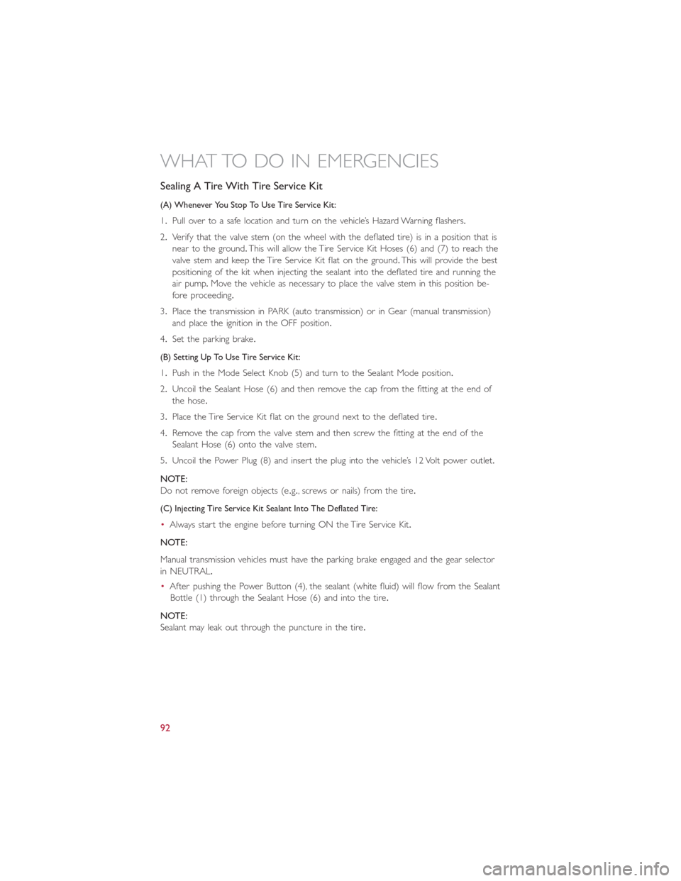
Sealing A Tire With Tire Service Kit
(A) Whenever You Stop To Use Tire Service Kit:
1.Pull over to a safe location and turn on the vehicle’s Hazard Warning flashers.
2.Verify that the valve stem (on the wheel with the deflated tire) is in a position that is
near to the ground.This will allow the Tire Service Kit Hoses (6) and (7) to reach the
valve stem and keep the Tire Service Kit flat on the ground.This will provide the best
positioning of the kit when injecting the sealant into the deflated tire and running the
air pump.Move the vehicle as necessary to place the valve stem in this position be-
fore proceeding.
3.Place the transmission in PARK (auto transmission) or in Gear (manual transmission)
and place the ignition in the OFF position.
4.Set the parking brake.
(B) Setting Up To Use Tire Service Kit:
1.Push in the Mode Select Knob (5) and turn to the Sealant Mode position.
2.Uncoil the Sealant Hose (6) and then remove the cap from the fitting at the end of
the hose.
3.Place the Tire Service Kit flat on the ground next to the deflated tire.
4.Remove the cap from the valve stem and then screw the fitting at the end of the
Sealant Hose (6) onto the valve stem.
5.Uncoil the Power Plug (8) and insert the plug into the vehicle’s 12 Volt power outlet.
NOTE:
Do not remove foreign objects (e.g., screws or nails) from the tire.
(C) Injecting Tire Service Kit Sealant Into The Deflated Tire:
•Always start the engine before turning ON the Tire Service Kit.
NOTE:
Manual transmission vehicles must have the parking brake engaged and the gear selector
in NEUTRAL.
•After pushing the Power Button (4), the sealant (white fluid) will flow from the Sealant
Bottle (1) through the Sealant Hose (6) and into the tire.
NOTE:
Sealant may leak out through the puncture in the tire.
WHAT TO DO IN EMERGENCIES
92
Page 106 of 132
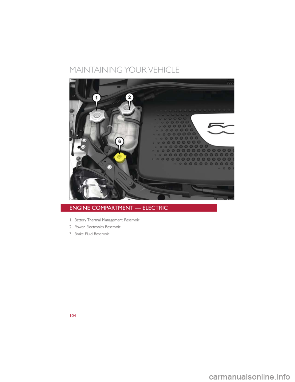
ENGINE COMPARTMENT — ELECTRIC
1.Battery Thermal Management Reservoir
2.Power Electronics Reservoir
3.Brake Fluid Reservoir
MAINTAINING YOUR VEHICLE
104
Page 108 of 132
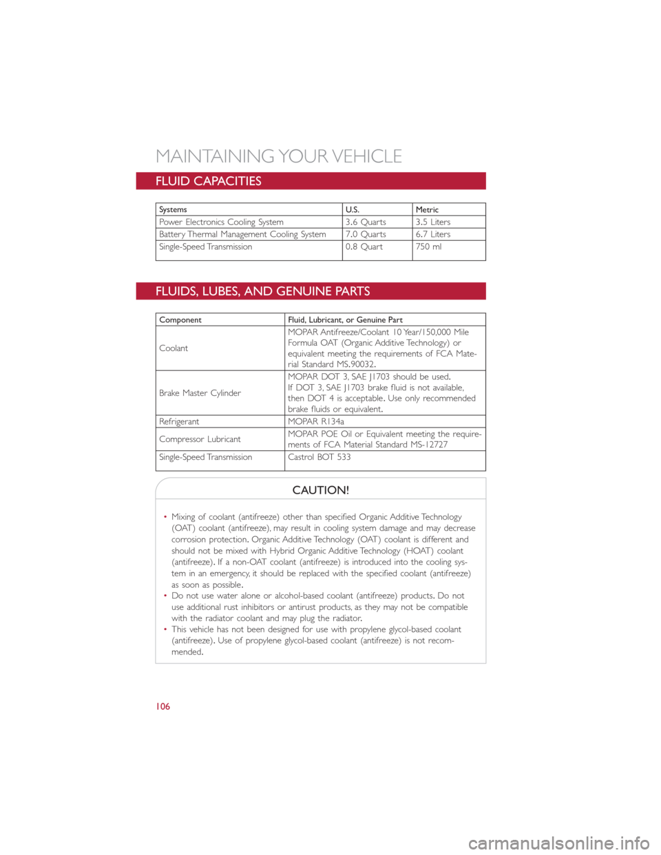
FLUID CAPACITIES
Systems
U.S. Metric
Power Electronics Cooling System 3.6 Quarts 3.5 Liters
Battery Thermal Management Cooling System 7.0 Quarts 6.7 Liters
Single-Speed Transmission 0.8 Quart 750 ml
FLUIDS, LUBES, AND GENUINE PARTS
Component Fluid, Lubricant, or Genuine Part
CoolantMOPAR Antifreeze/Coolant 10 Year/150,000 Mile
Formula OAT (Organic Additive Technology) or
equivalent meeting the requirements of FCA Mate-
rial Standard MS.90032.
Brake Master CylinderMOPAR DOT 3, SAE J1703 should be used.
If DOT 3, SAE J1703 brake fluid is not available,
then DOT 4 is acceptable.Use only recommended
brake fluids or equivalent.
Refrigerant MOPAR R134a
Compressor LubricantMOPAR POE Oil or Equivalent meeting the require-
ments of FCA Material Standard MS-12727
Single-Speed Transmission Castrol BOT 533
CAUTION!
•Mixing of coolant (antifreeze) other than specified Organic Additive Technology
(OAT) coolant (antifreeze), may result in cooling system damage and may decrease
corrosion protection.Organic Additive Technology (OAT) coolant is different and
should not be mixed with Hybrid Organic Additive Technology (HOAT) coolant
(antifreeze).If a non-OAT coolant (antifreeze) is introduced into the cooling sys-
tem in an emergency, it should be replaced with the specified coolant (antifreeze)
as soon as possible.
•Do not use water alone or alcohol-based coolant (antifreeze) products.Do not
use additional rust inhibitors or antirust products, as they may not be compatible
with the radiator coolant and may plug the radiator.
•This vehicle has not been designed for use with propylene glycol-based coolant
(antifreeze).Use of propylene glycol-based coolant (antifreeze) is not recom-
mended.
MAINTAINING YOUR VEHICLE
106
Page 109 of 132
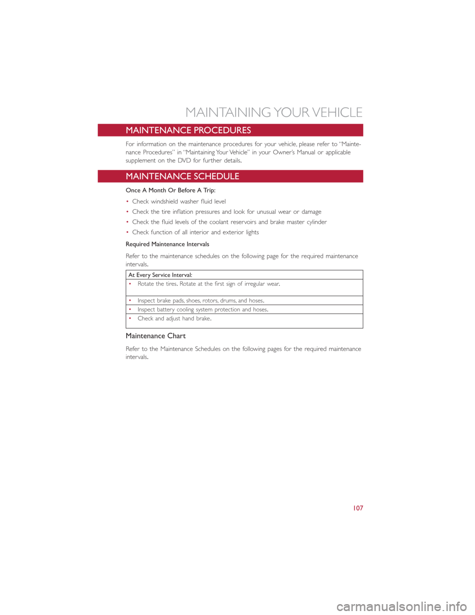
MAINTENANCE PROCEDURES
For information on the maintenance procedures for your vehicle, please refer to “Mainte-
nance Procedures” in “Maintaining Your Vehicle” in your Owner’s Manual or applicable
supplement on the DVD for further details.
MAINTENANCE SCHEDULE
Once A Month Or Before A Trip:
•Check windshield washer fluid level
•Check the tire inflation pressures and look for unusual wear or damage
•Check the fluid levels of the coolant reservoirs and brake master cylinder
•Check function of all interior and exterior lights
Required Maintenance Intervals
Refer to the maintenance schedules on the following page for the required maintenance
intervals.
At Every Service Interval:
•Rotate the tires.Rotate at the first sign of irregular wear.
•
Inspect brake pads, shoes, rotors, drums, and hoses.
•
Inspect battery cooling system protection and hoses.
•
Check and adjust hand brake.
Maintenance Chart
Refer to the Maintenance Schedules on the following pages for the required maintenance
intervals.
MAINTAINING YOUR VEHICLE
107
Page 123 of 132
Adding Washer Fluid............107
Air Bag
Advanced Front Air Bag.........23
Advance Front Air Bag.........23
Air Bags.................23
Air Bag Warning Light........23, 26
Driver Knee Air Bag...........24
Enhanced Accident Response......25
Event Data Recorder (EDR)......26
Front Air Bag..............23
Passenger Knee Air Bag.........24
Rollover.................23
Side Impacts...............23
Air Bag Light...............26, 84
Air Conditioner Maintenance.......107
Air Conditioning Refrigerant........107
Air Conditioning System..........107
Alarm
Disarm The System...........21
Vehicle Security Alarm.........21
Alarm (Security Alarm).........21, 88
Anti-Lock Warning Light...........84
Appearance Care.............107
Audio Systems (Radio)...........58
Automatic Temperature Control (ATC)...48
Battery...................107
Body Mechanism Lubrication........107
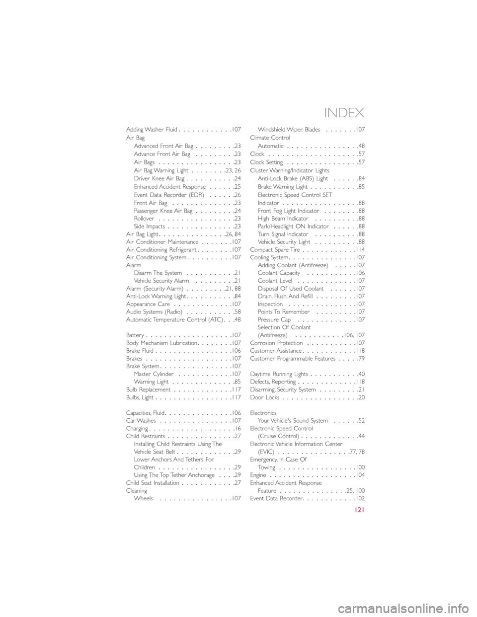
Brake Fluid.................106
Brakes...................107
Brake System................107
Master Cylinder............107
Warning Light..............85
Bulb Replacement.............117
Bulbs, Light.................117
Capacities, Fluid...............106
Car Washes................107
Charging...................16
Child Restraints...............27
Installing Child Restraints Using The
Vehicle Seat Belt.............29
Lower Anchors And Tethers For
Children.................29
Using The Top Tether Anchorage....29
Child Seat Installation............27
Cleaning
Wheels................107Windshield Wiper Blades.......107
Climate Control
Automatic................48
Clock....................57
Clock Setting................57
Cluster Warning/Indicator Lights
Anti-Lock Brake (ABS) Light......84
Brake Warning Light...........85
Electronic Speed Control SET
Indicator.................88
Front Fog Light Indicator........88
High Beam Indicator..........88
Park/Headlight ON Indicator......88
Turn Signal Indicator..........88
Vehicle Security Light..........88
Compact Spare Tire............114
Cooling System...............107
Adding Coolant (Antifreeze).....107
Coolant Capacity...........106
Coolant Level.............107
Disposal Of Used Coolant......107
Drain, Flush, And Refill.........107
Inspection...............107
Points To Remember.........107
Pressure Cap.............107
Selection Of Coolant
(Antifreeze)...........106, 107
Corrosion Protection...........107
Customer Assistance............
118
Customer Programmable Features.....79
Daytime Running Lights...........40
Defects, Reporting.............118
Disarming, Security System.........21
Door Locks.................20
Electronics
Your Vehicle's Sound System......52
Electronic Speed Control
(Cruise Control).............44
Electronic Vehicle Information Center
(EVIC)................77, 78
Emergency, In Case Of
Towing.................100
Engine...................104
Enhanced Accident Response
Feature...............25, 100
Event Data Recorder............102
INDEX
121
Page 124 of 132
Extending Driving Range..........39
FAQ....................120
Flashers
Turn Signal...............88
Fluids, Lubricants And Genuine Parts...106
Fog Lights................42, 88
Freeing A Stuck Vehicle...........101
Fuses....................110
General Maintenance............107
Glass Cleaning...............107
Hands-Free Phone (Uconnect).......68
Headlights..................40
Cleaning................107
Passing.................40
Switch..................40
Heated Mirrors...............49
Heated Seats................36
High Beam Indicator.............88
High Voltage Battery.............16
Hood Release...............103
Identifying Your Radio............55
Installing A Child Restraint With ALR....29
Installing Child Restraints Using The LATCH
Lower Anchorages............29
Instrument Cluster
Indicators.................8
Instrument Cluster Warning Lights.....83
Instrument Panel Cover..........107
Instrument Panel Lens Cleaning......107
Interior And Instrument Lights.......6, 7
Interior Appearance Care.........107
Interior Lighting...............41
iPod/USB/MP3 Control
Bluetooth Streaming Audio.......68
Key Fo b...................20
Disarm The Alarm............21
Lane Change Assist
.............41
Lap/Shoulder Belts..............22
LATCH (Lower Anchors And Tether For
CHildren)...............28, 30
Level 1 Charging...............13
Level 2 Charging...............13Liftgate....................20
Light Bulbs.................117
Lights....................40
Air Bag.................26
Fog...................88
High Beam...............40
High Beam Indicator..........88
Park...................40
Passing.................40
Seat Belt Reminder...........84
Security Alarm.............88
Turn Signal...............41
Locks
Key s...................20
Liftgate, Tailgate.............20
Lower Anchors And Tether For CHildren
(LATCH).................28
Lubrication, Body..............107
Maintenance Free Battery.........107
Maintenance, General...........107
Maintenance Procedures..........107
Maintenance Record............109
Maintenance Schedule...........107
Master Cylinder (Brakes)..........107
Mirrors
Heated.................49
MOPAR Accessories............119
Multi-Function Control Lever........40
Outlet
Power..................80
Paint Care.................107
Passing Light
.................40
Phone, Hands-Free (Uconnect).......68
Phone (Pairing)...............69
Phone (Uconnect)..............68
Placard, Tire And Loading Information...113
Power
Door Locks...............21
Outlet (Auxiliary Electrical Outlet)...80
Steering.................84
Sunroof.................50
Programmable Electronic Features.....78
Radio
Presets..................58
INDEX
122