engine FIAT 500E 2016 2.G User Guide
[x] Cancel search | Manufacturer: FIAT, Model Year: 2016, Model line: 500E, Model: FIAT 500E 2016 2.GPages: 132, PDF Size: 4.59 MB
Page 3 of 132
INTRODUCTION/WELCOMEWELCOME FROM FIAT...............2
IMPORTANT VEHICLE INFORMATION......4
CONTROLS AT A GLANCEDRIVER COCKPIT..................6
INSTRUMENT CLUSTER..............8
GETTING STARTEDELECTRIC VEHICLE FEATURES..........10
ELECTRIC SYSTEM OPERATION.........13
CHARGING THE HIGH VOLTAGE BATTERY...16
STARTING YOUR 500e...............19
KEY FOB......................20
VEHICLE SECURITY ALARM...........21
POWER DOOR LOCKS..............21
OCCUPANT RESTRAINT SYSTEMS........21
HEAD RESTRAINTS.................31
SEATS........................33
REAR SEATS.....................37
TILT STEERING COLUMN.............38
OPERATING YOUR VEHICLEEXTENDING YOUR DRIVING RANGE PER
CHARGE.......................39
LIGHTS.......................40
WIPER/WASHER LEVER..............43
ELECTRONIC SPEED CONTROL........44
POWER WINDOWS................47
AUTOMATIC TEMPERATURE CONTROLS
(ATC).........................48
REAR PARK ASSIST.................49
POWER SUNROOF.................50
ELECTRONICSYOUR VEHICLE'S SOUND SYSTEM........52
CYBERSECURITY..................54
IDENTIFYING YOUR RADIO............55
UCONNECT 5.0..................56
USB/AUX CONTROL................60
UCONNECT 5.0 VOICE RECOGNITION
QUICK TIPS.....................61
UCONNECT PHONE...............68
STEERING WHEEL AUDIO CONTROLS.....77
ELECTRONIC VEHICLE INFORMATION
CENTER (EVIC)...................77
PROGRAMMABLE FEATURES...........78
TRIP BUTTON....................79
POWER OUTLET.................80
UTILITY
TRAILER TOWING.................82
RECREATIONAL TOWING (BEHIND
MOTORHOME, ETC.)...............82
WHAT TO DO IN EMERGENCIES
ROADSIDE ASSISTANCE..............83
WARNING AND INDICATOR LIGHTS......83
TIRE SERVICE KIT..................89
JUMP-STARTING PROCEDURE
(12 VOLT BATTERY ONLY)............96
MANUAL PARK RELEASE.............99
TOWING A DISABLED VEHICLE.........100
ENHANCED ACCIDENT RESPONSE SYSTEM..100
FREEING A STUCK VEHICLE...........101
EVENT DATA RECORDER (EDR)........102
MAINTAINING YOUR VEHICLE
OPENING THE HOOD..............103
ENGINE COMPARTMENT — ELECTRIC....104
FLUID CAPACITIES................106
FLUIDS, LUBES, AND GENUINE PARTS.....106
MAINTENANCE PROCEDURES.........107
MAINTENANCE SCHEDULE..........107
FUSES.......................110
TIRES — GENERAL INFORMATION......113
TIRE ROTATION RECOMMENDATIONS....116
REPLACEMENT BULBS..............117
CUSTOMER ASSISTANCE
FIAT CUSTOMER CENTER............118
ASSISTANCE FOR THE HEARING
IMPAIRED.....................118
PUBLICATIONS ORDERING...........118
REPORTING SAFETY DEFECTS IN THE
UNITED STATES..................118
MOPAR® ACCESSORIES
AUTHENTIC ACCESSORIES BY MOPAR....119
FAQ ’s
FREQUENTLY ASKED QUESTIONS.......120
INDEX......................121
TABLE OF CONTENTS
1
Page 6 of 132
IMPORTANT VEHICLE INFORMATION
Your 500e operates entirely on electricity stored in the high voltage battery.Unlike a
conventional vehicle or Hybrid there is no internal combustion engine.Battery Electric
Vehicles have unique operating characteristics that you should become familiar with to
ensure you are getting the optimal performance from your vehicle.
High Voltage Battery
Your vehicle is equipped with a Lithium-ion high voltage battery that is used to power
the electric powertrain systems and the 12 Volt vehicle electrical system.
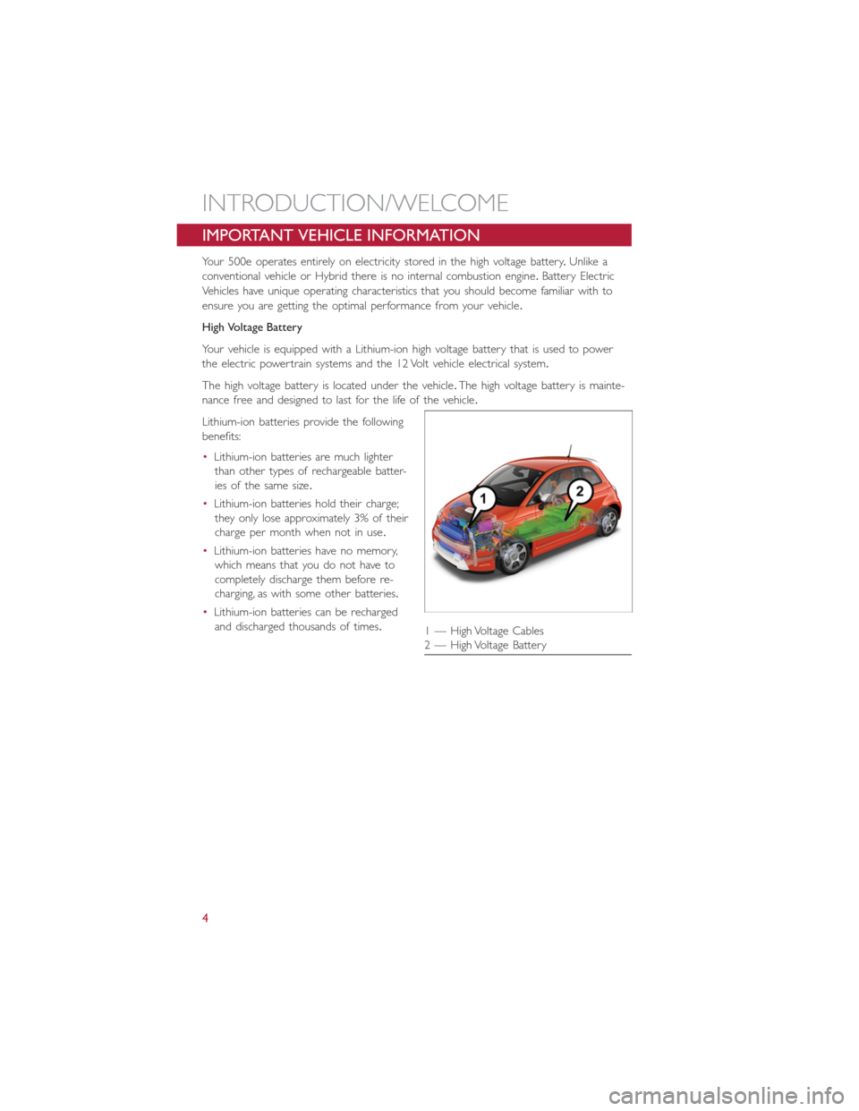
The high voltage battery is located under the vehicle.The high voltage battery is mainte-
nance free and designed to last for the life of the vehicle.
Lithium-ion batteries provide the following
benefits:
•Lithium-ion batteries are much lighter
than other types of rechargeable batter-
ies of the same size.
•Lithium-ion batteries hold their charge;
they only lose approximately 3% of their
charge per month when not in use.
•Lithium-ion batteries have no memory,
which means that you do not have to
completely discharge them before re-
charging, as with some other batteries.
•Lithium-ion batteries can be recharged
and discharged thousands of times.
1 — High Voltage Cables
2 — High Voltage Battery
INTRODUCTION/WELCOME
4
Page 28 of 132
Air Bag Warning Light
The air bags must be ready to inflate for your protection in a collision.The Occupant
Restraint Controller (ORC) monitors the internal circuits and interconnecting wiring asso-
ciated with air bag system electrical components.
The ORC monitors the readiness of the electronic parts of the air bag system whenever
the ignition switch is in the AVV or MAR position.If the ignition switch is in the STOP
position the air bag system is not on and the air bags will not inflate.
The ORC turns on the Air Bag Warning Light in the instrument panel for approximately
four to eight seconds for a self-check when the ignition switch is first turned to the MAR
position.After the self-check, the Air Bag Warning Light will turn off.If the ORC detects
a malfunction in any part of the system, it turns on the Air Bag Warning Light, either mo-
mentarily or continuously.A single chime will sound to alert you if the light comes on
again after initial startup.
If the Air Bag Warning Light in the instrument panel is not on during the four to eight
seconds when the ignition switch is first turned to the MAR position, stays on, or turns
on while driving, have the vehicle serviced by an authorized service center immediately.
NOTE:
If the speedometer, tachometer (if equipped), or any engine related gauges are not work-
ing, the Occupant Restraint Controller (ORC) may also be disabled.In this condition the
air bags may not be ready to inflate for your protection.Have an authorized dealer ser-
vice the air bag system immediately.
Event Data Recorder (EDR)
This vehicle is equipped with an event data recorder (EDR).The main purpose of an
EDR is to record, in certain crash or near crash-like situations, such as an air bag deploy-
ment or hitting a road obstacle, data that will assist in understanding how a vehicle’s sys-
tems performed.The EDR is designed to record data related to vehicle dynamics and
safety systems for a short period of time, typically 30 seconds or less.The EDR in this
vehicle is designed to record such data as:
•How various systems in your vehicle were operating;
•Whether or not the driver and passenger safety belts were buckled/fastened;
•How far (if at all) the driver was depressing the accelerator and/or brake pedal; and,
•How fast the vehicle was traveling.
GETTING STARTED
26
Page 81 of 132
Uconnect Customer Programmable Features
The Uconnect system allows you to access Customer Programmable feature settings.
To change a setting:
1.Push the SETTINGS
button located on the right side of the display.
2.Select a programmable feature you would like to adjust.
3.Make your selection highlighting the button.
Depending on the vehicles options, the following feature settings are available:
•Display•Audio
•Clock & Date•Phone/Bluetooth
•Safety/Assistance•SiriusXM Setup
•Lights•Voice
•Doors & Locks•Restore Settings
•Engine Off Options•Units
•Clear Personal Data•Charging Schedule
TRIP BUTTON
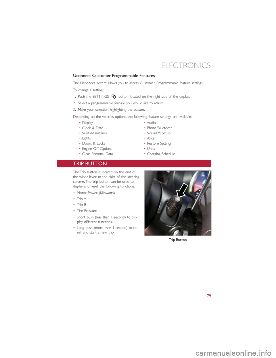
The Trip button is located on the end of
the wiper lever to the right of the steering
column.The trip button can be used to
display and reset the following functions:
•Motor Power (Kilowatts)
•Trip A
•Trip B
•Tire Pressure
•Short push (less than 1 second) to dis-
play different functions.
•Long push (more than 1 second) to re-
set and start a new trip.
Trip Button
ELECTRONICS
79
Page 89 of 132
NOTE:
Tire pressures change by approximately 1 psi (7 kPa) per 12° F (7° C) of air tempera-
ture change.Keep this in mind when checking tire pressure inside a garage, especially in
the Winter.Example: If garage temperature is 68°F (20°C) and the outside temperature
is 32°F (0°C), then the cold tire inflation pressure should be increased by 3 psi (21 kPa),
which equals 1 psi (7 kPa) for every 12°F (7°C) for this outside temperature condition.
CAUTION!
The TPMS has been optimized for the original equipment tires and wheels.TPMS pres-
sures and warning have been established for the tire size equipped on your vehicle.
Undesirable system operation or sensor damage may result when using replacement
equipment that is not of the same size, type, and/or style.Aftermarket wheels can cause
sensor damage.Do not use tire sealant from a can, or balance beads if your vehicle is
equipped with a TPMS, as damage to the sensors may result.
– Electronic Stability Control (ESC) Activation / Malfunction Indicator Light
The “ESC Activation/Malfunction Indicator Light” in the instrument cluster will come on
for four seconds when the ignition switch is turned to the ON/RUN position.If the “ESC
Activation/Malfunction Indicator Light” comes on continuously with the engine running, a
malfunction has been detected in the ESC system.If this light remains on, see your au-
thorized dealer as soon as possible to have the problem diagnosed and corrected.
NOTE:
•The “ESC Off Indicator Light” and the “ESC Activation/Malfunction Indicator Light”
come on momentarily each time the ignition switch is turned to ON/RUN.
•Each time the ignition is turned to ON/RUN, the ESC system will be ON even if it
was turned off previously.
•ESC Activation/Malfunction Light can blink during a ESC or TC intervention.
WHAT TO DO IN EMERGENCIES
87
Page 94 of 132
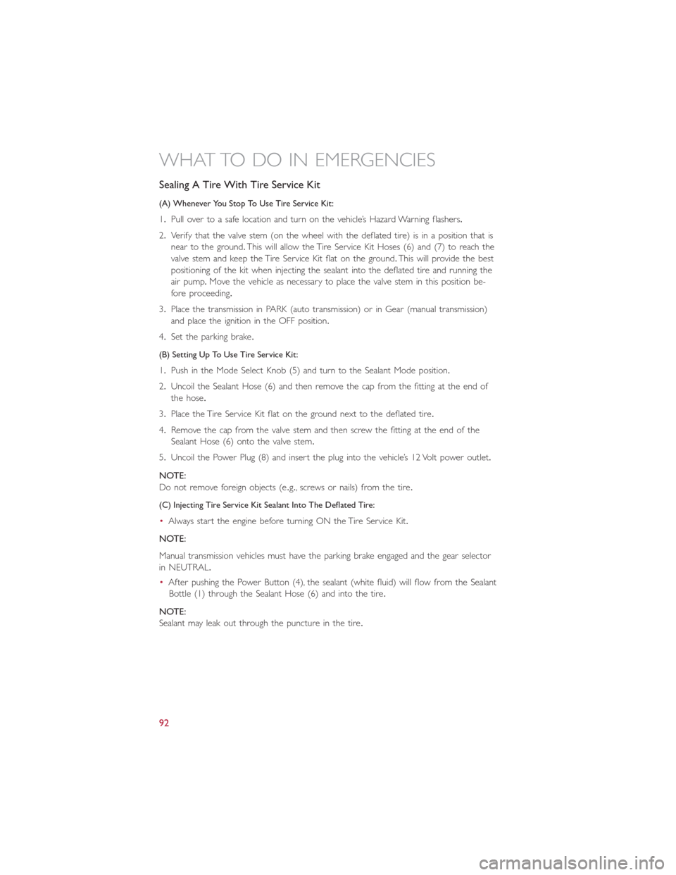
Sealing A Tire With Tire Service Kit
(A) Whenever You Stop To Use Tire Service Kit:
1.Pull over to a safe location and turn on the vehicle’s Hazard Warning flashers.
2.Verify that the valve stem (on the wheel with the deflated tire) is in a position that is
near to the ground.This will allow the Tire Service Kit Hoses (6) and (7) to reach the
valve stem and keep the Tire Service Kit flat on the ground.This will provide the best
positioning of the kit when injecting the sealant into the deflated tire and running the
air pump.Move the vehicle as necessary to place the valve stem in this position be-
fore proceeding.
3.Place the transmission in PARK (auto transmission) or in Gear (manual transmission)
and place the ignition in the OFF position.
4.Set the parking brake.
(B) Setting Up To Use Tire Service Kit:
1.Push in the Mode Select Knob (5) and turn to the Sealant Mode position.
2.Uncoil the Sealant Hose (6) and then remove the cap from the fitting at the end of
the hose.
3.Place the Tire Service Kit flat on the ground next to the deflated tire.
4.Remove the cap from the valve stem and then screw the fitting at the end of the
Sealant Hose (6) onto the valve stem.
5.Uncoil the Power Plug (8) and insert the plug into the vehicle’s 12 Volt power outlet.
NOTE:
Do not remove foreign objects (e.g., screws or nails) from the tire.
(C) Injecting Tire Service Kit Sealant Into The Deflated Tire:
•Always start the engine before turning ON the Tire Service Kit.
NOTE:
Manual transmission vehicles must have the parking brake engaged and the gear selector
in NEUTRAL.
•After pushing the Power Button (4), the sealant (white fluid) will flow from the Sealant
Bottle (1) through the Sealant Hose (6) and into the tire.
NOTE:
Sealant may leak out through the puncture in the tire.
WHAT TO DO IN EMERGENCIES
92
Page 95 of 132
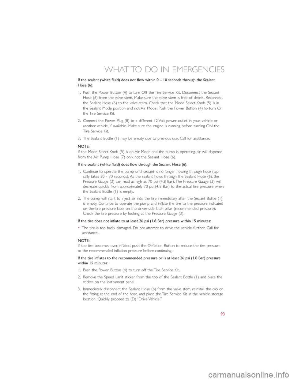
If the sealant (white fluid) does not flow within0–10seconds through the Sealant
Hose (6):
1.Push the Power Button (4) to turn Off the Tire Service Kit.Disconnect the Sealant
Hose (6) from the valve stem.Make sure the valve stem is free of debris.Reconnect
the Sealant Hose (6) to the valve stem.Check that the Mode Select Knob (5) is in
the Sealant Mode position and not Air Mode.Push the Power Button (4) to turn On
the Tire Service Kit.
2.Connect the Power Plug (8) to a different 12 Volt power outlet in your vehicle or
another vehicle, if available.Make sure the engine is running before turning ON the
Tire Service Kit.
3.The Sealant Bottle (1) may be empty due to previous use.Call for assistance.
NOTE:
If the Mode Select Knob (5) is on Air Mode and the pump is operating, air will dispense
from the Air Pump Hose (7) only, not the Sealant Hose (6).
If the sealant (white fluid) does flow through the Sealant Hose (6):
1.Continue to operate the pump until sealant is no longer flowing through hose (typi-
cally takes 30 - 70 seconds).As the sealant flows through the Sealant Hose (6), the
Pressure Gauge (3) can read as high as 70 psi (4.8 Bar).The Pressure Gauge (3) will
decrease quickly from approximately 70 psi (4.8 Bar) to the actual tire pressure when
the Sealant Bottle (1) is empty.
2.The pump will start to inject air into the tire immediately after the Sealant Bottle (1)
is empty.Continue to operate the pump and inflate the tire to the pressure indicated
on the tire pressure label on the driver-side latch pillar (recommended pressure).
Check the tire pressure by looking at the Pressure Gauge (3).
If the tire does not inflate to at least 26 psi (1.8 Bar) pressure within 15 minutes:
•The tire is too badly damaged.Do not attempt to drive the vehicle further.Call for
assistance.
NOTE:
If the tire becomes over-inflated, push the Deflation Button to reduce the tire pressure
to the recommended inflation pressure before continuing.
If the tire inflates to the recommended pressure or is at least 26 psi (1.8 Bar) pressure
within 15 minutes:
1.Push the Power Button (4) to turn off the Tire Service Kit.
2.Remove the Speed Limit sticker from the top of the Sealant Bottle (1) and place the
sticker on the instrument panel.
3.Immediately disconnect the Sealant Hose (6) from the valve stem, reinstall the cap on
the fitting at the end of the hose, and place the Tire Service Kit in the vehicle storage
location.Quickly proceed to (D) “Drive Vehicle.”
WHAT TO DO IN EMERGENCIES
93
Page 100 of 132
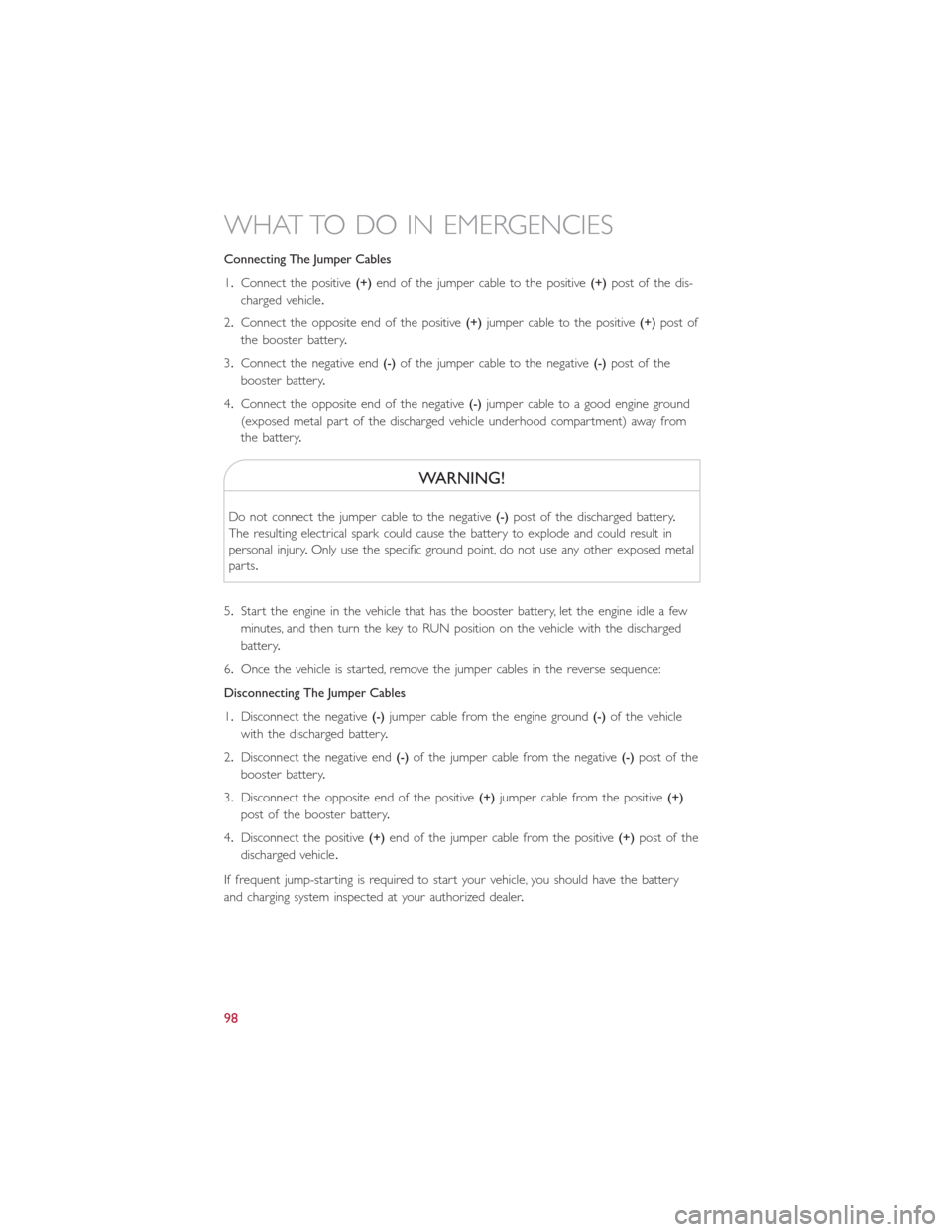
Connecting The Jumper Cables
1.Connect the positive(+)end of the jumper cable to the positive(+)post of the dis-
charged vehicle.
2.Connect the opposite end of the positive(+)jumper cable to the positive(+)post of
the booster battery.
3.Connect the negative end(-)of the jumper cable to the negative(-)post of the
booster battery.
4.Connect the opposite end of the negative(-)jumper cable to a good engine ground
(exposed metal part of the discharged vehicle underhood compartment) away from
the battery.
WARNING!
Do not connect the jumper cable to the negative(-)post of the discharged battery.
The resulting electrical spark could cause the battery to explode and could result in
personal injury.Only use the specific ground point, do not use any other exposed metal
parts.
5.Start the engine in the vehicle that has the booster battery, let the engine idle a few
minutes, and then turn the key to RUN position on the vehicle with the discharged
battery.
6.Once the vehicle is started, remove the jumper cables in the reverse sequence:
Disconnecting The Jumper Cables
1.Disconnect the negative(-)jumper cable from the engine ground(-)of the vehicle
with the discharged battery.
2.Disconnect the negative end(-)of the jumper cable from the negative(-)post of the
booster battery.
3.Disconnect the opposite end of the positive(+)jumper cable from the positive(+)
post of the booster battery.
4.Disconnect the positive(+)end of the jumper cable from the positive(+)post of the
discharged vehicle.
If frequent jump-starting is required to start your vehicle, you should have the battery
and charging system inspected at your authorized dealer.
WHAT TO DO IN EMERGENCIES
98
Page 105 of 132
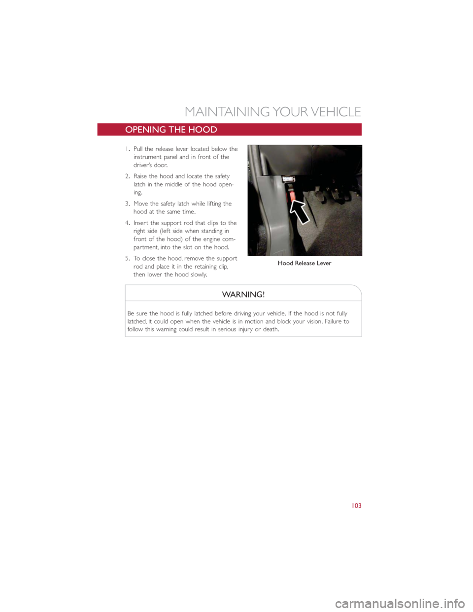
OPENING THE HOOD
1.Pull the release lever located below the
instrument panel and in front of the
driver’s door.
2.Raise the hood and locate the safety
latch in the middle of the hood open-
ing.
3.Move the safety latch while lifting the
hood at the same time.
4.Insert the support rod that clips to the
right side (left side when standing in
front of the hood) of the engine com-
partment, into the slot on the hood.
5.To close the hood, remove the support
rod and place it in the retaining clip,
then lower the hood slowly.
WARNING!
Be sure the hood is fully latched before driving your vehicle.If the hood is not fully
latched, it could open when the vehicle is in motion and block your vision.Failure to
follow this warning could result in serious injury or death.
Hood Release Lever
MAINTAINING YOUR VEHICLE
103
Page 106 of 132
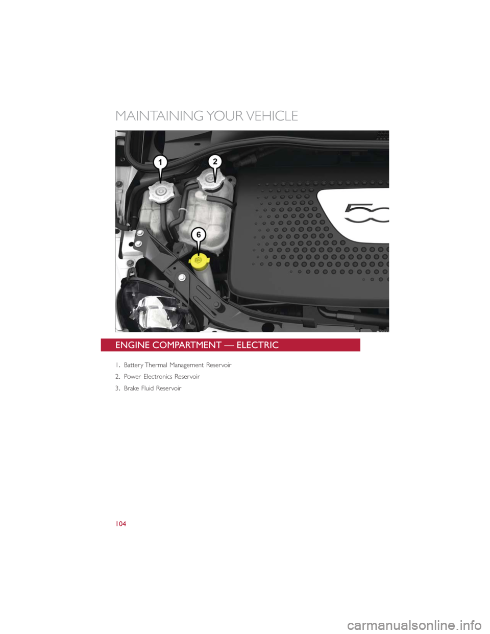
ENGINE COMPARTMENT — ELECTRIC
1.Battery Thermal Management Reservoir
2.Power Electronics Reservoir
3.Brake Fluid Reservoir
MAINTAINING YOUR VEHICLE
104