tow FIAT 500E 2016 2.G User Guide
[x] Cancel search | Manufacturer: FIAT, Model Year: 2016, Model line: 500E, Model: FIAT 500E 2016 2.GPages: 132, PDF Size: 4.59 MB
Page 3 of 132
INTRODUCTION/WELCOMEWELCOME FROM FIAT...............2
IMPORTANT VEHICLE INFORMATION......4
CONTROLS AT A GLANCEDRIVER COCKPIT..................6
INSTRUMENT CLUSTER..............8
GETTING STARTEDELECTRIC VEHICLE FEATURES..........10
ELECTRIC SYSTEM OPERATION.........13
CHARGING THE HIGH VOLTAGE BATTERY...16
STARTING YOUR 500e...............19
KEY FOB......................20
VEHICLE SECURITY ALARM...........21
POWER DOOR LOCKS..............21
OCCUPANT RESTRAINT SYSTEMS........21
HEAD RESTRAINTS.................31
SEATS........................33
REAR SEATS.....................37
TILT STEERING COLUMN.............38
OPERATING YOUR VEHICLEEXTENDING YOUR DRIVING RANGE PER
CHARGE.......................39
LIGHTS.......................40
WIPER/WASHER LEVER..............43
ELECTRONIC SPEED CONTROL........44
POWER WINDOWS................47
AUTOMATIC TEMPERATURE CONTROLS
(ATC).........................48
REAR PARK ASSIST.................49
POWER SUNROOF.................50
ELECTRONICSYOUR VEHICLE'S SOUND SYSTEM........52
CYBERSECURITY..................54
IDENTIFYING YOUR RADIO............55
UCONNECT 5.0..................56
USB/AUX CONTROL................60
UCONNECT 5.0 VOICE RECOGNITION
QUICK TIPS.....................61
UCONNECT PHONE...............68
STEERING WHEEL AUDIO CONTROLS.....77
ELECTRONIC VEHICLE INFORMATION
CENTER (EVIC)...................77
PROGRAMMABLE FEATURES...........78
TRIP BUTTON....................79
POWER OUTLET.................80
UTILITY
TRAILER TOWING.................82
RECREATIONAL TOWING (BEHIND
MOTORHOME, ETC.)...............82
WHAT TO DO IN EMERGENCIES
ROADSIDE ASSISTANCE..............83
WARNING AND INDICATOR LIGHTS......83
TIRE SERVICE KIT..................89
JUMP-STARTING PROCEDURE
(12 VOLT BATTERY ONLY)............96
MANUAL PARK RELEASE.............99
TOWING A DISABLED VEHICLE.........100
ENHANCED ACCIDENT RESPONSE SYSTEM..100
FREEING A STUCK VEHICLE...........101
EVENT DATA RECORDER (EDR)........102
MAINTAINING YOUR VEHICLE
OPENING THE HOOD..............103
ENGINE COMPARTMENT — ELECTRIC....104
FLUID CAPACITIES................106
FLUIDS, LUBES, AND GENUINE PARTS.....106
MAINTENANCE PROCEDURES.........107
MAINTENANCE SCHEDULE..........107
FUSES.......................110
TIRES — GENERAL INFORMATION......113
TIRE ROTATION RECOMMENDATIONS....116
REPLACEMENT BULBS..............117
CUSTOMER ASSISTANCE
FIAT CUSTOMER CENTER............118
ASSISTANCE FOR THE HEARING
IMPAIRED.....................118
PUBLICATIONS ORDERING...........118
REPORTING SAFETY DEFECTS IN THE
UNITED STATES..................118
MOPAR® ACCESSORIES
AUTHENTIC ACCESSORIES BY MOPAR....119
FAQ ’s
FREQUENTLY ASKED QUESTIONS.......120
INDEX......................121
TABLE OF CONTENTS
1
Page 27 of 132
WARNING!
•Side Air Bags need room to inflate.Do not lean against the door or window.Sit
upright in the center of the seat.
•Being too close to the Side Air Bags during deployment could cause you to be
severely injured or killed.
•Relying on the Side Air Bags alone could lead to more severe injuries in a collision.
The Side Air Bags work with your seat belt to restrain you properly.In some colli-
sions, Side Air Bags won’t deploy at all.Always wear your seat belt even though
you have Side Air Bags.
•This vehicle is equipped with left and right Supplemental Side Air Bag Inflatable
Curtains (SABICs).Do not stack luggage or other cargo up high enough to block
the deployment of the SABICs.The trim covering above the side windows where
the SABIC and its deployment path are located should remain free from any ob-
structions.
•This vehicle is equipped with SABICs.In order for the SABICs to work as in-
tended, do not install any accessory items in your vehicle which could alter the
roof.Do not add an aftermarket sunroof to your vehicle.Do not add roof racks
that require permanent attachments (bolts or screws) for installation on the ve-
hicle roof.Do not drill into the roof of the vehicle for any reason.
•Do not use accessory seat covers or place objects between you and the Side Air
Bags; the performance could be adversely affected and/or objects could be pushed
into you, causing serious injury.
Enhanced Accident Response System
In the event of an impact, if the communication network remains intact, and the power
remains intact, depending on the nature of the event, the ORC will determine whether
to have the Enhanced Accident Response System perform the following functions:
•Cut off battery power to the motor.
•Flash hazard lights as long as the battery has power or until the hazard light button is
pressed.The hazard lights can be deactivated by pressing the hazard light button.
•Turn on the interior lights, which remain on as long as the battery has power.
•Unlock the power door locks.
Enhanced Accident Response System Reset Procedure
After an event occurs requiring activation of the Enhanced Accident Response System,
when the system is active, a “Service EV System” message” will be displayed on the in-
strument cluster.The vehicle is not drivable in this state and must be towed to an autho-
rized dealer immediately to be inspected and have the Enhanced Accident Response Sys-
tem reset.
GETTING STARTED
25
Page 34 of 132
Reactive Head Restraints — Front Seats
The front driver and passenger seats are equipped with Reactive Head Restraints.In the
event of a rear impact the Reactive Head Restraints will automatically extend forward
minimizing the gap between the back of the occupant's head and the Reactive Head Re-
straint.
To raise the head restraint, pull upward on the head restraint.To lower the head re-
straint, push the adjustment button, located at the base of the head restraint, and push
downward on the head restraint.
The Reactive Head Restraints will automatically return to their normal position following a
rear impact.If the Reactive Head Restraints do not return to their normal position, see
your authorized dealership immediately.
NOTE:
The head restraints should only be removed by qualified technicians, for service purposes
only.If either of the head restraints require removal, see your authorized dealership.
WARNING!
•A loose head restraint thrown forward in a collision or hard stop could cause seri-
ous injury or death to occupants of the vehicle.Always securely stow removed
head restraints in a location outside the occupant compartment.
•ALL the head restraints MUST be reinstalled in the vehicle to properly protect
the occupants.Follow the re-installation instructions above prior to operating the
vehicle or occupying a seat.
•Do not place items over the top of the Reactive Head Restraint, such as coats,
seat covers or portable DVD players.These items may interfere with the opera-
tion of the Reactive Head Restraint in the event of a collision and could result in
serious injury or death.
Rear Head Restraints
To raise the head restraint, pull upward on the head restraint.To lower the head re-
straint, push the adjustment button, located at the base of the head restraint, and push
downward on the head restraint.Refer to “Occupant Restraints” in “Things To Know Be-
fore Starting Your Vehicle” in your Owner’s Manual on the DVD for further information
on tether routing.
NOTE:
To remove the head restraint, raise it as far as it can go then push the release button and
the adjustment button at the base of each post while pulling the head restraint up.To
reinstall the head restraint, put the head restraint posts into the holes and push down-
ward.Then adjust the head restraint to the appropriate height.
GETTING STARTED
32
Page 42 of 132
LIGHTS
MULTIFUNCTION LEVER
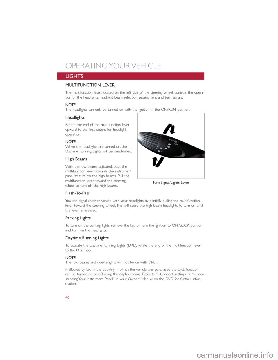
The multifunction lever, located on the left side of the steering wheel, controls the opera-
tion of the headlights, headlight beam selection, passing light and turn signals.
NOTE:
The headlights can only be turned on with the ignition in the ON/RUN position.
Headlights
Rotate the end of the multifunction lever
upward to the first detent for headlight
operation.
NOTE:
When the headlights are turned on, the
Daytime Running Lights will be deactivated.
High Beams
With the low beams activated, push the
multifunction lever towards the instrument
panel to turn on the high beams.Pull the
multifunction lever toward the steering
wheel to turn off the high beams.
Flash-To-Pass
You can signal another vehicle with your headlights by partially pulling the multifunction
lever toward the steering wheel.This will cause the high beam headlights to turn on until
the lever is released.
Parking Lights
To turn on the parking lights, remove the key or turn the ignition to OFF/LOCK position
and turn on the headlights.
Daytime Running Lights
To activate the Daytime Running Lights (DRL), rotate the end of the multifunction lever
to theOsymbol.
NOTE:
The low beams and side/taillights will not be on with DRL.
If allowed by law in the country in which the vehicle was purchased the DRL function
can be turned on or off using the display menus.Refer to “UConnect settings” in “Under-
standing Your Instrument Panel” in your Owner’s Manual on the DVD for further infor-
mation.
Turn Signal/Lights Lever
OPERATING YOUR VEHICLE
40
Page 43 of 132
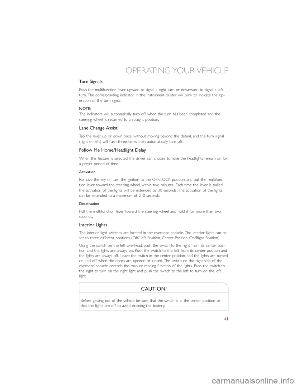
Turn Signals
Push the multifunction lever upward to signal a right turn or downward to signal a left
turn.The corresponding indicator in the instrument cluster will blink to indicate the op-
eration of the turn signal.
NOTE:
The indicators will automatically turn off when the turn has been completed and the
steering wheel is returned to a straight position.
Lane Change Assist
Tap the lever up or down once, without moving beyond the detent, and the turn signal
(right or left) will flash three times then automatically turn off.
Follow Me Home/Headlight Delay
When this feature is selected the driver can choose to have the headlights remain on for
a preset period of time.
Activation
Remove the key or turn the ignition to the OFF/LOCK position, and pull the multifunc-
tion lever toward the steering wheel, within two minutes.Each time the lever is pulled,
the activation of the lights will be extended by 30 seconds.The activation of the lights
can be extended to a maximum of 210 seconds.
Deactivation
Pull the multifunction lever toward the steering wheel and hold it for more than two
seconds.
Interior Lights
The interior light switches are located in the overhead console.The interior lights can be
set to three different positions (Off/Left Position, Center Position, On/Right Position).
Using the switch on the left overhead, push the switch to the right from its center posi-
tion and the lights are always on.Push the switch to the left from its center position and
the lights are always off.Leave the switch in the center position, and the lights are turned
on and off when the doors are opened or closed.The switch on the right side of the
overhead console controls the map or reading function of the lights.Push the switch to
the right to turn on the right light and push the switch to the left to turn on the left
light.
CAUTION!
Before getting out of the vehicle be sure that the switch is in the center position or
that the lights are off to avoid draining the battery.
OPERATING YOUR VEHICLE
41
Page 45 of 132
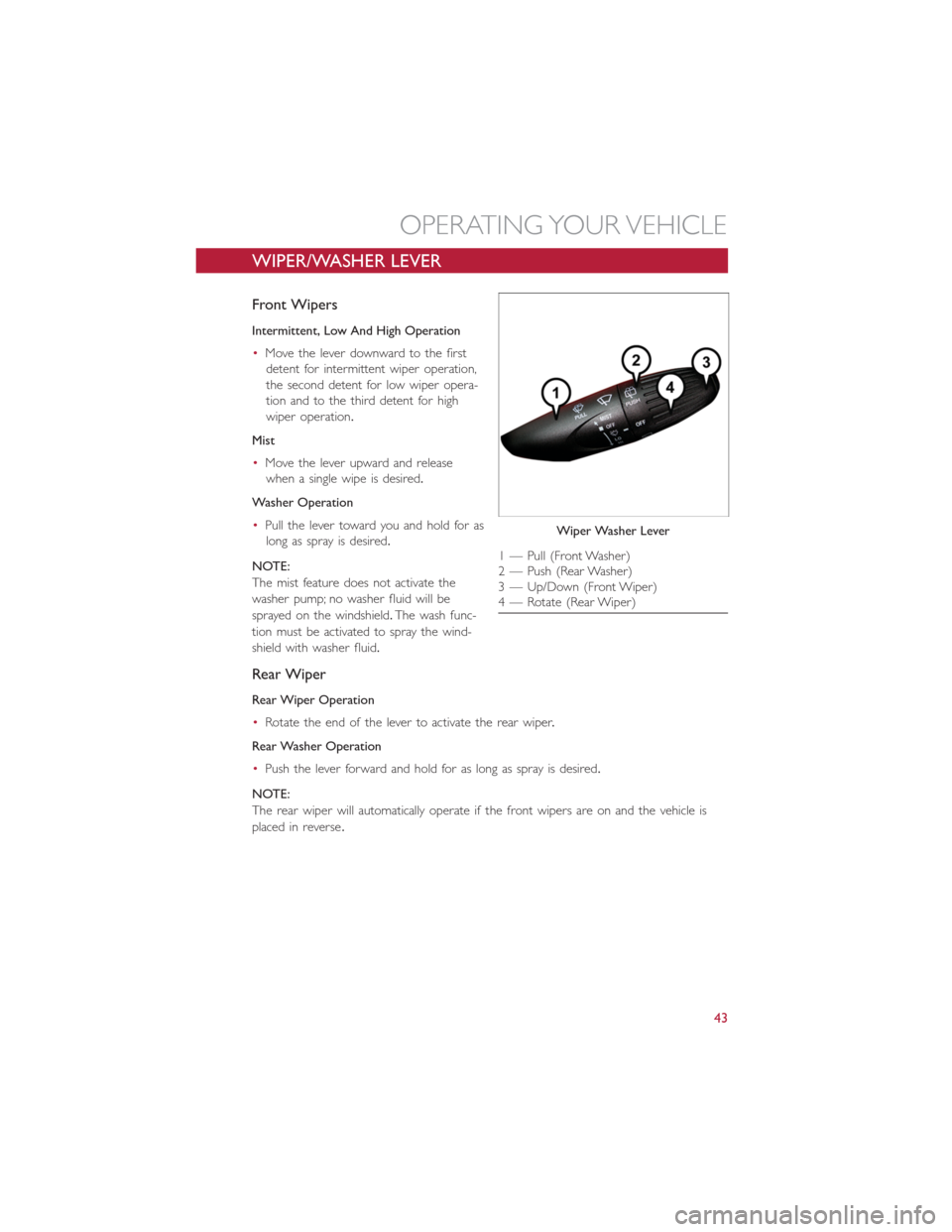
WIPER/WASHER LEVER
Front Wipers
Intermittent, Low And High Operation
•Move the lever downward to the first
detent for intermittent wiper operation,
the second detent for low wiper opera-
tion and to the third detent for high
wiper operation.
Mist
•Move the lever upward and release
when a single wipe is desired.
Washer Operation
•Pull the lever toward you and hold for as
long as spray is desired.
NOTE:
The mist feature does not activate the
washer pump; no washer fluid will be
sprayed on the windshield.The wash func-
tion must be activated to spray the wind-
shield with washer fluid.
Rear Wiper
Rear Wiper Operation
•Rotate the end of the lever to activate the rear wiper.
Rear Washer Operation
•Push the lever forward and hold for as long as spray is desired.
NOTE:
The rear wiper will automatically operate if the front wipers are on and the vehicle is
placed in reverse.
Wiper Washer Lever
1 — Pull (Front Washer)
2 — Push (Rear Washer)
3 — Up/Down (Front Wiper)
4 — Rotate (Rear Wiper)
OPERATING YOUR VEHICLE
43
Page 84 of 132
TRAILER TOWING
Trailer towing with this vehicle is not recommended.
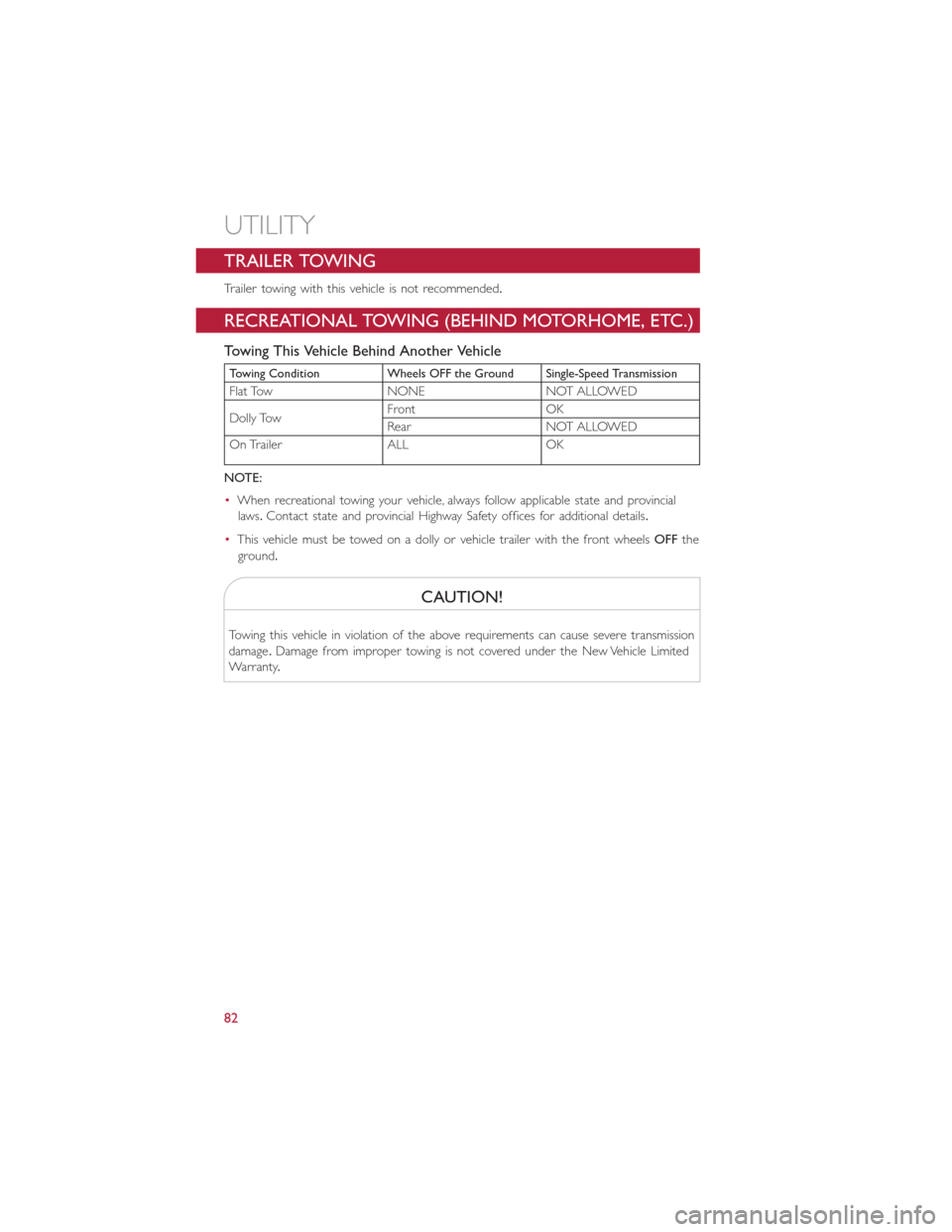
RECREATIONAL TOWING (BEHIND MOTORHOME, ETC.)
Towing This Vehicle Behind Another Vehicle
Towing Condition Wheels OFF the Ground Single-Speed Transmission
Flat Tow NONE NOT ALLOWED
Dolly TowFront OK
Rear NOT ALLOWED
On Trailer ALL OK
NOTE:
•When recreational towing your vehicle, always follow applicable state and provincial
laws.Contact state and provincial Highway Safety offices for additional details.
•This vehicle must be towed on a dolly or vehicle trailer with the front wheelsOFFthe
ground.
CAUTION!
Towing this vehicle in violation of the above requirements can cause severe transmission
damage.Damage from improper towing is not covered under the New Vehicle Limited
Warranty.
UTILITY
82
Page 85 of 132
ROADSIDE ASSISTANCE
•If your FIAT 500e requires jump start assistance, tire service, lockout service or towing
due to a defect covered under the Basic Limited Warranty, dial toll-free
1-888-242-6342.See your Warranty booklet for further details.
•Provide your name, vehicle identification number and license plate number.
•Provide your location, including telephone number, from which you are calling.
•Briefly describe the nature of the problem and answer a few simple questions.
•You will be given the name of the service provider and an estimated time of arrival.If
you feel you are in an “unsafe situation”, please let us know.With your consent, we will
contact local police or safety authorities.
WARNING AND INDICATOR LIGHTS
IMPORTANT:The warning / indicator lights switch on in the instrument panel together
with a dedicated message and/or acoustic signal when applicable.These indications are
indicative and precautionary and as such must not be considered as exhaustive and/or
alternative to the information contained in the Owner’s Manual, which you are advised to
read carefully in all cases.Always refer to the information in this chapter in the event of a
failure indication.
All active telltales will display first if applicable.The system check menu may appear differ-
ent based upon equipment options and current vehicle status.
This guide illustrates and describes the operation of warning and indicator telltales that
are either standard or optional based on the vehicle build.FCA reserves the right to
make changes in design and specifications and/or make additions to or improvements to
its products without imposing any obligation upon itself to install them on products previ-
ously manufactured.
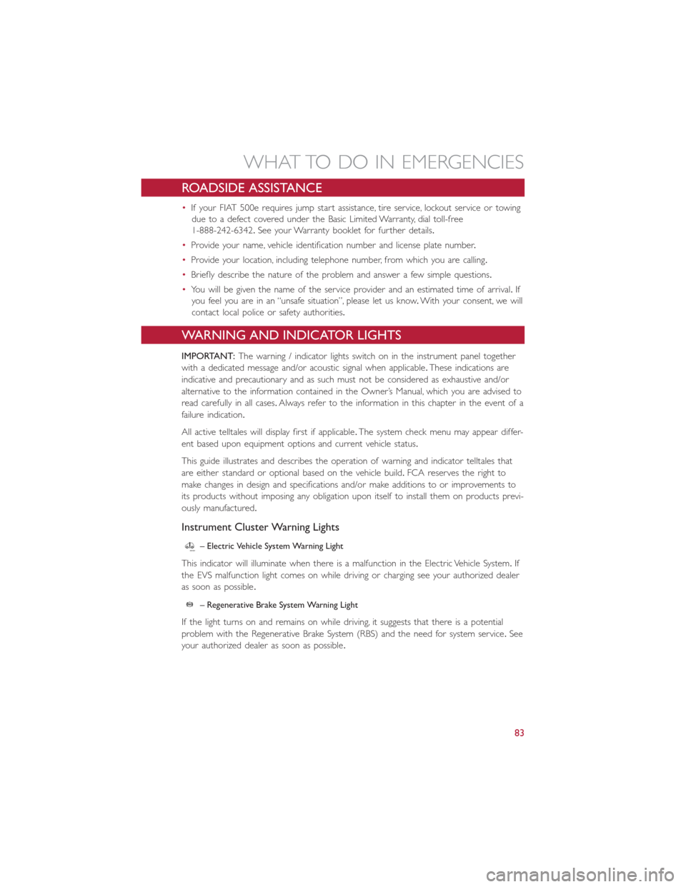
Instrument Cluster Warning Lights
– Electric Vehicle System Warning Light
This indicator will illuminate when there is a malfunction in the Electric Vehicle System.If
the EVS malfunction light comes on while driving or charging see your authorized dealer
as soon as possible.
– Regenerative Brake System Warning Light
If the light turns on and remains on while driving, it suggests that there is a potential
problem with the Regenerative Brake System (RBS) and the need for system service.See
your authorized dealer as soon as possible.
WHAT TO DO IN EMERGENCIES
83
Page 93 of 132
•For optimum performance, make sure the valve stem on the wheel is free of debris
before connecting the Tire Service Kit.
•You can use the Tire Service Kit air pump to inflate bicycle tires.The kit also comes
with two needles, located in the Accessory Storage Compartment (on the bottom of
the air pump) for inflating sport balls, rafts, or similar inflatable items.However, use
only the Air Pump Hose (7) and make sure the Mode Select Knob (5) is in the Air
Mode when inflating such items to avoid injecting sealant into them.The Tire Service
Kit Sealant is only intended to seal punctures less than 1/4 inch (6 mm) diameter in
the tread of your vehicle.
•Do not lift or carry the Tire Service Kit by the hoses.
WARNING!
•Do not attempt to seal a tire on the side of the vehicle closest to traffic.Pull far
enough off the road to avoid the danger of being hit when using the Tire Service
Kit.
•Do not use Tire Service Kit or drive the vehicle under the following circumstances:
•If the puncture in the tire tread is approximately 1/4 inch (6 mm) or larger.
•If the tire has any sidewall damage.
•If the tire has any damage from driving with extremely low tire pressure.
•If the tire has any damage from driving on a flat tire.
•If the wheel has any damage.
•If you are unsure of the condition of the tire or the wheel.
•Keep Tire Service Kit away from open flames or heat source.
•A loose Tire Service Kit thrown forward in a collision or hard stop could endanger
the occupants of the vehicle.Always stow the Tire Service Kit in the place pro-
vided.Failure to follow these warnings can result in injuries that are serious or
fatal to you, your passengers, and others around you.
•Take care not to allow the contents of Tire Service Kit to come in contact with
hair, eyes, or clothing.Tire Service Kit sealant is harmful if inhaled, swallowed, or
absorbed through the skin.It causes skin, eye, and respiratory irritation.Flush im-
mediately with plenty of water if there is any contact with eyes or skin.Change
clothing as soon as possible, if there is any contact with clothing.
•Tire Service Kit Sealant solution contains latex.In case of an allergic reaction or
rash, consult a physician immediately.Keep Tire Service Kit out of reach of chil-
dren.If swallowed, rinse mouth immediately with plenty of water and drink plenty
of water.Do not induce vomiting! Consult a physician immediately.
WHAT TO DO IN EMERGENCIES
91
Page 102 of 132
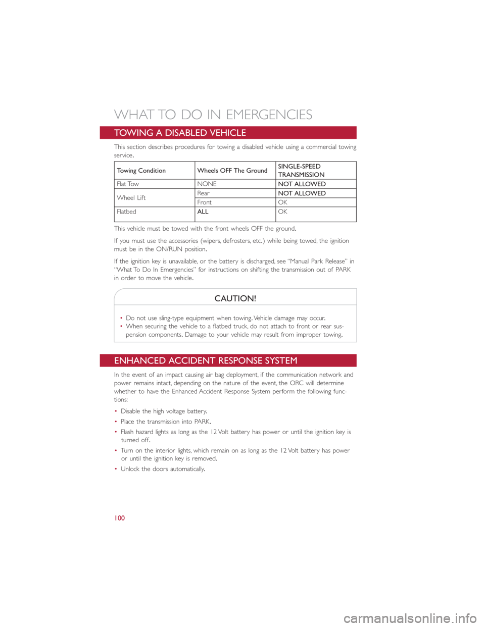
TOWING A DISABLED VEHICLE
This section describes procedures for towing a disabled vehicle using a commercial towing
service.
Towing Condition Wheels OFF The GroundSINGLE-SPEED
TRANSMISSION
Flat Tow NONE
NOT ALLOWED
Wheel LiftRear
NOT ALLOWED
Front OK
Flatbed
ALLOK
This vehicle must be towed with the front wheels OFF the ground.
If you must use the accessories (wipers, defrosters, etc.) while being towed, the ignition
must be in the ON/RUN position.
If the ignition key is unavailable, or the battery is discharged, see “Manual Park Release” in
“What To Do In Emergencies” for instructions on shifting the transmission out of PARK
in order to move the vehicle.
CAUTION!
•Do not use sling-type equipment when towing.Vehicle damage may occur.
•When securing the vehicle to a flatbed truck, do not attach to front or rear sus-
pension components.Damage to your vehicle may result from improper towing.
ENHANCED ACCIDENT RESPONSE SYSTEM
In the event of an impact causing air bag deployment, if the communication network and
power remains intact, depending on the nature of the event, the ORC will determine
whether to have the Enhanced Accident Response System perform the following func-
tions:
•Disable the high voltage battery.
•Place the transmission into PARK.
•Flash hazard lights as long as the 12 Volt battery has power or until the ignition key is
turned off.
•Turn on the interior lights, which remain on as long as the 12 Volt battery has power
or until the ignition key is removed.
•Unlock the doors automatically.
WHAT TO DO IN EMERGENCIES
100