FIAT 500E 2018 Owner's Guide
Manufacturer: FIAT, Model Year: 2018, Model line: 500E, Model: FIAT 500E 2018Pages: 302, PDF Size: 3.32 MB
Page 31 of 302
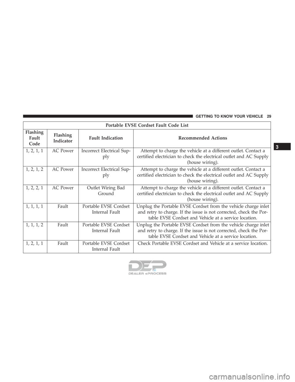
Portable EVSE Cordset Fault Code List
Flashing Fault
Code Flashing
Indicator Fault Indication Recommended Actions
1, 2, 1, 1 AC Power Incorrect Electrical Sup- plyAttempt to charge the vehicle at a different outlet. Contact a
certified electrician to check the electrical outlet and AC Supply (house wiring).
1, 2, 1, 2 AC Power Incorrect Electrical Sup- plyAttempt to charge the vehicle at a different outlet. Contact a
certified electrician to check the electrical outlet and AC Supply (house wiring).
1, 2, 2, 1 AC Power Outlet Wiring Bad GroundAttempt to charge the vehicle at a different outlet. Contact a
certified electrician to check the electrical outlet and AC Supply (house wiring).
1, 1, 1, 1 Fault Portable EVSE Cordset Internal FaultUnplug the Portable EVSE Cordset from the vehicle charge inlet
and retry to charge. If the issue is not corrected, check the Por- table EVSE Cordset and Vehicle at a service location.
1, 1, 1, 2 Fault Portable EVSE Cordset Internal FaultUnplug the Portable EVSE Cordset from the vehicle charge inlet
and retry to charge. If the issue is not corrected, check the Por- table EVSE Cordset and Vehicle at a service location.
1, 2, 1, 1 Fault Portable EVSE Cordset Internal FaultCheck Portable EVSE Cordset and Vehicle at a service location.
3
GETTING TO KNOW YOUR VEHICLE 29
Page 32 of 302
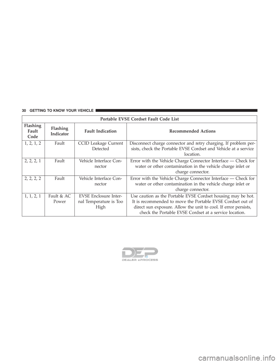
Portable EVSE Cordset Fault Code List
Flashing Fault
Code Flashing
Indicator Fault Indication Recommended Actions
1, 2, 1, 2 Fault CCID Leakage Current DetectedDisconnect charge connector and retry charging. If problem per-
sists, check the Portable EVSE Cordset and Vehicle at a service location.
2, 2, 2, 1 Fault Vehicle Interface Con- nectorError with the Vehicle Charge Connector Interface — Check for
water or other contamination in the vehicle charge inlet or charge connector.
2, 2, 2, 2 Fault Vehicle Interface Con- nectorError with the Vehicle Charge Connector Interface — Check for
water or other contamination in the vehicle charge inlet or charge connector.
1, 1, 2, 1 Fault & AC PowerEVSE Enclosure Inter-
nal Temperature is Too High Use caution as the Portable EVSE Cordset housing may be hot.
It is recommended to move the Portable EVSE Cordset out of direct sun exposure. Allow the unit to cool. If error persists, check the Portable EVSE Cordset at a service location.
30 GETTING TO KNOW YOUR VEHICLE
Page 33 of 302
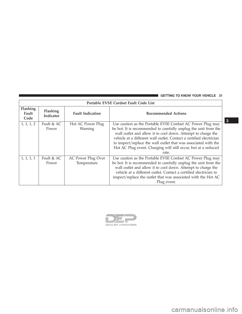
Portable EVSE Cordset Fault Code List
Flashing Fault
Code Flashing
Indicator Fault Indication Recommended Actions
1, 1, 1, 2 Fault & AC PowerHot AC Power Plug
Warning Use caution as the Portable EVSE Cordset AC Power Plug may
be hot. It is recommended to carefully unplug the unit from the wall outlet and allow it to cool down. Attempt to charge the
vehicle at a different wall outlet. Contact a certified electrician
to inspect/replace the wall outlet that was associated with the Hot AC Plug event. Charging will still occur, but at a reduced rate.
1, 1, 1, 1 Fault & AC PowerAC Power Plug Over
Temperature Use caution as the Portable EVSE Cordset AC Power Plug may
be hot. It is recommended to carefully unplug the unit from the wall outlet and allow it to cool down. Attempt to charge thevehicle at a different outlet. Contact a certified electrician to
inspect/replace the outlet that was associated with the Hot AC Plug event.
3
GETTING TO KNOW YOUR VEHICLE 31
Page 34 of 302
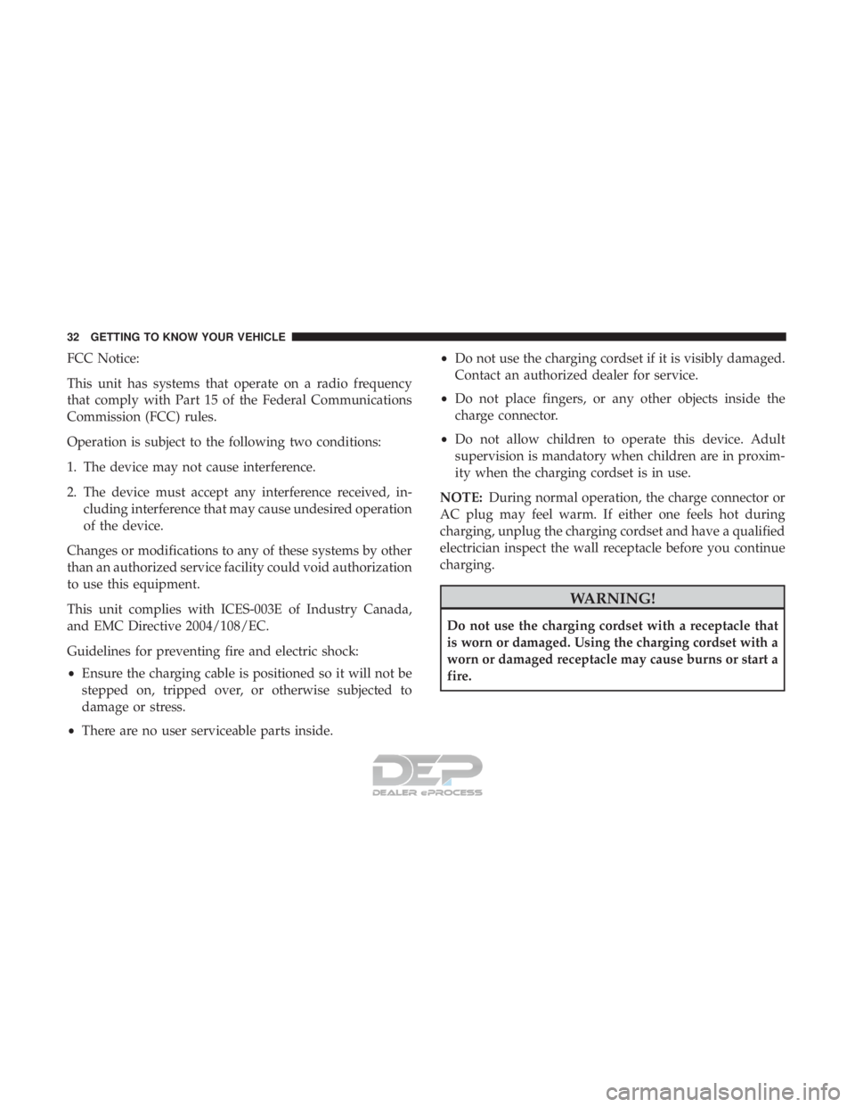
FCC Notice:
This unit has systems that operate on a radio frequency
that comply with Part 15 of the Federal Communications
Commission (FCC) rules.
Operation is subject to the following two conditions:
1. The device may not cause interference.
2. The device must accept any interference received, in-cluding interference that may cause undesired operation
of the device.
Changes or modifications to any of these systems by other
than an authorized service facility could void authorization
to use this equipment.
This unit complies with ICES-003E of Industry Canada,
and EMC Directive 2004/108/EC.
Guidelines for preventing fire and electric shock:
• Ensure the charging cable is positioned so it will not be
stepped on, tripped over, or otherwise subjected to
damage or stress.
• There are no user serviceable parts inside. •
Do not use the charging cordset if it is visibly damaged.
Contact an authorized dealer for service.
• Do not place fingers, or any other objects inside the
charge connector.
• Do not allow children to operate this device. Adult
supervision is mandatory when children are in proxim-
ity when the charging cordset is in use.
NOTE: During normal operation, the charge connector or
AC plug may feel warm. If either one feels hot during
charging, unplug the charging cordset and have a qualified
electrician inspect the wall receptacle before you continue
charging.
WARNING!
Do not use the charging cordset with a receptacle that
is worn or damaged. Using the charging cordset with a
worn or damaged receptacle may cause burns or start a
fire.
32 GETTING TO KNOW YOUR VEHICLE
Page 35 of 302
Vehicle Charge Indicators
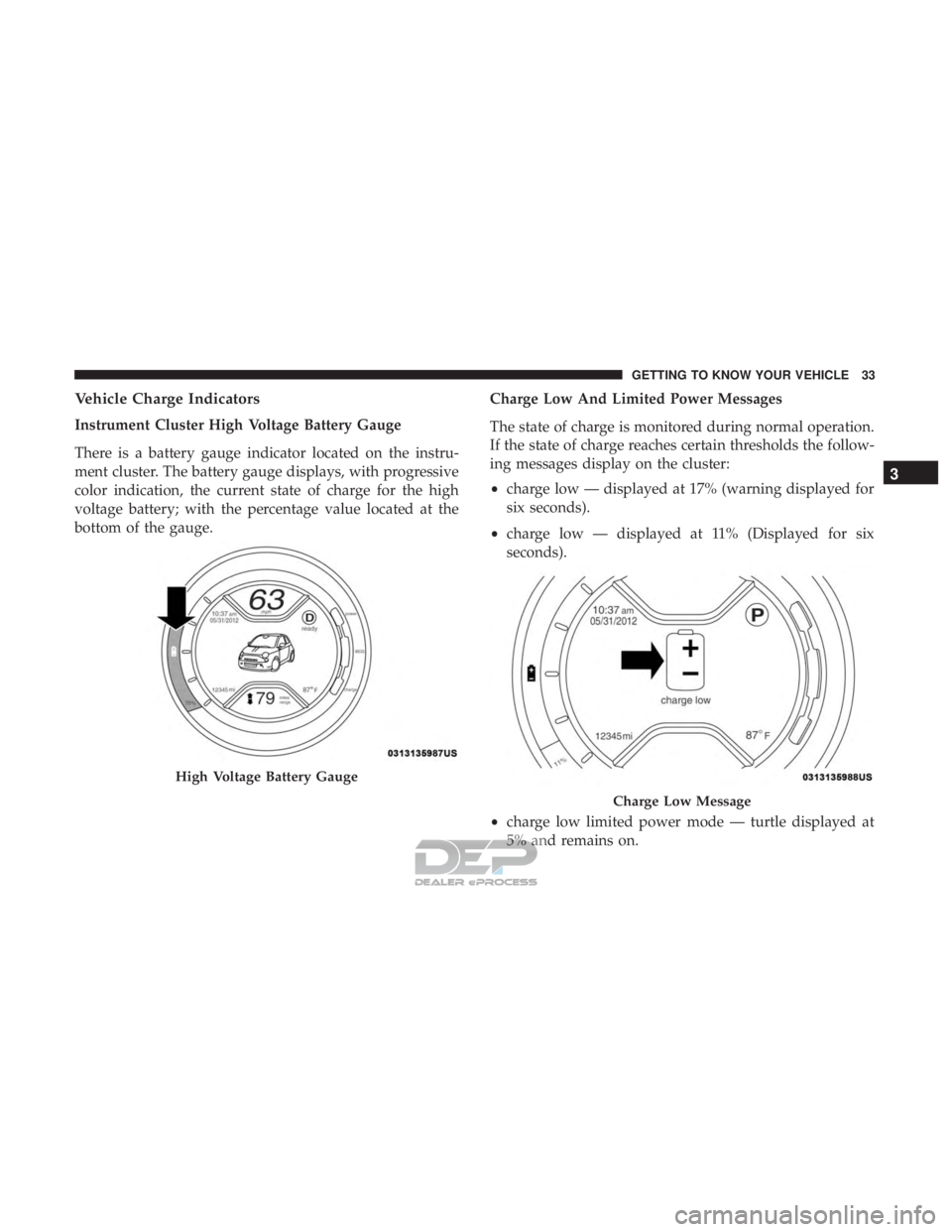
Instrument Cluster High Voltage Battery Gauge
There is a battery gauge indicator located on the instru-
ment cluster. The battery gauge displays, with progressive
color indication, the current state of charge for the high
voltage battery; with the percentage value located at the
bottom of the gauge.Charge Low And Limited Power Messages
The state of charge is monitored during normal operation.
If the state of charge reaches certain thresholds the follow-
ing messages display on the cluster:
•
charge low — displayed at 17% (warning displayed for
six seconds).
• charge low — displayed at 11% (Displayed for six
seconds).
• charge low limited power mode — turtle displayed at
5% and remains on.
High Voltage Battery Gauge
Charge Low Message
3
GETTING TO KNOW YOUR VEHICLE 33
Page 36 of 302
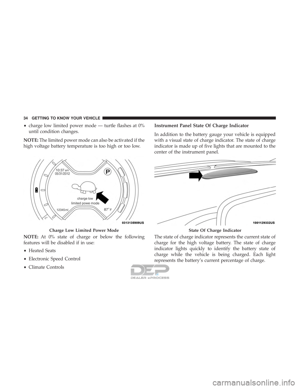
•charge low limited power mode — turtle flashes at 0%
until condition changes.
NOTE: The limited power mode can also be activated if the
high voltage battery temperature is too high or too low.
NOTE: At 0% state of charge or below the following
features will be disabled if in use:
• Heated Seats
• Electronic Speed Control
• Climate Controls Instrument Panel State Of Charge Indicator
In addition to the battery gauge your vehicle is equipped
with a visual state of charge indicator. The state of charge
indicator is made up of five lights that are mounted to the
center of the instrument panel.
The state of charge indicator represents the current state of
charge for the high voltage battery. The state of charge
indicator lights quickly to identify the battery state of
charge while the vehicle is being charged. Each light
represents the battery’s current percentage of charge.
Charge Low Limited Power ModeState Of Charge Indicator
34 GETTING TO KNOW YOUR VEHICLE
Page 37 of 302
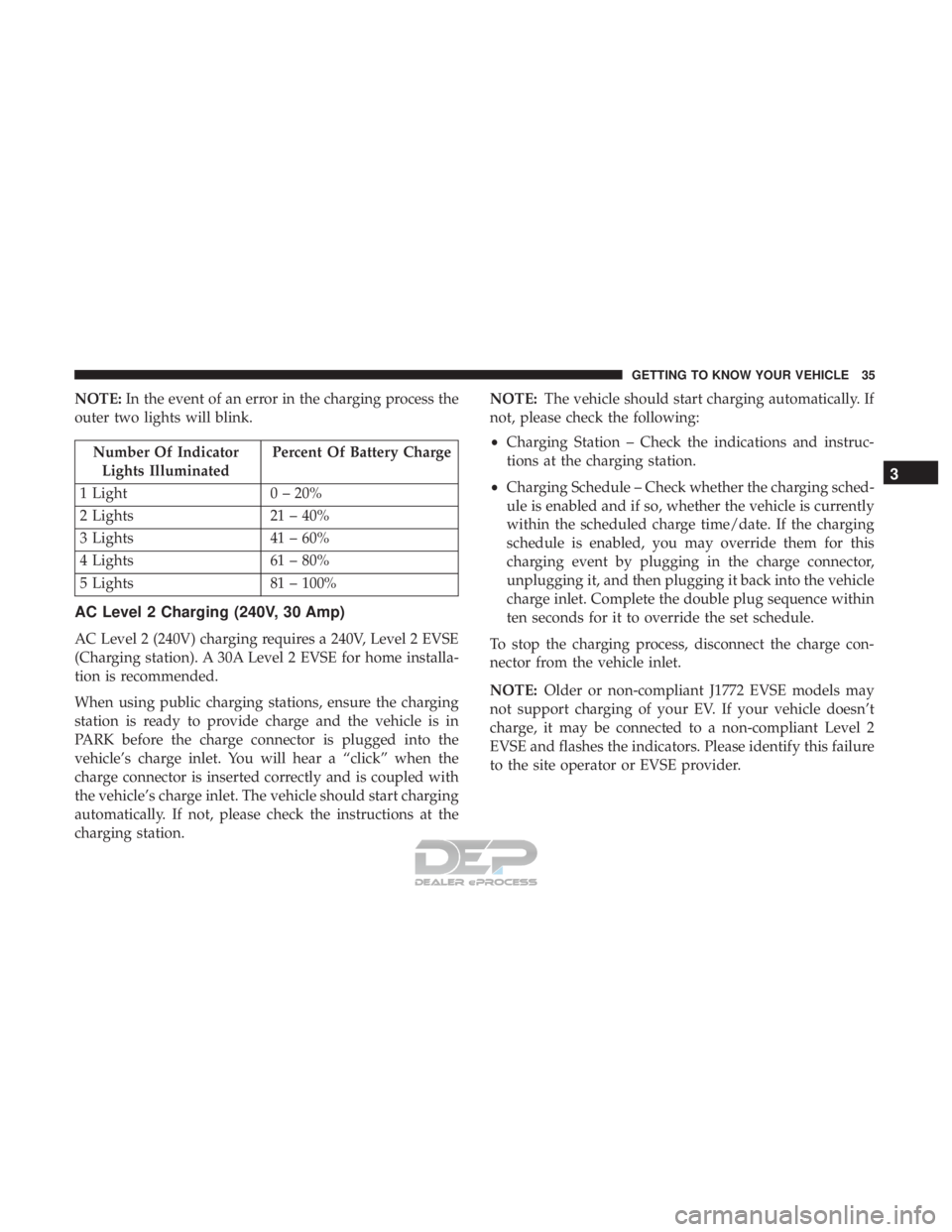
NOTE:In the event of an error in the charging process the
outer two lights will blink.
Number Of Indicator Lights Illuminated Percent Of Battery Charge
1 Light 0 – 20%
2 Lights 21 – 40%
3 Lights 41 – 60%
4 Lights 61 – 80%
5 Lights 81 – 100%
AC Level 2 Charging (240V, 30 Amp)
AC Level 2 (240V) charging requires a 240V, Level 2 EVSE
(Charging station). A 30A Level 2 EVSE for home installa-
tion is recommended.
When using public charging stations, ensure the charging
station is ready to provide charge and the vehicle is in
PARK before the charge connector is plugged into the
vehicle’s charge inlet. You will hear a “click” when the
charge connector is inserted correctly and is coupled with
the vehicle’s charge inlet. The vehicle should start charging
automatically. If not, please check the instructions at the
charging station. NOTE:
The vehicle should start charging automatically. If
not, please check the following:
• Charging Station – Check the indications and instruc-
tions at the charging station.
• Charging Schedule – Check whether the charging sched-
ule is enabled and if so, whether the vehicle is currently
within the scheduled charge time/date. If the charging
schedule is enabled, you may override them for this
charging event by plugging in the charge connector,
unplugging it, and then plugging it back into the vehicle
charge inlet. Complete the double plug sequence within
ten seconds for it to override the set schedule.
To stop the charging process, disconnect the charge con-
nector from the vehicle inlet.
NOTE: Older or non-compliant J1772 EVSE models may
not support charging of your EV. If your vehicle doesn’t
charge, it may be connected to a non-compliant Level 2
EVSE and flashes the indicators. Please identify this failure
to the site operator or EVSE provider.
3
GETTING TO KNOW YOUR VEHICLE 35
Page 38 of 302
Charge Times
The following factors determine the time it takes to charge
the high voltage battery:
•The high voltage battery’s current state of charge
• What level EVSE is being used (Level 1 – 120V or Level
2 – 240V)
• Ambient temperature
• Whether the vehicle is (keyed) on during charging
NOTE:
• The charging times are estimates based on a completely
discharged high voltage battery.
• Charging times will vary based on the age, condition,
state of charge and temperature of the high voltage
battery.
• Charging times may be longer if a thermal self-
protection reduces the charging current from the EVSE.
Type of Charge Estimated Charge Time
Level 1 (120V/15A) Approximately 23 hours
Level 2 (240V/30A) Approximately 4 hours
KEYS
Key With Remote Control
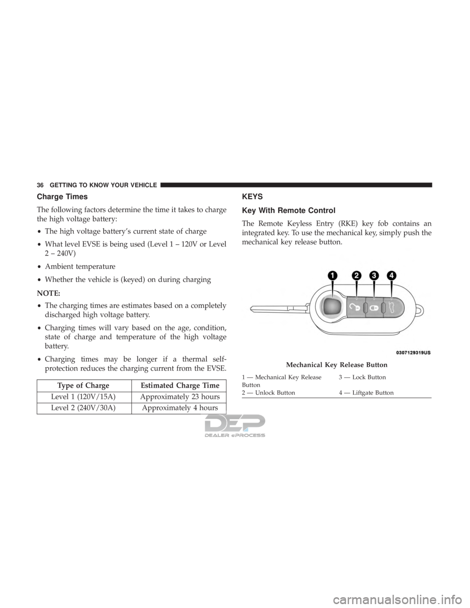
The Remote Keyless Entry (RKE) key fob contains an
integrated key. To use the mechanical key, simply push the
mechanical key release button.
Mechanical Key Release Button
1 — Mechanical Key Release
Button 3 — Lock Button
2 — Unlock Button 4 — Liftgate Button
36 GETTING TO KNOW YOUR VEHICLE
Page 39 of 302
NOTE:
•The authorized dealer that sold you your vehicle has the
key code numbers for your vehicle locks. These numbers
can be used to order duplicate keys from your autho-
rized dealer.
• When exiting the vehicle, remember to cycle the ignition
to the STOP (OFF/LOCK) position and remove the key
from the ignition switch to avoid draining the battery.
To Unlock The Doors And Liftgate
Push and release the unlock button on the key fob once to
unlock the driver ’s door or twice, within five seconds, to
unlock all doors, and the liftgate. The turn signal lights will
flash to acknowledge the unlock signal. The illuminated
entry system will also turn on.
To Lock The Doors And Liftgate
Push and release the lock button on the key fob to lock all
doors and the liftgate. The turn signal lights will flash and
the horn will chirp to acknowledge the signal.
Locking Doors With A Key
1. Insert the key with either side up.
2. Turn the key to the right to lock the door.
3. Turn the key to the left to unlock the door.
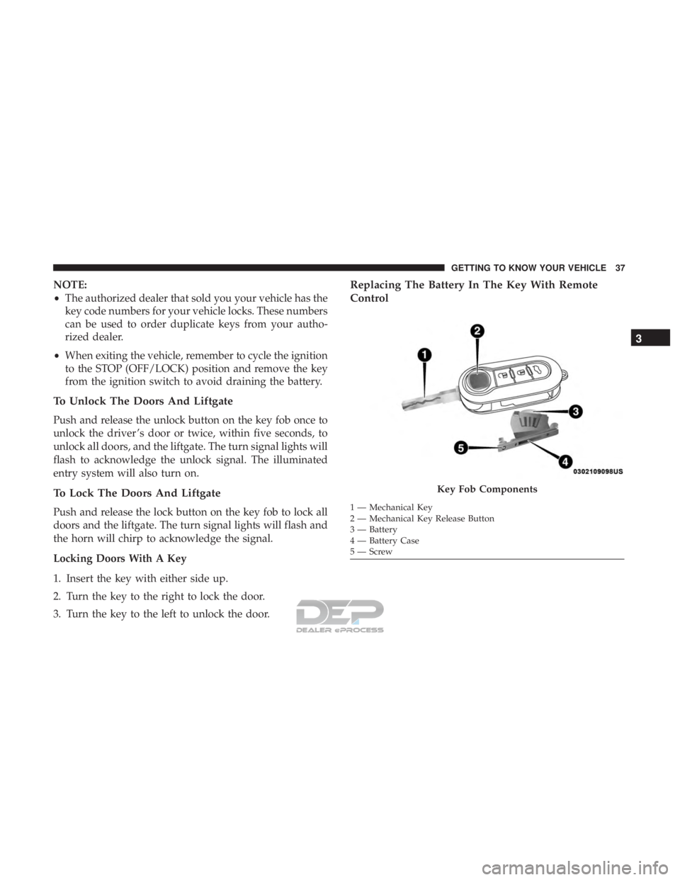
Replacing The Battery In The Key With Remote
Control
Key Fob Components
1 — Mechanical Key
2 — Mechanical Key Release Button
3 — Battery
4 — Battery Case
5—Screw
3
GETTING TO KNOW YOUR VEHICLE 37
Page 40 of 302
To replace the battery, proceed as follows:
1. Push mechanical release button to open the mechanicalkey.
2. Turn the screw to unlock using a small screwdriver.
3. Take out the battery case and replace the battery making sure that polarities are correct.
4. Refit the battery case inside the key and lock it turning the screw to lock.
NOTE: Used batteries should be properly disposed of as
specified by law, see an authorized dealer for assistance
needed.
Programming Additional Key Fobs
Refer to “Sentry Key” in “Getting To Know Your Vehicle”
for further information.
If you do not have a programmed key fob, contact an
authorized dealer for details.
Request For Additional Remote Controls
The system can recognize up to eight remote controls.
Should a new remote control be necessary, go to an
authorized dealer, taking an ID document and the car
ownership documents.
General Information
The following regulatory statement applies to all radio
frequency (RF) devices equipped in this vehicle:
This device complies with Part 15 of the FCC Rules and
with Industry Canada license-exempt RSS standard(s).
Operation is subject to the following two conditions:
1. This device may not cause harmful interference, and
2. This device must accept any interference received, in- cluding interference that may cause undesired opera-
tion.
NOTE: Changes or modifications not expressly approved
by the party responsible for compliance could void the
user ’s authority to operate the equipment.
IGNITION SWITCH
Mechanical Ignition Switch
The ignition switch can be turned to three different posi-
tions:
• STOP: the vehicle is off, and the key can be removed.
Some electrical devices (e.g. sound system, central door
locking system, etc.) can operate.
38 GETTING TO KNOW YOUR VEHICLE