door FIAT 500L 2014 2.G Owner's Manual
[x] Cancel search | Manufacturer: FIAT, Model Year: 2014, Model line: 500L, Model: FIAT 500L 2014 2.GPages: 116, PDF Size: 4.53 MB
Page 67 of 116
5.At the garage door opener motor (in the garage), locate the “LEARN” or “TRAINING”
button.This can usually be found where the hanging antenna wire is attached to the
garage
door opener motor.Firmly press and release the “LEARN” or “TRAINING” button.
NOTE:
You have 30 seconds in which to initiate the next step after the LEARN button has been
pressed.
6.Return to the vehicle and press the programmed HomeLink® button twice (holding
the button for two seconds each time).If the device is plugged in and activates, pro-
gramming is complete.
NOTE:
If the device does not activate, press the button a third time (for two seconds) to com-
plete the training.
7.To program the remaining two HomeLink® buttons, repeat each step for each
remaining button.DO NOT erase the channels.
Programming A Non-Rolling Code
NOTE:
For programming Garage Door Openers manufactured before 1995.
1.Turn the ignition switch to the ON/RUN position.
2.Place the hand-held transmitter 1 to 3 inches (3 to 8 cm) away from the HomeLink®
button you wish to program while keeping the HomeLink® indicator light in view.
3.Simultaneously press and hold both the HomeLink® button you want to program and
the hand-held transmitter button.
4.Continue to hold both buttons and observe the indicator light.The HomeLink® indi-
cator will flash slowly and then rapidly after HomeLink® has received the frequency
signal from the hand-held transmitter.Release both buttons after the indicator light
changes from slow to rapid.
5.Press and hold the programmed HomeLink® button and observe the indicator light.
If the indicator light stays on constantly, programming is complete and the garage door
(or device) should activate when the HomeLink® button is pressed.
6.To program the two remaining HomeLink® buttons, repeat each step for each re-
maining button.DO NOT erase the channels.
Using HomeLink®
To operate, press and release the programmed HomeLink® button.Activation will now
occur for the programmed device (i.e., garage door opener, gate operator, security sys-
tem, entry door lock, home/office lighting, etc.,).The hand-held transmitter of the device
may also be used at any time.
ELECTRONICS
65
Page 68 of 116
WARNING!
•Your motorized door or gate will open and close while you are programming the
universal transceiver.Do not program the transceiver if people or pets are in the
path of the door or gate.
•Do not run your vehicle in a closed garage or confined area while programming
the transceiver.Exhaust gas from your vehicle contains Carbon Monoxide (CO)
which is odorless and colorless.Carbon Monoxide is poisonous when inhaled and
can cause you and others to be severely injured or killed.
POWER INVERTER
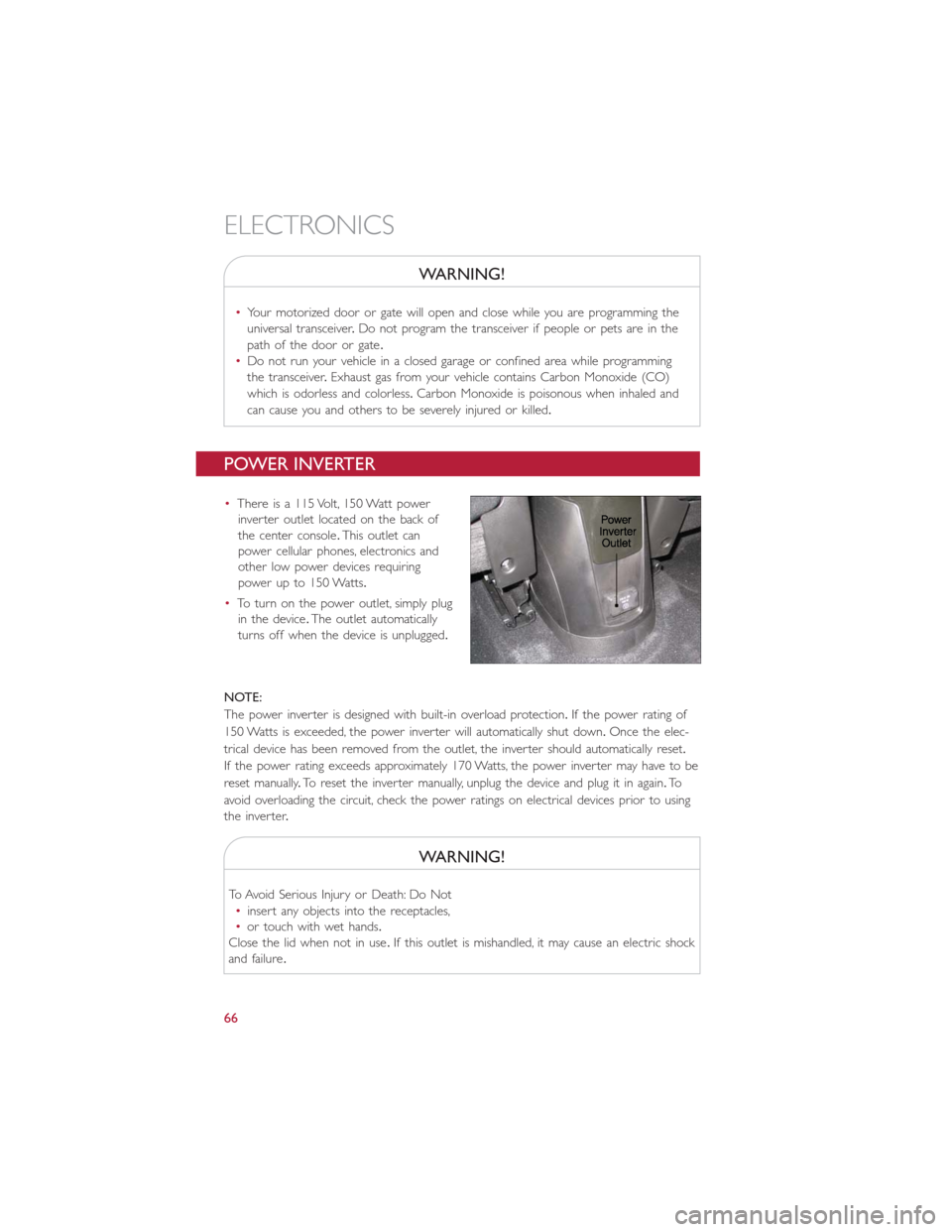
•There is a 115 Volt, 150 Watt power
inverter outlet located on the back of
the center console.This outlet can
power cellular phones, electronics and
other low power devices requiring
power up to 150 Watts.
•To turn on the power outlet, simply plug
in the device.The outlet automatically
turns off when the device is unplugged.
NOTE:
The power inverter is designed with built-in overload protection.If the power rating of
150 Watts is exceeded, the power inverter will automatically shut down.Once the elec-
trical device has been removed from the outlet, the inverter should automatically reset.
If the power rating exceeds approximately 170 Watts, the power inverter may have to be
reset manually.To reset the inverter manually, unplug the device and plug it in again.To
avoid overloading the circuit, check the power ratings on electrical devices prior to using
the inver ter.
WARNING!
To Avoid Serious Injury or Death: Do Not
•insert any objects into the receptacles,
•or touch with wet hands.
Close the lid when not in use.If this outlet is mishandled, it may cause an electric shock
and failure.
ELECTRONICS
66
Page 73 of 116
NOTE:
•The “ESC Off Indicator Light” and the “ESC Activation/Malfunction Indicator Light”
come on momentarily each time the ignition switch is turned to ON/RUN.
•Each time the ignition is turned to ON/RUN, the ESC system will be ON even if it
was turned off previously.
•ESC Activation/Malfunction Light can blink during a ESC or TC intervention.
- Tire Pressure Monitoring System (TPMS) Light
Each tire, including the spare (if provided), should be checked monthly when cold and
inflated to the inflation pressure recommended by the vehicle manufacturer on the ve-
hicle placard or tire inflation pressure label.(If your vehicle has tires of a different size
than the size indicated on the vehicle placard or tire inflation pressure label, you should
determine the proper tire inflation pressure for those tires.)
As an added safety feature, your vehicle has been equipped with a tire pressure monitoring
system (TPMS) that illuminates a low tire pressure telltale when one or more of your tires is
significantly under-inflated.Accordingly, when the low tire pressure telltale illuminates, you
should stop and check your tires as soon as possible, and inflate them to the proper pressure.
Driving on a significantly under-inflated tire causes the tire to overheat and can lead to tire
failure.Under-inflation also reduces fuel efficiency and tire tread life, and may affect the vehi-
cle’s handling and stopping ability.
IF THE LIGHT STARTS FLASHING INDICATING A LOW TIRE PRESSURE, ADJUST
THE AIR PRESSURE IN THE LOW TIRE TO THE AIR PRESSURE SHOWN ON THE
VEHICLE PLACARD OR TIRE INFLATION PRESSURE LABEL LOCATED ON THE
DRIVER'S DOOR.
NOTE:
AFTER INFLATION, THE VEHICLE MAY NEED TO BE DRIVEN FOR 20 MINUTES
BEFORE THE FLASHING LIGHT WILL TURN OFF.
Please note that the TPMS is not a substitute for proper tire maintenance, and it is the
driver’s responsibility to maintain correct tire pressure, even if under-inflation has not
reached the level to trigger illumination of the TPMS low tire pressure telltale.
Your vehicle has also been equipped with a TPMS malfunction indicator to indicate when
the system is not operating properly.The TPMS malfunction indicator is combined with
the low tire pressure telltale.
When the system detects a malfunction, the telltale will flash for approximately one min-
ute and then remain continuously illuminated.This sequence will continue upon subse-
quent vehicle start-ups as long as the malfunction exists.When the malfunction indicator
is illuminated, the system may not be able to detect or signal low tire pressure as in-
tended.TPMS malfunctions may occur for a variety of reasons, including the installation of
replacement or alternate tires or wheels on the vehicle that prevent the TPMS from
functioning properly.Always check the TPMS malfunction telltale after replacing one or
more tires or wheels on your vehicle to ensure that the replacement or alternate tires
and wheels allow the TPMS to continue to function properly.
WHAT TO DO IN EMERGENCIES
71
Page 86 of 116
If the tire does not inflate to at least 26 psi (1.8 Bar) pressure within 15 minutes:
The tire is too badly damaged.Do not attempt to drive the vehicle further.Call for assis-
tance.
NOTE:
If the tire becomes over-inflated, press the Deflation Button to reduce the tire pressure
to the recommended inflation pressure before continuing.
If the tire inflates to the recommended pressure or is at least 26 psi (1.8 Bar) pressure
within 15 minutes:
1.Press the Power Button (4) to turn off the TIREFIT kit.
2.Remove the Speed Limit sticker from the top of the Sealant Bottle (1) and place the
sticker on the instrument panel.
3.Immediately disconnect the Sealant Hose (6) from the valve stem, reinstall the cap
on the fitting at the end of the hose, and place the TIREFIT kit in the vehicle storage
location.Quickly proceed to (D) “Drive Vehicle.”
(D) Drive Vehicle:
Immediately after injecting sealant and inflating the tire, drive the vehicle 5 miles (8 km)
or 10 minutes to ensure distribution of the TIREFIT Sealant within the tire.Do not
exceed 55 mph (88 km/h).
(E) After Driving:
Pull over to a safe location.Refer to “Whenever You Stop to Use TIREFIT” before continuing.
1.Turn the Mode Select Knob (5) to the Air Mode position.
2.Uncoil the Air Pump Hose (7) (black in color) and screw the fitting at the end of
hose (7) onto the valve stem.
3.Uncoil the power plug and insert the plug into the vehicles 12 Volt power outlet.
4.Check the pressure in the tire by reading the Pressure Gauge (3).
If tire pressure is less than 19 psi (1.3 Bar), the tire is too badly damaged. Do not
attempt to drive the vehicle further. Call for assistance.
If the tire pressure is 19 psi (1.3 Bar) or higher:
1.Press the Power Button (4) to turn on TIREFIT and inflate the tire to the pressure
indicated on the tire and loading information label on the driver-side door opening.
2.Disconnect the TIREFIT kit from the valve stem, reinstall the cap on the valve stem
and unplug from 12 Volt outlet.
3.Place the TIREFIT kit in its proper storage area in the vehicle.
4.Have the tire inspected and repaired or replaced at the earliest opportunity at an
authorized dealer or tire service center.
5.Replace the Sealant Bottle (1) and Sealant Hose (6) assembly at your authorized
dealer as soon as possible.Refer to “(F) Sealant Bottle and Hose Replacement.”
WHAT TO DO IN EMERGENCIES
84
Page 95 of 116
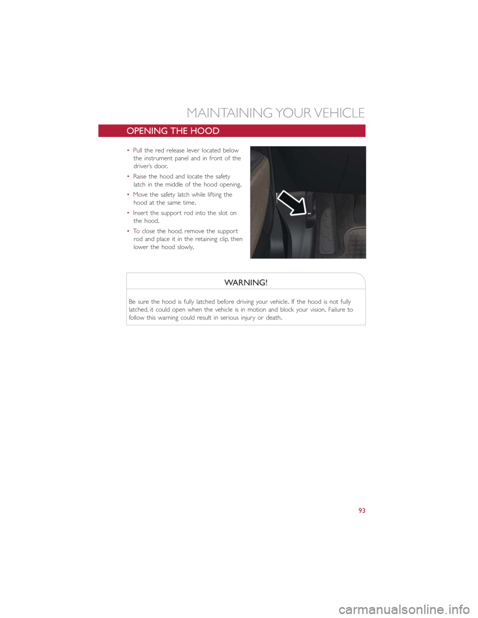
OPENING THE HOOD
•Pull the red release lever located below
the instrument panel and in front of the
driver’s door.
•Raise the hood and locate the safety
latch in the middle of the hood opening.
•Move the safety latch while lifting the
hood at the same time.
•Insert the support rod into the slot on
the hood.
•To close the hood, remove the support
rod and place it in the retaining clip, then
lower the hood slowly.
WARNING!
Be sure the hood is fully latched before driving your vehicle.If the hood is not fully
latched, it could open when the vehicle is in motion and block your vision.Failure to
follow this warning could result in serious injury or death.
MAINTAINING YOUR VEHICLE
93
Page 103 of 116
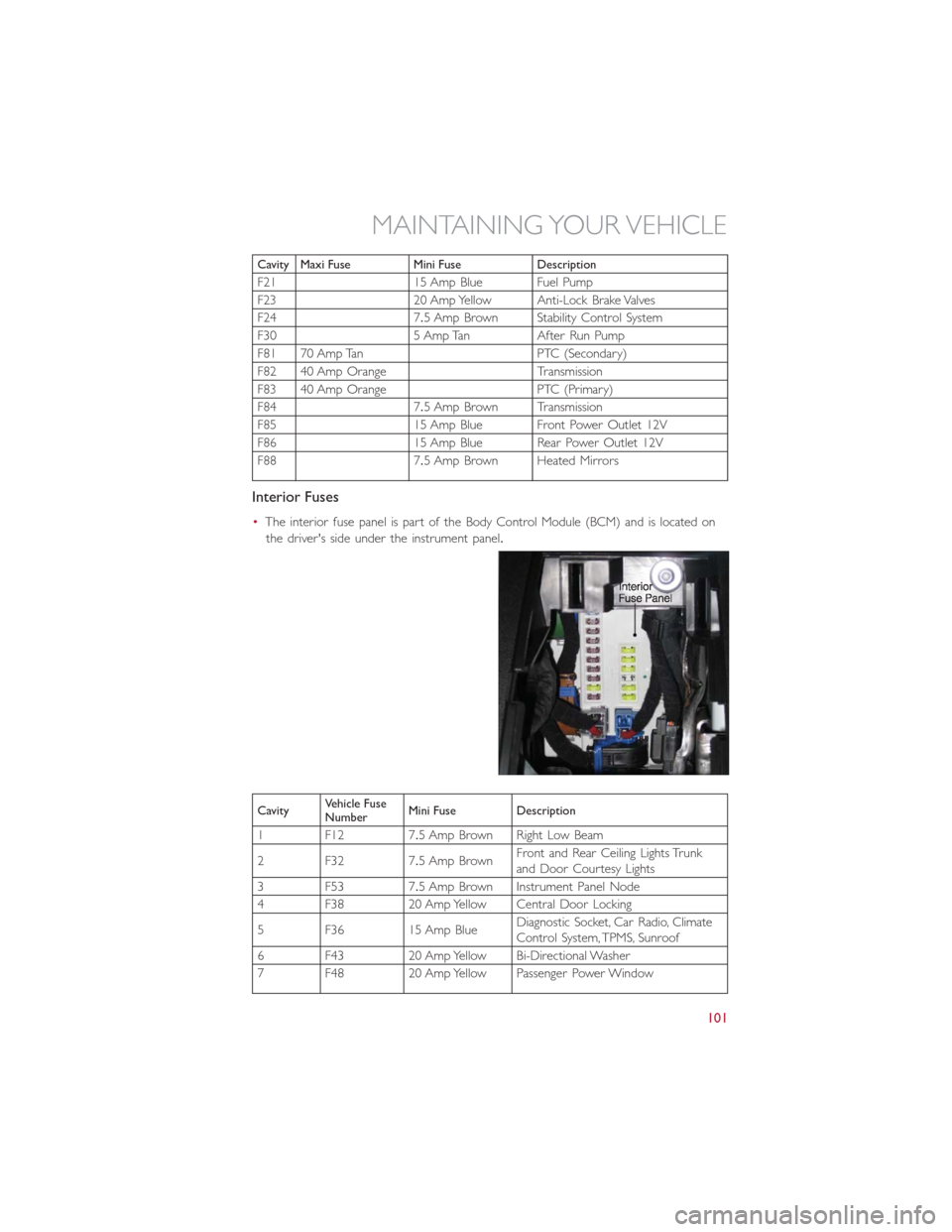
Cavity Maxi Fuse Mini Fuse Description
F21 15 Amp Blue Fuel Pump
F23 20 Amp Yellow Anti-Lock Brake Valves
F24 7.5 Amp Brown Stability Control System
F30 5 Amp Tan After Run Pump
F81 70 Amp Tan PTC (Secondary)
F82 40 Amp Orange Transmission
F83 40 Amp Orange PTC (Primary)
F84 7.5 Amp Brown Transmission
F85 15 Amp Blue Front Power Outlet 12V
F86 15 Amp Blue Rear Power Outlet 12V
F88 7.5 Amp Brown Heated Mirrors
Interior Fuses
•The interior fuse panel is part of the Body Control Module (BCM) and is located on
the driver's side under the instrument panel.
CavityVehicle Fuse
NumberMini Fuse Description
1 F12 7.5 Amp Brown Right Low Beam
2 F32 7.5 Amp BrownFront and Rear Ceiling Lights Trunk
and Door Courtesy Lights
3 F53 7.5 Amp Brown Instrument Panel Node
4 F38 20 Amp Yellow Central Door Locking
5 F36 15 Amp BlueDiagnostic Socket, Car Radio, Climate
Control System, TPMS, Sunroof
6 F43 20 Amp Yellow Bi-Directional Washer
7 F48 20 Amp Yellow Passenger Power Window
MAINTAINING YOUR VEHICLE
101
Page 105 of 116
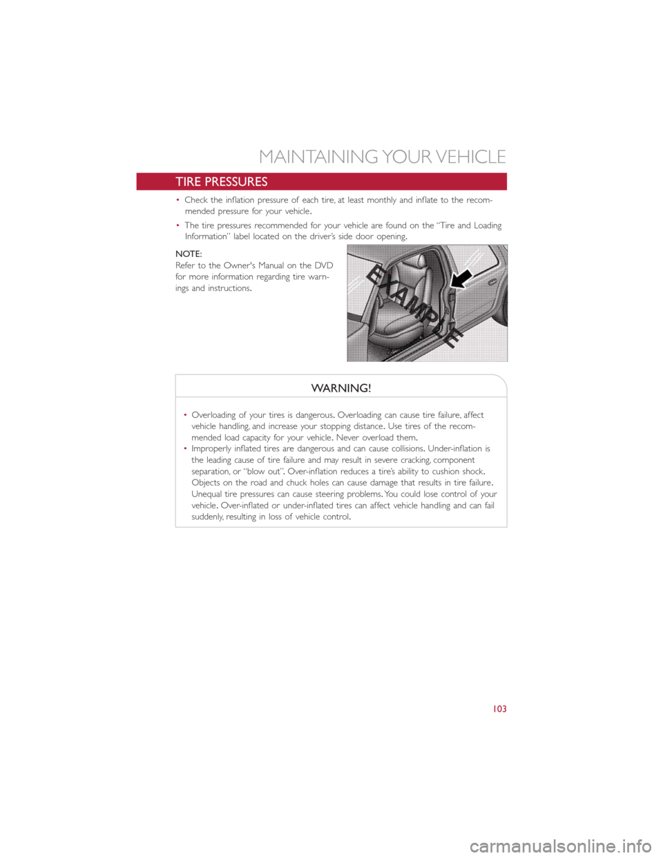
TIRE PRESSURES
•Check the inflation pressure of each tire, at least monthly and inflate to the recom-
mended pressure for your vehicle.
•The tire pressures recommended for your vehicle are found on the “Tire and Loading
Information” label located on the driver’s side door opening.
NOTE:
Refer to the Owner's Manual on the DVD
for more information regarding tire warn-
ings and instructions.
WARNING!
•Overloading of your tires is dangerous.Overloading can cause tire failure, affect
vehicle handling, and increase your stopping distance.Use tires of the recom-
mended load capacity for your vehicle.Never overload them.
•Improperly inflated tires are dangerous and can cause collisions.Under-inflation is
the leading cause of tire failure and may result in severe cracking, component
separation, or “blow out”.Over-inflation reduces a tire’s ability to cushion shock.
Objects on the road and chuck holes can cause damage that results in tire failure.
Unequal tire pressures can cause steering problems.You could lose control of your
vehicle.Over-inflated or under-inflated tires can affect vehicle handling and can fail
suddenly, resulting in loss of vehicle control.
MAINTAINING YOUR VEHICLE
103
Page 109 of 116
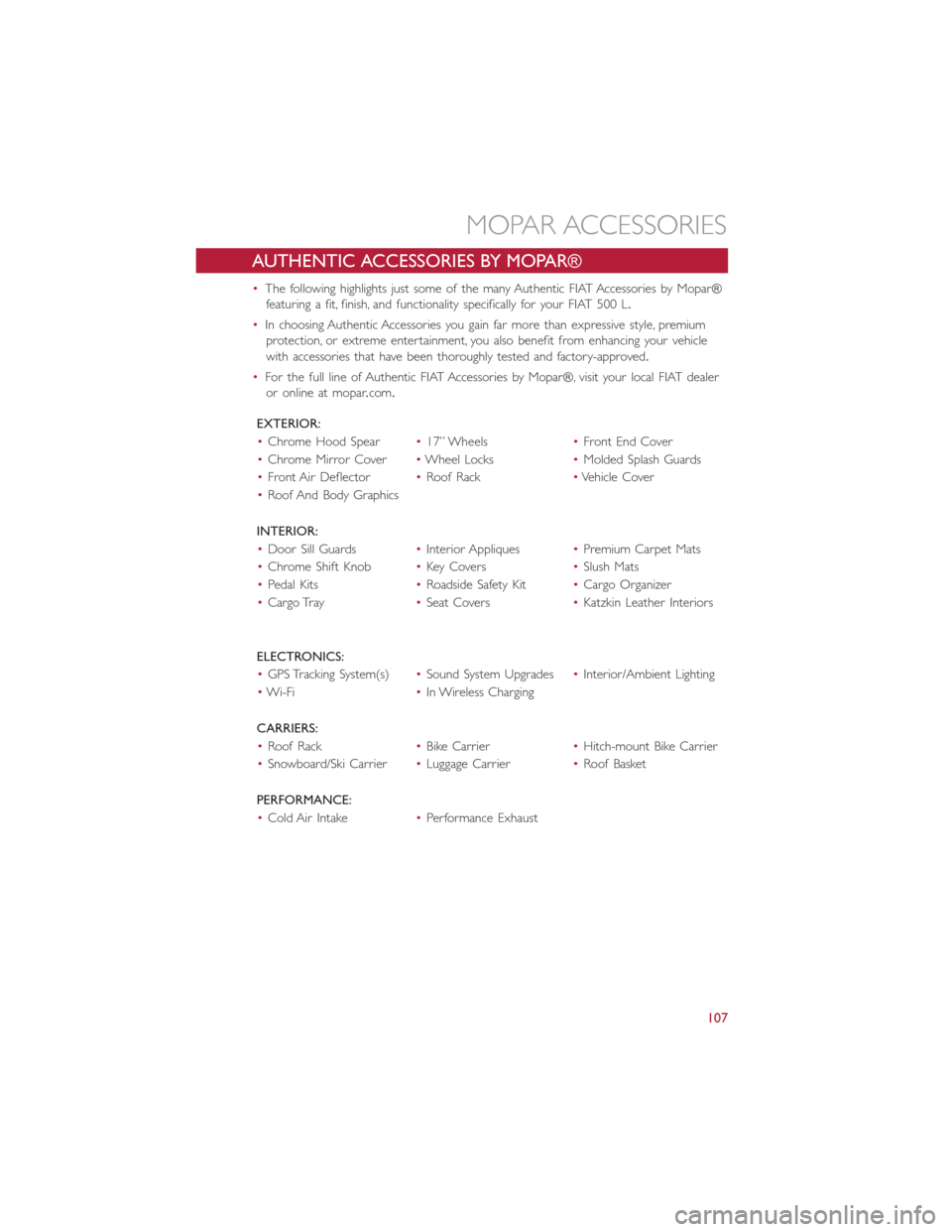
AUTHENTIC ACCESSORIES BY MOPAR®
•The following highlights just some of the many Authentic FIAT Accessories by Mopar®
featuring a fit, finish, and functionality specifically for your FIAT 500 L.
•In choosing Authentic Accessories you gain far more than expressive style, premium
protection, or extreme entertainment, you also benefit from enhancing your vehicle
with accessories that have been thoroughly tested and factory-approved.
•For the full line of Authentic FIAT Accessories by Mopar®, visit your local FIAT dealer
or online at mopar.com.
EXTERIOR:
•Chrome Hood Spear•17” Wheels•Front End Cover
•Chrome Mirror Cover•Wheel Locks•Molded Splash Guards
•Front Air Deflector•Roof Rack•Vehicle Cover
•Roof And Body Graphics
INTERIOR:
•Door Sill Guards•Interior Appliques•Premium Carpet Mats
•Chrome Shift Knob•Key Covers•Slush Mats
•Pedal Kits•Roadside Safety Kit•Cargo Organizer
•Cargo Tray•Seat Covers•Katzkin Leather Interiors
ELECTRONICS:
•GPS Tracking System(s)•Sound System Upgrades•Interior/Ambient Lighting
•Wi-Fi•In Wireless Charging
CARRIERS:
•Roof Rack•Bike Carrier•Hitch-mount Bike Carrier
•Snowboard/Ski Carrier•Luggage Carrier•Roof Basket
PERFORMANCE:
•Cold Air Intake•Performance Exhaust
MOPAR ACCESSORIES
107
Page 111 of 116
Adding Fuel.................30
Airbag....................11
Air Bag
Advance Front Air Bag.........11
Driver Knee Air Bag...........11
Front Air Bag..............11
Front Passenger Knee Air bag......11
Knee Impact Bolsters..........11
Side Air Bags...............11
Airbag Light...............11, 73
Alarm
Disarm The System............9
Vehicle Security Alarm..........8
Alarm (Security Alarm)............8
Anti-Lock Warning Light...........73
Audio Systems (Radio)...........33
Break-In Recommendations, New Vehicle..19
Bulb Replacement.............104
Caps, Filler..................30
Fuel...................92
Changing A Flat Tire.............75
Charging System Light............73
Child Restraint................12
Child Restraints
Child Seat Installation..........14
Installing Child Restraints Using The
Vehicle Seat Belt.............14
Lower Anchors And Tethers For
Children.................14
Using The Top Tether Anchorage....14
Child Seat..................14
Climate Control
Automatic................25
Manual..................24
Cluster Warning/Indicator Lights
Anti-Lock Brake (ABS) Light......73
Charging System Light.........73
Electronic Throttle Control (ETC)
Indicator Light..............70
Engine Temperature Warning Light...69
Malfunction Indicator Light (MIL)....72
Oil Pressure Warning Light.......73
Seat Belt Reminder Light........73
Tire Pressure Monitoring System
(TPMS) Light..............71Cruise Control (Speed Control)......22
Customer Assistance............105
Customer Programmable Features.....63
Defects, Reporting.............106
Disarming, Security System..........9
Door Locks.................8, 9
Driver Cockpit................4
Electronics
Your Vehicle's Sound System......32
Electronic Speed Control
(Cruise
Control).................22
Electronic Stability Control (ESC)......31
Electronic Throttle Control Warning Light...70
Electronic Vehicle Information Center
(EVIC)..................62
Emergency, In Case of
Brake Warning Light.........72, 73
Freeing Vehicle When Stuck......89
Jacking..................75
Towing.................90
Engine
Break-In Recommendations.......19
Compartment..............94
Overheating...............74
Temperature Warning Light.......69
Euro Twin Clutch Transmission.......27
Event Data Recorder............92
Exterior Lights...............104
Flash-To-Pass.................20
Folding Rear Seat..............17
Freeing A Stuck Vehicle...........91
Front Heated Seats.............18
Fuse....................100
Fuses....................100
Heated Mirrors.............24, 25
Heated Seats................18
HomeLink® (Garage Door Opener)....64
Hood Release................93
Identifying Your Radio............34
Information Center, Vehicle.........62
Instrument Cluster Warning Lights.....69
INDEX
109
Page 112 of 116
Interior and Instrument Lights........5
Inverter Outlet (115V)...........66
Inverter, Power...............66
Jack Operation................75
Key Fo b....................8
Disarm The Alarm.............9
Lane Change Assist.............19
LATCH (Lower Anchors and Tether
for CHildren)...........12, 13, 15
Liftgate....................8
Lights
Tire Pressure Monitoring (TPMS)...71
Turn Signal...............19
Locks
Key s...................8
Liftgate, Tailgate..............8
Maintenance Schedule............96
Malfunction Indicator Light
(Check Engine)..............72
Mirrors
Heated...............24, 25
Navigation..................52
New Vehicle Break-In Period........19
Oil Pressure Light..............73
Outlet
Power..................67
Overheating, Engine.............74
Phone (Pairing)...............39
Placard, Tire and Loading Information...103
Power
Door Locks...............9
Inver ter.................66
Outlet (Auxiliary Electrical Outlet)...67
Steering.................69
Programmable Electronic Features.....63
Rear Seat, Folding..............17
Reclining Front Seats............16
Recreational Towing.............68Remote Keyless Entry (RKE)Disarm The Alarm.............9
Replacement Bulbs.............104
Reporting Safety Defects..........106
Schedule, Maintenance............96
Seat Belt
Automatic Locking Retractor (ALR)...10
Child Restraints.............10
Energy Management Feature......10
Engage The Automatic Locking Mode..14
Lap/Shoulder Belts............10
Seat Belt Pretensioner.........10
Seat Belt Reminder...........10
Seats
Adjustment...............16
Heated.................18
Rear Folding...............17
Security Alarm
Disarm The System............9
Security Alarm..............8
Signals, Turn.................19
Speed Control
Accel/Decel...............22
Cancel..................23
Speed Control (Cruise Control)......22
Steering
Tilt Column...............18
Steering Wheel Audio Controls.......62
Stuck, Freeing................91
Text Messaging..............41, 57
Tilt Steering Column............18
TIREFIT...................81
Tires
Air Pressure..............103
Changing................75
Jacking..................75
Towing
Disabled Vehicle.............90
Recreational...............68
Towing Vehicle Behind a Motorhome....68
Turn Signals.................19
Uconnect® 5.0...............35
Uconnect® 6.5N..............45
Uconnect® Voice Command........41
INDEX
110