park FIAT 500L 2014 2.G Owner's Manual
[x] Cancel search | Manufacturer: FIAT, Model Year: 2014, Model line: 500L, Model: FIAT 500L 2014 2.GPages: 116, PDF Size: 4.53 MB
Page 31 of 116
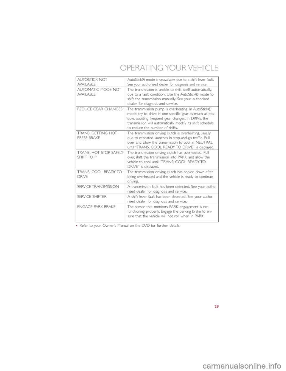
AUTOSTICK NOT
AVAILABLEAutoStick® mode is unavailable due to a shift lever fault.
See your authorized dealer for diagnosis and service.
AUTOMATIC MODE NOT
AVAILABLEThe transmission is unable to shift itself automatically,
due to a fault condition.Use the AutoStick® mode to
shift the transmission manually.See your authorized
dealer for diagnosis and service.
REDUCE GEAR CHANGES The transmission pump is overheating.In AutoStick®
mode, try to drive in one specific gear as much as pos-
sible, avoiding frequent gear changes.In DRIVE, the
transmission will automatically modify its shift schedule
to reduce the number of shifts.
TRANS.GETTING HOT
PRESS BRAKEThe transmission driving clutch is overheating, usually
due to repeated launches in stop-and-go traffic.Pull
over and allow the transmission to cool in NEUTRAL
until “TRANS.COOL READY TO DRIVE” is displayed.
TRANS.HOT STOP SAFELY
SHIFT TO PThe transmission driving clutch has overheated.Pull
over, shift the transmission into PARK, and allow the
vehicle to cool until “TRANS.COOL READY TO
DRIVE” is displayed.
TRANS.COOL READY TO
DRIVEThe transmission driving clutch has cooled down after
being overheated and the vehicle is ready to continue
driving.
SERVICE TRANSMISSION A transmission fault has been detected.See your autho-
rized dealer for diagnosis and service.
SERVICE SHIFTER A shift lever fault has been detected.See your autho-
rized dealer for diagnosis and service.
ENGAGE PARK BRAKE The sensor that monitors PARK engagement is not
functioning properly.Engage the parking brake to en-
sure that the vehicle will not roll when in PARK.
•Refer to your Owner's Manual on the DVD for further details.
OPERATING YOUR VEHICLE
29
Page 66 of 116
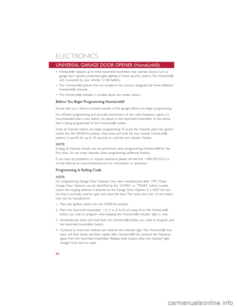
UNIVERSAL GARAGE DOOR OPENER (HomeLink®)
•HomeLink® replaces up to three hand-held transmitters that operate devices such as
garage door openers, motorized gates, lighting or home security systems.The HomeLink®
unit is powered by your vehicles 12 Volt battery.
•The HomeLink® buttons that are located in the sunvisor designate the three different
HomeLink® channels.
•The HomeLink® indicator is located above the center button.
Before You Begin Programming HomeLink®
Ensure that your vehicle is parked outside of the garage before you begin programming.
For efficient programming and accurate transmission of the radio-frequency signal, it is
recommended that a new battery be placed in the hand-held transmitter of the device
that is being programmed to the HomeLink® system.
Erase all channels before you begin programming.To erase the channels, place the ignition
switch into the ON/RUN position, then press and hold the two outside HomeLink®
buttons (I and III) for up to 20 seconds or until the red indicator flashes.
NOTE:
Erasing all channels should only be performed when programming HomeLink® for the
first time.Do not erase channels when programming additional buttons.
If you have any problems, or require assistance, please call toll-free 1-800-355-3515 or,
on the Internet at www.HomeLink.com for information or assistance.
Programming A Rolling Code
NOTE:
For programming Garage Door Openers that were manufactured after 1995.These
Garage Door Openers can be identified by the “LEARN” or “TRAIN” button located
where the hanging antenna is attached to the Garage Door Opener.It is NOT the but-
ton that is normally used to open and close the door.The name and color of the button
may vary by manufacturer.
1.Place the ignition switch into the ON/RUN position.
2.Place the hand-held transmitter 1 to 3 in (3 to 8 cm) away from the HomeLink®
button you wish to program while keeping the HomeLink® indicator light in view.
3.Simultaneously press and hold both the HomeLink® button you want to program and
the hand-held transmitter button.
4.Continue to hold both buttons and observe the indicator light.The HomeLink® indi-
cator will flash slowly and then rapidly after HomeLink® has received the frequency
signal from the hand-held transmitter.Release both buttons after the indicator light
changes from slow to rapid.
ELECTRONICS
64
Page 71 of 116
24-HOUR ROADSIDE ASSISTANCE
•If your FIAT 500 L requires jump start assistance, out of gas/fuel delivery, tire service,
lockout service or towing due to a defect covered under the Basic Limited Warranty,
dial toll-free 1-888-242-6342 or 1-800-363-4869 for Canadian Residents.See your
Warranty booklet for further details.
•Provide your name, vehicle identification number and license plate number.
•Provide your location, including telephone number, from which you are calling.
•Briefly describe the nature of the problem and answer a few simple questions.
•You will be given the name of the service provider and an estimated time of arrival.
If you feel you are in an “unsafe situation,” please let us know.With your consent,
we will contact local police or safety authorities.
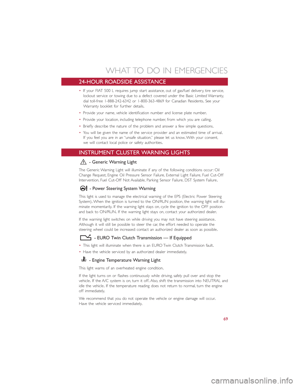
INSTRUMENT CLUSTER WARNING LIGHTS
- Generic Warning Light
The Generic Warning Light will illuminate if any of the following conditions occur: Oil
Change Request, Engine Oil Pressure Sensor Failure, External Light Failure, Fuel Cut-Off
Intervention, Fuel Cut-Off Not Available, Parking Sensor Failure, DST System Failure.
- Power Steering System Warning
This light is used to manage the electrical warning of the EPS (Electric Power Steering
System).When the ignition is turned to the ON/RUN position, the warning light will illu-
minate momentarily.If the warning light stays on, cycle the ignition to the OFF position
and back to ON/RUN.If the warning light stays on, contact your authorized dealer.
If the warning light switches on while driving you may not have steering assistance.
Although it will still be possible to steer the car, the effort needed to operate the
steering wheel could be increased: contact an authorized dealer as soon as possible.
- EURO Twin Clutch Transmission — If Equipped
•This light will illuminate when there is an EURO Twin Clutch Transmission fault.
•Have the vehicle serviced by an authorized dealer immediately.
- Engine Temperature Warning Light
This light warns of an overheated engine condition.
If the light turns on or flashes continuously while driving, safely pull over and stop the
vehicle.If the A/C system is on, turn it off.Also, shift the transmission into NEUTRAL and
idle the vehicle.If the temperature reading does not return to normal, turn the engine
off immediately.
We recommend that you do not operate the vehicle or engine damage will occur.
Have the vehicle serviced immediately.
WHAT TO DO IN EMERGENCIES
69
Page 72 of 116
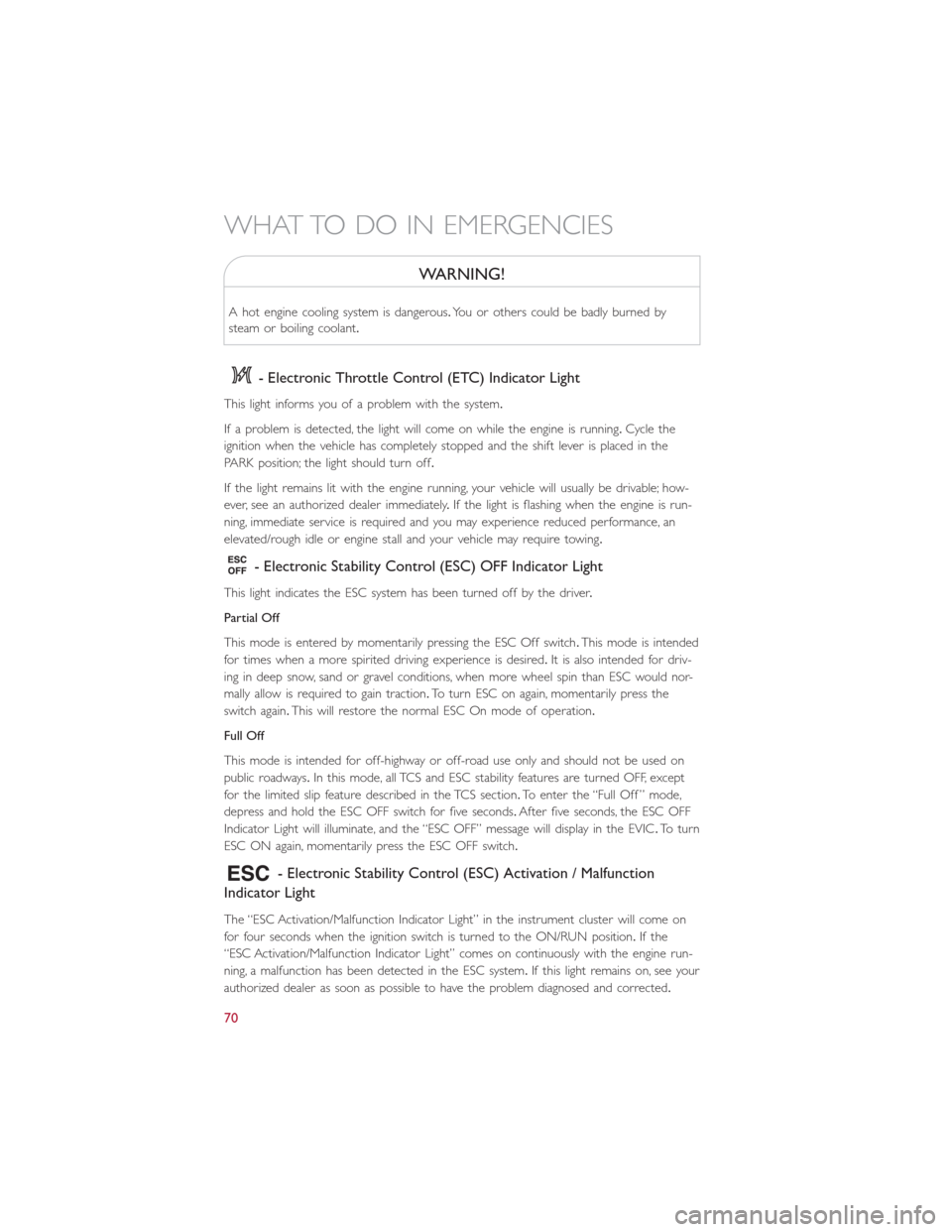
WARNING!
A hot engine cooling system is dangerous.You or others could be badly burned by
steam or boiling coolant.
- Electronic Throttle Control (ETC) Indicator Light
This light informs you of a problem with the system.
If a problem is detected, the light will come on while the engine is running.Cycle the
ignition when the vehicle has completely stopped and the shift lever is placed in the
PARK position; the light should turn off.
If the light remains lit with the engine running, your vehicle will usually be drivable; how-
ever, see an authorized dealer immediately.If the light is flashing when the engine is run-
ning, immediate service is required and you may experience reduced performance, an
elevated/rough idle or engine stall and your vehicle may require towing.
- Electronic Stability Control (ESC) OFF Indicator Light
This light indicates the ESC system has been turned off by the driver.
Partial Off
This mode is entered by momentarily pressing the ESC Off switch.This mode is intended
for times when a more spirited driving experience is desired.It is also intended for driv-
ing in deep snow, sand or gravel conditions, when more wheel spin than ESC would nor-
mally allow is required to gain traction.To turn ESC on again, momentarily press the
switch again.This will restore the normal ESC On mode of operation.
Full Off
This mode is intended for off-highway or off-road use only and should not be used on
public roadways.In this mode, all TCS and ESC stability features are turned OFF, except
for the limited slip feature described in the TCS section.To enter the “Full Off ” mode,
depress and hold the ESC OFF switch for five seconds.After five seconds, the ESC OFF
Indicator Light will illuminate, and the “ESC OFF” message will display in the EVIC.To turn
ESC ON again, momentarily press the ESC OFF switch.
- Electronic Stability Control (ESC) Activation / Malfunction
Indicator Light
The “ESC Activation/Malfunction Indicator Light” in the instrument cluster will come on
for four seconds when the ignition switch is turned to the ON/RUN position.If the
“ESC Activation/Malfunction Indicator Light” comes on continuously with the engine run-
ning, a malfunction has been detected in the ESC system.If this light remains on, see your
authorized dealer as soon as possible to have the problem diagnosed and corrected.
WHAT TO DO IN EMERGENCIES
70
Page 74 of 116
NOTE:
Tire pressures change by approximately 1 psi (7 kPa) per 12° F (7° C) of air tempera-
ture change.Keep this in mind when checking tire pressure inside a garage, especially in
the Winter.Example: If garage temperature is 68°F (20°C) and the outside temperature
is 32°F (0°C), then the cold tire inflation pressure should be increased by 3 psi (21 kPa),
which equals 1 psi (7 kPa) for every 12°F (7°C) for this outside temperature condition.
CAUTION!
The TPMS has been optimized for the original equipment tires and wheels.TPMS pres-
sures and warning have been established for the tire size equipped on your vehicle.
Undesirable system operation or sensor damage may result when using replacement
equipment that is not of the same size, type, and/or style.Aftermarket wheels can cause
sensor damage.Do not use tire sealant from a can, or balance beads if your vehicle is
equipped with a TPMS, as damage to the sensors may result.
BRAKE- Brake Warning Light
The Brake Warning light illuminates when there is either a system malfunction or the
parking brake is applied.If the light is on and the parking brake is not applied, it indicates
a possible brake hydraulic malfunction, brake booster problem or an Anti-Lock Brake Sys-
tem problem.
Please have your vehicle serviced immediately.
WARNING!
Driving a vehicle with the red brake light on is dangerous.Part of the brake system
may have failed.It will take longer to stop the vehicle.You could have a collision.Have
the vehicle checked immediately.
- Malfunction Indicator Light (MIL)
Certain conditions, such as a loose or missing gas cap, poor fuel quality, etc., may illumi-
nate the MIL after engine start.The vehicle should be serviced if the light stays on
through several typical driving cycles.In most situations, the vehicle will drive normally and
not require towing.
If the MIL flashes when the engine is running, serious conditions may exist that could lead
to immediate loss of power or severe catalytic converter damage.We recommend you
do not operate the vehicle.Have the vehicle serviced immediately.
WHAT TO DO IN EMERGENCIES
72
Page 79 of 116
Preparations For Jacking
1.Park the vehicle on a firm level surface, avoiding ice or slippery areas.
2.Turn on the Hazard Warning flashers.
3.Set the parking brake.
4.Place the shift lever in PARK (Euro Twin Clutch Transmission) or REVERSE (manual
transmission).
5.Turn Off the ignition.
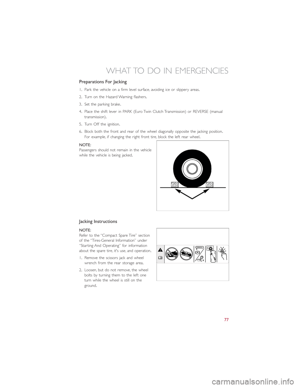
6.Block both the front and rear of the wheel diagonally opposite the jacking position.
For example, if changing the right front tire, block the left rear wheel.
NOTE:
Passengers should not remain in the vehicle
while the vehicle is being jacked.
Jacking Instructions
NOTE:
Refer to the “Compact Spare Tire” section
of the “Tires-General Information” under
“Starting And Operating” for information
about the spare tire, it's use, and operation.
1.Remove the scissors jack and wheel
wrench from the rear storage area.
2.Loosen, but do not remove, the wheel
bolts by turning them to the left one
turn while the wheel is still on the
ground.
WHAT TO DO IN EMERGENCIES
77
Page 82 of 116
WARNING!
•Do not attempt to change a tire on the side of the vehicle close to moving traffic.
Pull far enough off the road to avoid the danger of being hit when operating the
jack or changing the wheel.
•Being under a jacked-up vehicle is dangerous.The vehicle could slip off the jack
and fall on you.You could be crushed.Never put any part of your body under a
vehicle that is on a jack.
•Never start or run the engine while the vehicle is on a jack.if you need to get
under a raised vehicle, take it to a authorized dealer where it can be raised on a
lift.
•The jack is designed to use as a tool for changing tires only.The jack should not be
used to lift the vehicle for service purposes.The vehicle should be jacked on a
firm, level surface only.Avoid ice or slippery areas.
•After using the jack and tools, always reinstall them in the original carrier and loca-
tion.While driving you may experience abrupt stopping, rapid acceleration, or
sharp turns.A loose jack, tools, bracket or other objects in the vehicle may move
around with force, resulting in serious injury.
•Carefully follow these tire changing warnings to help prevent personal injury or
damage to your vehicle:
•Always park on a firm, level surface as far from the edge of the roadway as pos-
sible before raising the vehicle.
•Turn on the Hazard Warning flasher.
•Block the wheel diagonally opposite the wheel to be raised.
•Set the parking brake firmly and set the Euro Twin Clutch Transmission in PARK; a
manual transmission in REVERSE.
•Do not let anyone sit in the vehicle when it is on a jack.
•Do not get under the vehicle when it is on a jack.
•Only use the jack in the positions indicated and for lifting this vehicle during a tire
change.
•If working on or near a roadway, be extremely careful of motor traffic.
•To assure that spare tires, flat or inflated, are securely stowed, spares must be
stowed with the valve stem facing the ground.
•Raising the vehicle higher than necessary can make the vehicle unstable and cause
a collision.It could slip off the jack and hurt someone near it.Raise the vehicle
only enough to remove the tire.
•A loose tire or jack thrown forward in a collision or hard stop could injure some-
one in the vehicle.Always stow the jack parts and the extra tire and wheel in the
places provided.
WHAT TO DO IN EMERGENCIES
80
Page 84 of 116
TIREFIT Usage Precautions
•Replace the TIREFIT Sealant Bottle (1) and Sealant Hose (6) prior to the expiration
date (printed on the bottle label) to assure optimum operation of the system.Refer to
“Sealing a Tire with TIREFIT” section (F) “Sealant Bottle and Hose Replacement.”
•The Sealant Bottle (1) and Sealant Hose (6) are a one tire application use.After each
use, always replace these components immediately at an authorized dealer.
•When the TIREFIT sealant is in a liquid form, clean water, and a damp cloth will re-
move the material from the vehicle or tire and wheel components.Once the sealant
dries, it can easily be peeled off and properly discarded.
•For optimum performance, make sure the valve stem on the wheel is free of debris
before connecting the TIREFIT kit.
•
You can use the TIREFIT air pump to inflate bicycle tires.The kit also comes with two
needles, located in the Accessory Storage Compartment (on the bottom of the air pump)
for inflating sport balls, rafts, or similar inflatable items.However, use only the Air Pump
Hose (7) and make sure the Mode Select Knob (5) is in the Air Mode when inflating such
items to avoid injecting sealant into them.The TIREFIT Sealant is only intended to seal
punctures less than 1/4” (6 mm) diameter in the tread of your vehicle.
•Do not lift or carry the TIREFIT kit by the hoses.
Sealing A Tire With TIREFIT
(A) Whenever You Stop To Use TIREFIT:
1.Pull over to a safe location and turn on the vehicle’s Hazard Warning flashers.
2.Verify that the valve stem (on the wheel with the deflated tire) is in a position that is
near to the ground.This will allow the TIREFIT Hoses (6) and (7) to reach the valve
stem and keep the TIREFIT kit flat on the ground.This will provide the best position-
ing of the kit when injecting the sealant into the deflated tire and running the air
pump.Move the vehicle as necessary to place the valve stem in this position before
proceeding.
3.Place the transmission in PARK (auto transmission) or in Gear (manual transmission)
and cycle the ignition to the OFF position.
4.Set the parking brake.
(B) Setting Up To Use TIREFIT:
1.Turn the Mode Select Knob (5) to the Sealant Mode position.
2.Uncoil the Sealant Hose (6) and then remove the cap from the fitting at the end of
the hose.
3.Place the TIREFIT kit flat on the ground next to the deflated tire.
4.Remove the cap from the valve stem and then screw the fitting at the end of the
Sealant Hose (6) onto the valve stem.
5.Uncoil the Power Plug (8) and insert the plug into the vehicle’s 12 Volt power outlet.
6.Do not remove foreign objects (e.g., screws or nails) from the tire.
WHAT TO DO IN EMERGENCIES
82
Page 85 of 116
(C) Injecting TIREFIT Sealant Into The Deflated Tire:
Always start the engine before turning ON the TIREFIT kit.
NOTE:
Manual transmission vehicles must have the parking brake engaged and the shift lever in
NEUTRAL.
After pressing the Power Button (4), the sealant (white fluid) will flow from the Sealant
Bottle (1) through the Sealant Hose (6) and into the tire.
NOTE:
Sealant may leak out through the puncture in the tire.
If the sealant (white fluid) does not flow within0–10seconds through the Sealant Hose
(6):
1.Press the Power Button (4) to turn Off the TIREFIT kit.Disconnect the Sealant Hose
(6) from the valve stem.Make sure the valve stem is free of debris.Reconnect the
Sealant Hose (6) to the valve stem.Check that the Mode Select Knob (5) is in the
Sealant Mode position and not Air Mode.Press the Power Button (4) to turn On the
TIREFIT kit.
2.Connect the Power Plug (8) to a different 12 Volt power outlet in your vehicle or
another vehicle, if available.Make sure the engine is running before turning ON the
TIREFIT kit.
3.The Sealant Bottle (1) may be empty due to previous use.Call for assistance.
NOTE:
If the Mode Select Knob (5) is on Air Mode and the pump is operating, air will dispense
from the Air Pump Hose (7) only, not the Sealant Hose (6).
If the sealant (white fluid) does flow through the Sealant Hose (6):
1.Continue to operate the pump until sealant is no longer flowing through the hose
(typically takes 30 - 70 seconds).As the sealant flows through the Sealant Hose (6),
the Pressure Gauge (3) can read as high as 70 psi (4.8 Bar).The Pressure Gauge (3)
will decrease quickly from approximately 70 psi (4.8 Bar) to the actual tire pressure
when the Sealant Bottle (1) is empty.
2.The pump will start to inject air into the tire immediately after the Sealant Bottle (1)
is empty.Continue to operate the pump and inflate the tire to the pressure indicated
on the tire pressure label on the driver-side latch pillar (recommended pressure).
Check the tire pressure by looking at the Pressure Gauge (3).
WHAT TO DO IN EMERGENCIES
83
Page 89 of 116
Preparations For Jump-Start
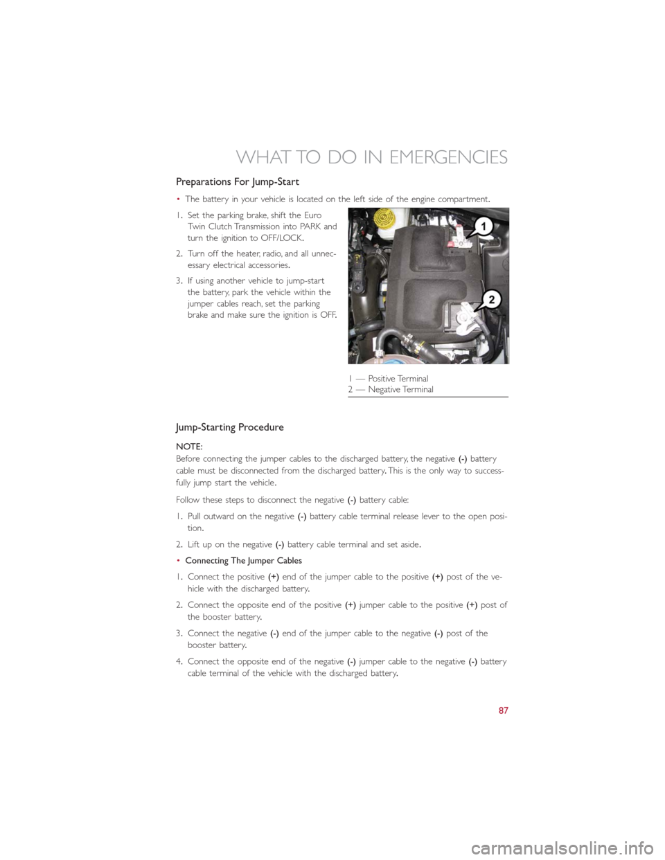
•The battery in your vehicle is located on the left side of the engine compartment.
1.Set the parking brake, shift the Euro
Twin Clutch Transmission into PARK and
turn the ignition to OFF/LOCK.
2.Turn off the heater, radio, and all unnec-
essary electrical accessories.
3.If using another vehicle to jump-start
the battery, park the vehicle within the
jumper cables reach, set the parking
brake and make sure the ignition is OFF.
Jump-Starting Procedure
NOTE:
Before connecting the jumper cables to the discharged battery, the negative(-)battery
cable must be disconnected from the discharged battery.This is the only way to success-
fully jump start the vehicle.
Follow these steps to disconnect the negative(-)battery cable:
1.Pull outward on the negative(-)battery cable terminal release lever to the open posi-
tion.
2.Lift up on the negative(-)battery cable terminal and set aside.
•Connecting The Jumper Cables
1.Connect the positive(+)end of the jumper cable to the positive(+)post of the ve-
hicle with the discharged battery.
2.Connect the opposite end of the positive(+)jumper cable to the positive(+)post of
the booster battery.
3.Connect the negative(-)end of the jumper cable to the negative(-)post of the
booster battery.
4.Connect the opposite end of the negative(-)jumper cable to the negative(-)battery
cable terminal of the vehicle with the discharged battery.
1 — Positive Terminal
2 — Negative Terminal
WHAT TO DO IN EMERGENCIES
87