lock FIAT 500L 2014 2.G Owner's Manual
[x] Cancel search | Manufacturer: FIAT, Model Year: 2014, Model line: 500L, Model: FIAT 500L 2014 2.GPages: 116, PDF Size: 4.53 MB
Page 78 of 116
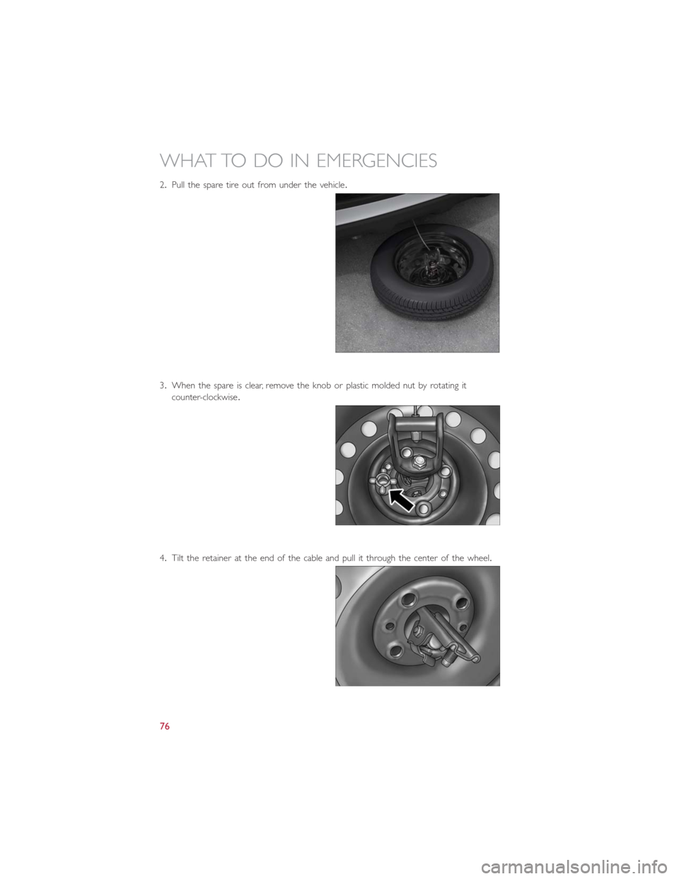
2.Pull the spare tire out from under the vehicle.
3.When the spare is clear, remove the knob or plastic molded nut by rotating it
counter-clockwise.
4.Tilt the retainer at the end of the cable and pull it through the center of the wheel.
WHAT TO DO IN EMERGENCIES
76
Page 79 of 116
Preparations For Jacking
1.Park the vehicle on a firm level surface, avoiding ice or slippery areas.
2.Turn on the Hazard Warning flashers.
3.Set the parking brake.
4.Place the shift lever in PARK (Euro Twin Clutch Transmission) or REVERSE (manual
transmission).
5.Turn Off the ignition.
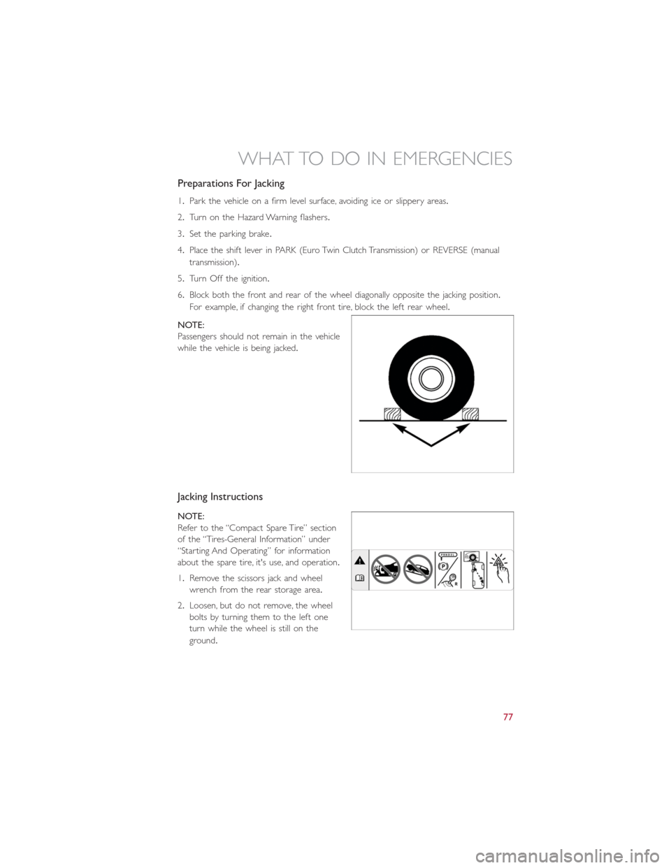
6.Block both the front and rear of the wheel diagonally opposite the jacking position.
For example, if changing the right front tire, block the left rear wheel.
NOTE:
Passengers should not remain in the vehicle
while the vehicle is being jacked.
Jacking Instructions
NOTE:
Refer to the “Compact Spare Tire” section
of the “Tires-General Information” under
“Starting And Operating” for information
about the spare tire, it's use, and operation.
1.Remove the scissors jack and wheel
wrench from the rear storage area.
2.Loosen, but do not remove, the wheel
bolts by turning them to the left one
turn while the wheel is still on the
ground.
WHAT TO DO IN EMERGENCIES
77
Page 81 of 116
8.Finish tightening the bolts.Push down on the wrench while tightening the wheel bolts.
Alternate bolts until each bolt has been tightened twice.The correct wheel bolt
torque is 63 ft lbs (86 N·m) for steel wheels and 89 ft lbs (120 N·m) for aluminum
wheels.If you doubt that you have tightened the bolts correctly, have them checked
with a torque wrench by your authorized dealer or service station.
9.Disassemble the jack and tools and place them in the in the rear cargo area.
10.Place the deflated (flat) tire in the cargo area.Have the tire repaired or replaced as
soon as possible.
11.Check the spare tire pressure as soon as possible.Correct the tire pressure as re-
quired.
Spare Tire Stowage
•Reverse instructions of the spare removal section.
•Rotate the jack wrench tool on the winch drive nut clockwise until effort becomes
heavy and an audible click is heard indicating the spare is properly stowed.
CAUTION!
•The winch mechanism is designed for use with the jack extension tube only.Use
of an air wrench or other power tools is not recommended and they can damage
the winch.
•Do not attempt to raise the vehicle by jacking on locations other than those indi-
cated in the Jacking Instructions for this vehicle.
•Be sure to mount the spare tire with the valve stem facing outward.The vehicle
could be damaged if the spare tire is mounted incorrectly.
WHAT TO DO IN EMERGENCIES
79
Page 82 of 116
WARNING!
•Do not attempt to change a tire on the side of the vehicle close to moving traffic.
Pull far enough off the road to avoid the danger of being hit when operating the
jack or changing the wheel.
•Being under a jacked-up vehicle is dangerous.The vehicle could slip off the jack
and fall on you.You could be crushed.Never put any part of your body under a
vehicle that is on a jack.
•Never start or run the engine while the vehicle is on a jack.if you need to get
under a raised vehicle, take it to a authorized dealer where it can be raised on a
lift.
•The jack is designed to use as a tool for changing tires only.The jack should not be
used to lift the vehicle for service purposes.The vehicle should be jacked on a
firm, level surface only.Avoid ice or slippery areas.
•After using the jack and tools, always reinstall them in the original carrier and loca-
tion.While driving you may experience abrupt stopping, rapid acceleration, or
sharp turns.A loose jack, tools, bracket or other objects in the vehicle may move
around with force, resulting in serious injury.
•Carefully follow these tire changing warnings to help prevent personal injury or
damage to your vehicle:
•Always park on a firm, level surface as far from the edge of the roadway as pos-
sible before raising the vehicle.
•Turn on the Hazard Warning flasher.
•Block the wheel diagonally opposite the wheel to be raised.
•Set the parking brake firmly and set the Euro Twin Clutch Transmission in PARK; a
manual transmission in REVERSE.
•Do not let anyone sit in the vehicle when it is on a jack.
•Do not get under the vehicle when it is on a jack.
•Only use the jack in the positions indicated and for lifting this vehicle during a tire
change.
•If working on or near a roadway, be extremely careful of motor traffic.
•To assure that spare tires, flat or inflated, are securely stowed, spares must be
stowed with the valve stem facing the ground.
•Raising the vehicle higher than necessary can make the vehicle unstable and cause
a collision.It could slip off the jack and hurt someone near it.Raise the vehicle
only enough to remove the tire.
•A loose tire or jack thrown forward in a collision or hard stop could injure some-
one in the vehicle.Always stow the jack parts and the extra tire and wheel in the
places provided.
WHAT TO DO IN EMERGENCIES
80
Page 87 of 116
NOTE:
•If the tire becomes over-inflated, press the Deflation Button to reduce the tire pres-
sure to the recommended inflation pressure before continuing.
•When having the tire serviced, advise the authorized dealer or service center that the
tire has been sealed using the TIREFIT service kit.
(F) Sealant Bottle And Hose Replacement:
1.Uncoil the Sealant Hose (6) (clear in color).
2.Locate the round Sealant Bottle release button in the recessed area under the sealant
bottle.
3.Press the Sealant Bottle release button.The Sealant Bottle (1) will pop up.Remove
the bottle and dispose of it accordingly.
4.Clean any remaining sealant from the TIREFIT housing.
5.Position the new Sealant Bottle (1) in the housing so that the Sealant Hose (6) aligns
with the hose slot in the front of the housing.Press the bottle into the housing.An
audible click will be heard indicating the bottle is locked into place.
6.Verify that the cap is installed on the fitting at the end of the Sealant Hose (6) and
return the hose to its storage area (located on the bottom of the air pump).
7.Return the TIREFIT kit to its storage location in the vehicle.
CAUTION!
•The metal end fitting from Power Plug (8) may get hot after use, so it should be
handled carefully.
•Failure to reinstall the cap on the fitting at the end of the Sealant Hose (6) can
result in sealant contacting your skin, clothing, and the vehicle’s interior.It can also
result in sealant contacting internal TIREFIT kit components which may cause per-
manent damage to the kit.
WHAT TO DO IN EMERGENCIES
85
Page 89 of 116
Preparations For Jump-Start
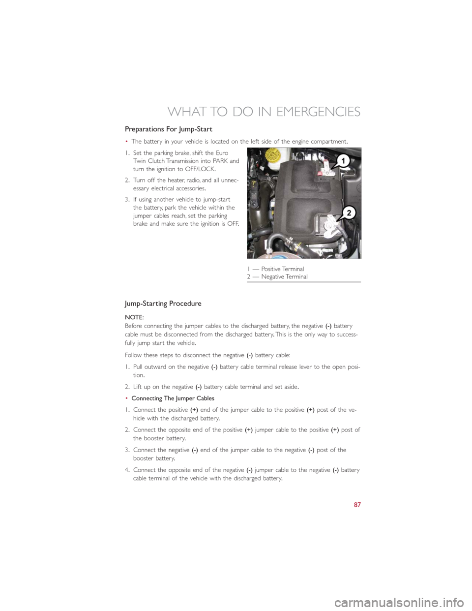
•The battery in your vehicle is located on the left side of the engine compartment.
1.Set the parking brake, shift the Euro
Twin Clutch Transmission into PARK and
turn the ignition to OFF/LOCK.
2.Turn off the heater, radio, and all unnec-
essary electrical accessories.
3.If using another vehicle to jump-start
the battery, park the vehicle within the
jumper cables reach, set the parking
brake and make sure the ignition is OFF.
Jump-Starting Procedure
NOTE:
Before connecting the jumper cables to the discharged battery, the negative(-)battery
cable must be disconnected from the discharged battery.This is the only way to success-
fully jump start the vehicle.
Follow these steps to disconnect the negative(-)battery cable:
1.Pull outward on the negative(-)battery cable terminal release lever to the open posi-
tion.
2.Lift up on the negative(-)battery cable terminal and set aside.
•Connecting The Jumper Cables
1.Connect the positive(+)end of the jumper cable to the positive(+)post of the ve-
hicle with the discharged battery.
2.Connect the opposite end of the positive(+)jumper cable to the positive(+)post of
the booster battery.
3.Connect the negative(-)end of the jumper cable to the negative(-)post of the
booster battery.
4.Connect the opposite end of the negative(-)jumper cable to the negative(-)battery
cable terminal of the vehicle with the discharged battery.
1 — Positive Terminal
2 — Negative Terminal
WHAT TO DO IN EMERGENCIES
87
Page 92 of 116
TOWING A DISABLED VEHICLE
With Ignition Key
Euro Twin Clutch Transmission
•Vehicle can be towed with the front wheels elevated.
•Vehicle can be towed on a flatbed truck (all wheels off the ground).
Manual Transmission
•Vehicle can be flat towed (all four wheels on the ground) with the transmission in
NEUTRAL.
•Vehicle can be towed with the front wheels elevated.
•Vehicle can be towed on a flatbed truck (all wheels off the ground).
NOTE:
If it is necessary to use the accessories while being towed (wipers, defrosters, etc.),
the key must be in the ON/RUN position.Make certain the transmission remains in
NEUTRAL.
All Transmissions
•If it is necessary to use the accessories while being towed (wipers, defrosters, etc.),
the key must be in the ON/RUN position.Make certain the transmission remains in
NEUTRAL.
Without The Ignition Key
•Special care must be taken when the vehicle is towed with the ignition in the OFF/
LOCK position.A dolly should be used under the front wheels if the rear wheels are
raised.Proper towing equipment is necessary to prevent damage to the vehicle.
•Battery power is required to release the brake/transmission interlock system (Euro
Twin Clutch Transmission only).There is a removable plug in the right side of the shift
lever housing that allows you to override the system.Refer to Shift Lever Override in
this guide.
CAUTION!
•Failure to follow these towing methods can cause severe transmission damage.
Such damage is not covered by the New Vehicle Limited Warranty.
•DO NOT flat tow any vehicle equipped with a Euro Twin Clutch Transmission.
Damage to the drivetrain will result.
•If the vehicle being towed requires steering, the ignition switch must be in the
ON/RUN position.
•Do not attempt to use sling-type equipment when towing.When securing the
vehicle to a flatbed truck, do not attach to front or rear suspension components.
Damage to your vehicle may result from improper towing.
WHAT TO DO IN EMERGENCIES
90
Page 95 of 116
OPENING THE HOOD
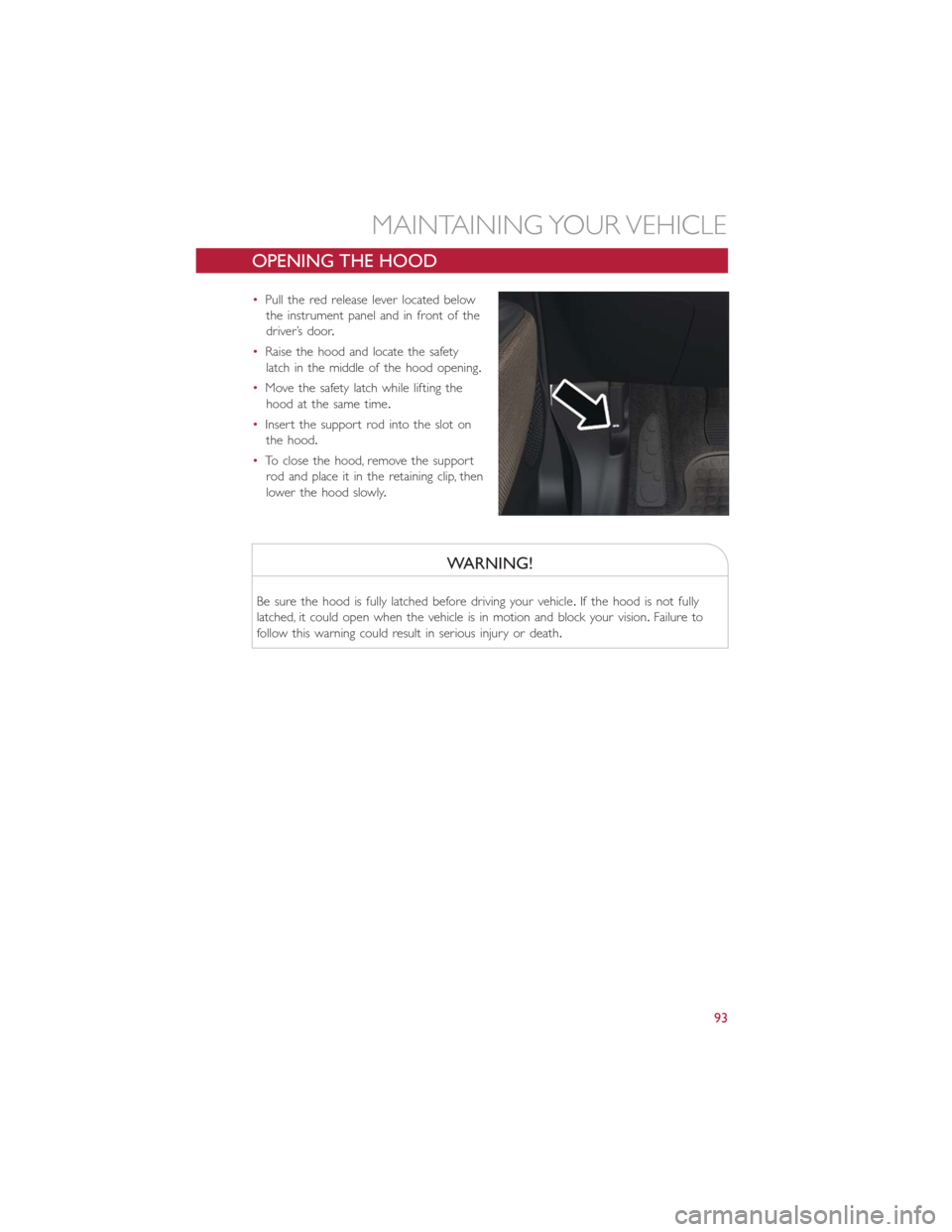
•Pull the red release lever located below
the instrument panel and in front of the
driver’s door.
•Raise the hood and locate the safety
latch in the middle of the hood opening.
•Move the safety latch while lifting the
hood at the same time.
•Insert the support rod into the slot on
the hood.
•To close the hood, remove the support
rod and place it in the retaining clip, then
lower the hood slowly.
WARNING!
Be sure the hood is fully latched before driving your vehicle.If the hood is not fully
latched, it could open when the vehicle is in motion and block your vision.Failure to
follow this warning could result in serious injury or death.
MAINTAINING YOUR VEHICLE
93
Page 102 of 116
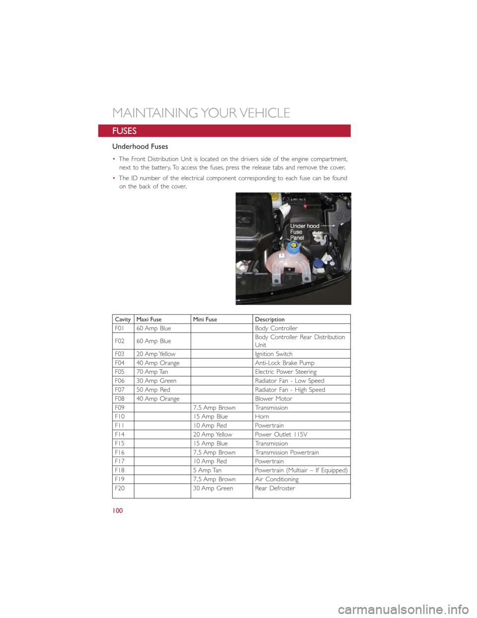
FUSES
Underhood Fuses
•The Front Distribution Unit is located on the drivers side of the engine compartment,
next to the battery.To access the fuses, press the release tabs and remove the cover.
•The ID number of the electrical component corresponding to each fuse can be found
on the back of the cover.
Cavity Maxi Fuse Mini Fuse Description
F01 60 Amp Blue Body Controller
F02 60 Amp BlueBody Controller Rear Distribution
Unit
F03 20 Amp Yellow Ignition Switch
F04 40 Amp Orange Anti-Lock Brake Pump
F05 70 Amp Tan Electric Power Steering
F06 30 Amp Green Radiator Fan - Low Speed
F07 50 Amp Red Radiator Fan - High Speed
F08 40 Amp Orange Blower Motor
F09 7.5 Amp Brown Transmission
F10 15 Amp Blue Horn
F11 10 Amp Red Powertrain
F14 20 Amp Yellow Power Outlet 115V
F15 15 Amp Blue Transmission
F16 7.5 Amp Brown Transmission Powertrain
F17 10 Amp Red Powertrain
F18 5 Amp Tan Powertrain (Multiair – If Equipped)
F19 7.5 Amp Brown Air Conditioning
F20 30 Amp Green Rear Defroster
MAINTAINING YOUR VEHICLE
100
Page 103 of 116
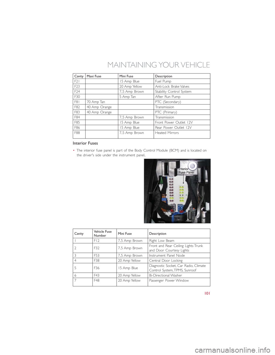
Cavity Maxi Fuse Mini Fuse Description
F21 15 Amp Blue Fuel Pump
F23 20 Amp Yellow Anti-Lock Brake Valves
F24 7.5 Amp Brown Stability Control System
F30 5 Amp Tan After Run Pump
F81 70 Amp Tan PTC (Secondary)
F82 40 Amp Orange Transmission
F83 40 Amp Orange PTC (Primary)
F84 7.5 Amp Brown Transmission
F85 15 Amp Blue Front Power Outlet 12V
F86 15 Amp Blue Rear Power Outlet 12V
F88 7.5 Amp Brown Heated Mirrors
Interior Fuses
•The interior fuse panel is part of the Body Control Module (BCM) and is located on
the driver's side under the instrument panel.
CavityVehicle Fuse
NumberMini Fuse Description
1 F12 7.5 Amp Brown Right Low Beam
2 F32 7.5 Amp BrownFront and Rear Ceiling Lights Trunk
and Door Courtesy Lights
3 F53 7.5 Amp Brown Instrument Panel Node
4 F38 20 Amp Yellow Central Door Locking
5 F36 15 Amp BlueDiagnostic Socket, Car Radio, Climate
Control System, TPMS, Sunroof
6 F43 20 Amp Yellow Bi-Directional Washer
7 F48 20 Amp Yellow Passenger Power Window
MAINTAINING YOUR VEHICLE
101