air condition FIAT 500L 2015 2.G User Guide
[x] Cancel search | Manufacturer: FIAT, Model Year: 2015, Model line: 500L, Model: FIAT 500L 2015 2.GPages: 148, PDF Size: 3.77 MB
Page 15 of 148
•The ORC turns on the Air Bag Warning Light in the instrument panel for approxi-
mately four to eight seconds for a self-check when the ignition switch is first turned to
the ON/RUN position.After the self-check, the Air Bag Warning Light will turn off.If
the ORC detects a malfunction in any part of the system, it turns on the Air Bag
Warning Light, either momentarily or continuously.A single chime will sound to alert
you if the light comes on again after initial startup.
•The ORC monitors the readiness of the electronic parts of the air bag system when-
ever the ignition switch is in the START or ON/RUN position.If the ignition switch is
in the OFF position or in the ACC position, the air bag system is not on and the air
bags will not inflate.
•If the Air Bag Warning Light in the instrument panel is not on during the four to eight
seconds when the ignition switch is first turned to the ON/RUN position, stays on, or
turns on while driving, have the vehicle serviced by an authorized service center imme-
diately.
NOTE:
If the speedometer, tachometer, or any engine related gauges are not working, the Occu-
pant Restraint Controller (ORC) may also be disabled.In this condition the air bags may
not be ready to inflate for your protection.Have an authorized dealer service the air bag
system immediately.
•After any collision, the vehicle should be taken to an authorized dealer immediately.
•Do not drive your vehicle after the air bags have deployed.If you are involved in an-
other collision, the air bags will not be in place to protect you.
•If it is necessary to modify the air bag system for persons with disabilities, contact your
authorized dealer.
•Refer to “Supplemental Restraint System (SRS)” in “Things To Know Before Starting
Your Vehicle” in the Owner's Manual on the DVD for further information.
Supplemental Knee Air Bags
This vehicle is equipped with a Supplemental Driver Knee Air Bag mounted in the instru-
ment panel below the steering column.The Supplemental Driver Knee Air Bag provides
enhanced protection during a frontal impact by working together with the seat belts, pre-
tensioners, and Advanced Front Air Bags.
GETTING STARTED
13
Page 95 of 148
Tire Pressure Monitoring System (TPMS) Light
Each tire, including the spare (if provided), should be checked monthly when cold and
inflated to the inflation pressure recommended by the vehicle manufacturer on the ve-
hicle placard or tire inflation pressure label.(If your vehicle has tires of a different size
than the size indicated on the vehicle placard or tire inflation pressure label, you should
determine the proper tire inflation pressure for those tires).
As an added safety feature, your vehicle has been equipped with a tire pressure monitor-
ing system (TPMS) that illuminates a low tire pressure telltale when one or more of your
tires is significantly under-inflated.Accordingly, when the low tire pressure telltale illumi-
nates, you should stop and check your tires as soon as possible and inflate them to the
proper pressure.Driving on a significantly under-inflated tire causes the tire to overheat
and can lead to tire failure.Under-inflation also reduces fuel efficiency and tire tread life
and may affect the vehicle’s handling and stopping ability.
IF THE LIGHT STARTS FLASHING INDICATING A LOW TIRE PRESSURE, ADJUST
THE AIR PRESSURE IN THE LOW TIRE TO THE AIR PRESSURE SHOWN ON THE
VEHICLE PLACARD OR TIRE INFLATION PRESSURE LABEL LOCATED ON THE
DRIVER'S DOOR.
NOTE:
AFTER INFLATION, THE VEHICLE MAY NEED TO BE DRIVEN FOR 20 MINUTES BE-
FORE THE FLASHING LIGHT WILL TURN OFF.
Please note that the TPMS is not a substitute for proper tire maintenance, and it is the
driver’s responsibility to maintain correct tire pressure, even if under-inflation has not
reached the level to trigger illumination of the TPMS low tire pressure telltale.
Your vehicle has also been equipped with a TPMS malfunction indicator to indicate when
the system is not operating properly.The TPMS malfunction indicator is combined with
the low tire pressure telltale.
When the system detects a malfunction, the telltale will flash for approximately one min-
ute and then remain continuously illuminated.This sequence will continue upon subse-
quent vehicle start-ups as long as the malfunction exists.When the malfunction indicator
is illuminated, the system may not be able to detect or signal low tire pressure as in-
tended.TPMS malfunctions may occur for a variety of reasons, including the installation of
replacement or alternate tires or wheels on the vehicle that prevent the TPMS from
functioning properly.Always check the TPMS malfunction telltale after replacing one or
more tires or wheels on your vehicle to ensure that the replacement or alternate tires
and wheels allow the TPMS to continue to function properly.
NOTE:
Tire pressures change by approximately 1 psi (7 kPa) per 12° F (7° C) of air tempera-
ture change.Keep this in mind when checking tire pressure inside a garage, especially in
the Winter.Example: If garage temperature is 68°F (20°C), and the outside temperature
is 32°F (0°C), then the cold tire inflation pressure should be increased by 3 psi (21 kPa),
which equals 1 psi (7 kPa) for every 12°F (7°C) for this outside temperature condition.
WHAT TO DO IN EMERGENCIES
93
Page 97 of 148
Anti-Lock Brake System (ABS)/Electronic Stability Control (ESC) system.In this case, the
light will remain on until the condition has been corrected.If the problem is related to
the brake booster, the ABS pump will run when applying the brake, and a brake pedal
pulsation may be felt during each stop.
The dual brake system provides a reserve braking capacity in the event of a failure to a
portion of the hydraulic system.A leak in either half of the dual brake system is indicated
by the Brake Warning Light, which will turn on when the brake fluid level in the master
cylinder has dropped below a specified level.The light will remain on until the cause is
corrected.
Vehicles equipped with the Anti-Lock Brake System (ABS) are also equipped with Elec-
tronic Brake Force Distribution (EBD).In the event of an EBD failure, the Brake Warning
Light will turn on along with the ABS Light.Immediate repair to the ABS system is re-
quired.
Operation of the Brake Warning Light can be checked by turning the ignition switch from
the OFF position to the ON/RUN position.The light should illuminate for approximately
two seconds.The light should then turn off unless the parking brake is applied or a brake
fault is detected.If the light does not illuminate, have the light inspected by an authorized
dealer.
The light also will turn on when the parking brake is applied with the ignition switch in
the ON/RUN position.
NOTE:
This light shows only that the parking brake is applied.It does not show the degree of
brake application.
WARNING!
Driving a vehicle with the red brake light on is dangerous.Part of the brake system
may have failed.It will take longer to stop the vehicle.You could have a collision.Have
the vehicle checked immediately.
- Malfunction Indicator Light (MIL)
Certain conditions, such as a loose or missing gas cap, poor fuel quality, etc., may illumi-
nate the MIL after engine start.The vehicle should be serviced if the light stays on
through several typical driving cycles.In most situations, the vehicle will drive normally and
not require towing.
If the MIL flashes when the engine is running, serious conditions may exist that could lead
to immediate loss of power or severe catalytic converter damage.We recommend you
do not operate the vehicle.Have the vehicle serviced immediately.
WHAT TO DO IN EMERGENCIES
95
Page 100 of 148
Change Engine Oil
•Your vehicle is equipped with an engine oil change indicator system.The “Change En-
gine Oil” message will flash in the EVIC display for approximately 10 seconds after a
single chime has sounded to indicate the next scheduled oil change interval.The engine
oil change indicator system is duty cycle based, which means the engine oil change in-
terval may fluctuate, dependent upon your personal driving style.
•Unless reset, this message will continue to display each time you turn the ignition
switch to the ON/RUN position.To turn off the message temporarily, press and re-
lease theMENUbutton.To reset the oil change indicator system (after performing the
scheduled maintenance), refer to the following procedure:
1.Turn the ignition switch to the ON position.(do not start the engine).
2.Fully depress the accelerator pedal slowly, three times within 10 seconds.
3.Turn the ignition switch to the OFF/LOCK position.
NOTE:
If the indicator message illuminates when you start the vehicle, the oil change indicator
system did not reset.If necessary, repeat this procedure.
IF YOUR ENGINE OVERHEATS
In any of the following situations, you can reduce the potential for overheating by taking
the appropriate action:
•On the highways — slow down.
•In city traffic — while stopped, shift transmission into NEUTRAL, but do not increase
engine idle speed.
NOTE:
There are steps that you can take to slow down an overheat condition:
•If your air conditioner (A/C) is on, turn it off.The A/C system adds heat to the engine
cooling system and turning the A/C off can help remove this heat.
•You can also turn the Temperature control to maximum heat, the Mode control to
floor and the Fan control to high.This allows the heater core to act as a supplement
to the radiator and aids in removing heat from the engine cooling system.
•If the temperature reading does not return to normal, turn the engine off immediately.
•We recommend that you do not operate the vehicle or engine damage will occur.
Have the vehicle serviced immediately.
WHAT TO DO IN EMERGENCIES
98
Page 101 of 148
CAUTION!
Driving with a hot cooling system could damage your vehicle.If the temperature gauge
reads hot, pull over and stop the vehicle.Idle the vehicle with the air conditioner
turned off until the pointer drops back into the normal range.If the pointer remains
on hot, turn the engine off immediately and call for service.
WARNING!
You or others can be badly burned by hot engine coolant (antifreeze) or steam from
your radiator.If you see or hear steam coming from under the hood, do not open the
hood until the radiator has had time to cool.Never try to open a cooling system pres-
sure cap when the radiator or coolant bottle is hot.
JACKING AND TIRE CHANGING
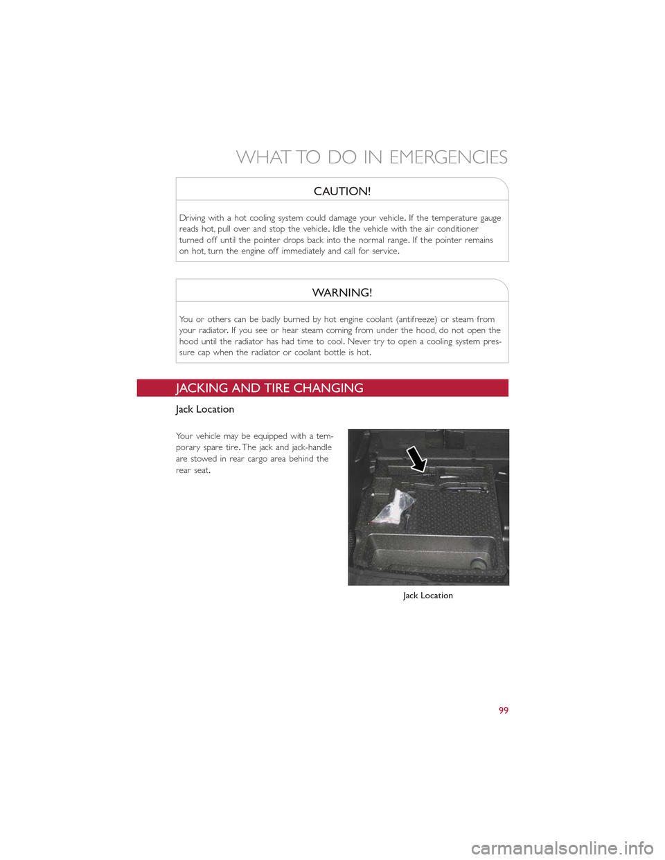
Jack Location
Your vehicle may be equipped with a tem-
porary spare tire.The jack and jack-handle
are stowed in rear cargo area behind the
rear seat.
Jack Location
WHAT TO DO IN EMERGENCIES
99
Page 114 of 148
WARNING!
•Do not attempt to seal a tire on the side of the vehicle closest to traffic.Pull far
enough off the road to avoid the danger of being hit when using the Tire Service
Kit.
•Do not use the Tire Service Kit or drive the vehicle under the following circum-
stances:
•If the puncture in the tire tread is approximately 1/4”.(6 mm) or larger.
•If the tire has any sidewall damage.
•If the tire has any damage from driving with extremely low tire pressure.
•If the tire has any damage from driving on a flat tire.
•If the wheel has any damage.
•If you are unsure of the condition of the tire or the wheel.
•Keep the Tire Service Kit away from open flames or heat source.
•A loose Tire Service Kit thrown forward in a collision or hard stop could endanger
the occupants of the vehicle.Always stow the Tire Service Kit in the place pro-
vided.Failure to follow these warnings can result in injuries that are serious or
fatal to you, your passengers, and others around you.
•Take care not to allow the contents of the Tire Service Kit to come in contact
with hair, eyes, or clothing.The Tire Service Kit is harmful if inhaled, swallowed, or
absorbed through the skin.It causes skin, eye, and respiratory irritation.Flush im-
mediately with plenty of water if there is any contact with eyes or skin.Change
clothing as soon as possible, if there is any contact with clothing.
•The Tire Service Kit Sealant solution contains latex.In case of an allergic reaction
or rash, consult a physician immediately.Keep the Tire Service Kit out of reach of
children.If swallowed, rinse mouth immediately with plenty of water and drink
plenty of water.Do not induce vomiting! Consult a physician immediately.
•The Tire Service Kit is not a permanent flat tire repair.Have the tire inspected
and repaired or replaced after using the Tire Service Kit.Do not exceed 55 mph
(88 km/h) until the tire is repaired or replaced.Failure to follow this warning can
result in injuries that are serious or fatal to you, your passengers, and others
around you.
WHAT TO DO IN EMERGENCIES
112
Page 122 of 148
EVENT DATA RECORDER (EDR)
This vehicle is equipped with an Event Data Recorder (EDR).The main purpose of an
EDR is to record, in certain crash or near crash-like situations, such as an air bag deploy-
ment or hitting a road obstacle, data that will assist in understanding how a vehicle’s sys-
tems performed.The EDR is designed to record data related to vehicle dynamics and
safety systems for a short period of time, typically 30 seconds or less.The EDR in this
vehicle is designed to record such data as:
•How various systems in your vehicle were operating.
•Whether or not the driver and passenger safety belts were buckled/fastened.
•How far (if at all) the driver was depressing the accelerator and/or brake pedal.
•How fast the vehicle was traveling.
These data can help provide a better understanding of the circumstances in which
crashes and injuries occur.
NOTE:
EDR data is recorded by your vehicle only if a non-trivial crash situation occurs; no data
is recorded by the EDR under normal driving conditions and no personal data (e.g.
name, gender, age, and crash location) is recorded.However, other parties, such as law
enforcement, could combine the EDR data with the type of personally identifying data
routinely acquired during a crash investigation.
To read data recorded by an EDR, special equipment is required, and access to the ve-
hicle or the EDR is needed.In addition to the vehicle manufacturer, other parties such as
law enforcement, that have the special equipment, can read the information if they have
access to the vehicle or the EDR.
CAP-LESS FUEL FILL FUNNEL
•The funnel for the Cap-Less Fuel System is located in the rear cargo area behind the
rear seat.If your vehicle is out of fuel and an auxiliary fuel can is needed, insert the
funnel into the filler neck and proceed to fill the vehicle.
•For more information on the Cap-Less Fuel Fill Funnel refer to “Adding Fuel” in “Oper-
ating Your Vehicle” in this manual.
WHAT TO DO IN EMERGENCIES
120
Page 129 of 148
Required Maintenance Intervals.
Refer to the maintenance schedules on the following page for the required maintenance
intervals.
At Every Oil Change Interval As Indicated By Oil Change Indicator System:
•Change oil and filter.
•Rotate the tires.Rotate at the first sign of irregular wear, even if it occurs before the oilindicator system turns on.
•Inspect battery and clean and tighten terminals as required.
•Inspect brake pads, shoes, rotors, drums, and hoses.
•Inspect engine cooling system protection and hoses.
•Check and adjust hand brake.
•Inspect exhaust system.
•Inspect engine air cleaner if using in dusty or off-road conditions.
MAINTAINING YOUR VEHICLE
127
Page 132 of 148
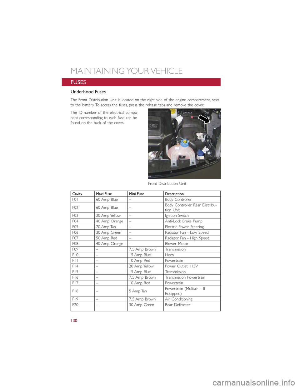
FUSES
Underhood Fuses
The Front Distribution Unit is located on the right side of the engine compartment, next
to the battery.To access the fuses, press the release tabs and remove the cover.
The ID number of the electrical compo-
nent corresponding to each fuse can be
found on the back of the cover.
Cavity Maxi Fuse Mini Fuse Description
F01 60 Amp Blue – Body Controller
F02 60 Amp Blue –Body Controller Rear Distribu-tion Unit
F03 20 Amp Yellow – Ignition Switch
F04 40 Amp Orange – Anti-Lock Brake Pump
F05 70 Amp Tan – Electric Power Steering
F06 30 Amp Green – Radiator Fan - Low Speed
F07 50 Amp Red – Radiator Fan - High Speed
F08 40 Amp Orange – Blower Motor
F09 – 7.5 Amp Brown Transmission
F10 – 15 Amp Blue Horn
F11 – 10 Amp Red Powertrain
F14 – 20 Amp Yellow Power Outlet 115V
F15 – 15 Amp Blue Transmission
F16 – 7.5 Amp Brown Transmission Powertrain
F17 – 10 Amp Red Powertrain
F18 – 5 Amp TanPowertrain (Multiair – IfEquipped)
F19 – 7.5 Amp Brown Air Conditioning
F20 – 30 Amp Green Rear Defroster
Front Distribution Unit
MAINTAINING YOUR VEHICLE
130
Page 143 of 148
Adding Engine Coolant (Antifreeze)....126
Adding Fuel.................37
Adding Washer Fluid............126
Air Bag
Advanced Front Air Bag.........12
Advance Front Air Bag.........12
Air Bags.................12
Air Bag Warning Light..........12
Driver Knee Air Bag...........13
Front Air Bag..............12Passenger Knee Air Bag.........13Rollover.................12Side Impacts...............12Air Bag Light.................92Air Bag, Side.................12Air Cleaner, Engine (Engine AirCleaner Filter).............126Air Conditioner Maintenance.......126Air Conditioning Refrigerant........126Air Conditioning System..........126AlarmDisarm The System............9Vehicle Security Alarm..........9Alarm (Security Alarm)..........9, 97Antifreeze (Engine Coolant).....124, 126Capacities...............124Disposal................126Anti-Lock Warning Light...........92Appearance Care.............126Audio Systems (Radio).........41, 45Automatic TransmissionFluid Type...............125
Battery...................126Body Mechanism Lubrication........126Brake Fluid.................125Brakes...................126Brake System................126Master Cylinder............126Warning Light..............94Break-In Recommendations, New Vehicle..26Bulb Replacement.............136Bulbs, Light.................136
Capacities, Antifreeze (Engine Coolant)..124Capacities, Fluid...............124Caps, FillerFuel..................120
Oil (Engine)..............126
Car Washes................126
Changing A Flat Tire.............99
Charging System Light............92
Child Restraint................15
Child Restraints
Center Seat LATCH...........16
Installing Child Restraints Using The
Vehicle Seat Belt.............17
Lower Anchors And Tethers ForChildren.................17Using The Top Tether Anchorage....17CleaningWheels................126Windshield Wiper Blades.......126Climate ControlAutomatic................32Manual..................31Clock....................43Clock Setting................43Cluster Warning/Indicator LightsAnti-Lock Brake (ABS) Light......92Brake Warning Light...........94Charging System Light.........92Electronic Speed Control SETIndicator.................97Electronic Throttle Control (ETC)Indicator Light..............96Engine Temperature Warning Light...94Front Fog Light Indicator........97High Beam Indicator..........96Malfunction Indicator Light (MIL)....95Oil Pressure Warning Light.......92Park/Headlight ON Indicator......97Tire Pressure Monitoring System(TPMS) Light..............93Turn Signal Indicator..........96Vehicle Security Light..........97Clutch...................126Clutch Fluid................126Compact Spare Tire............134Coolant (Antifreeze)............124Cooling System...............126Adding Coolant (Antifreeze).....126Coolant Level.............126Disposal Of Used Coolant......126Drain, Flush, And Refill.........126Inspection...............126
INDEX
141