tow FIAT 500L 2019 Owner handbook (in English)
[x] Cancel search | Manufacturer: FIAT, Model Year: 2019, Model line: 500L, Model: FIAT 500L 2019Pages: 248, PDF Size: 5.74 MB
Page 124 of 248
IN AN EMERGENCY
A punctured tyre or a burnt-out bulb?
At times, a problem may interfere
with our journey.
The pages on emergencies can help
you to deal with critical situations
independently and with calm.
In an emergency we recommend that
you call the freephone number found in
the Warranty Booklet.
It is also possible to call the national or
international universal freephone
number to search for the nearest
Dealership.HAZARD WARNING LIGHTS...........123
REPLACING A WHEEL ...................123
“FIX&GO AUTOMATIC” KIT .............128
CHANGING A BULB .......................130
REPLACING FUSES........................138
JUMP STARTING ............................144
FUEL CUT-OFF SYSTEM ................146
TOWING THE VEHICLE ..................146
122
IN AN EMERGENCY
Page 127 of 248
alert any bystander that the car is
about to be raised; all persons should
be kept away from the car and nobody
must touch it until it has been lowered;
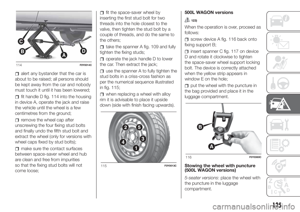
fit handle D fig. 114 into the housing
in device A, operate the jack and raise
the vehicle until the wheel is a few
centimetres from the ground;
remove the wheel cap after
unscrewing the four fixing stud bolts
and finally undo the fifth stud bolt and
extract the wheel (only for versions with
wheel caps fixed by stud bolts);
make sure the contact surfaces
between space-saver wheel and hub
are clean and free from impurities
so that the fixing stud bolts will not
come loose;
fit the space-saver wheel by
inserting the first stud bolt for two
threads into the hole closest to the
valve, then tighten the stud bolt by a
couple of threads, and do the same to
the others;
take the spanner A fig. 109 and fully
tighten the fixing studs;
operate the jack handle D to lower
the car. Then extract the jack;
use the spanner A to fully tighten the
stud bolts in a criss-cross fashion as
per the numerical sequence illustrated
in fig. 115;
when replacing a wheel with alloy
rim it is advisable to place it upside
down (side with finish facing upwards).500L WAGON versions
123)
When the operation is over, proceed as
follows:
screw device A fig. 116 back onto
fixing support B;
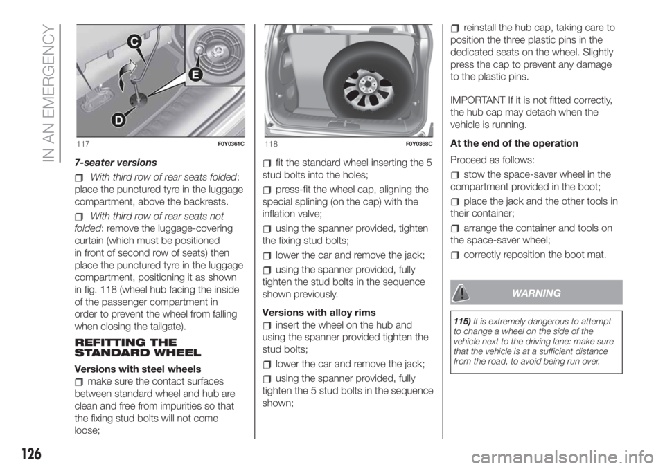
insert spanner C fig. 117 on device
D and rotate it clockwise to tighten
the space-saver wheel support locking
bolt. The device is correctly attached
when the yellow strip appears in
window E on the hole;
put the wheel with the puncture in
the bag provided and place it in the
luggage compartment.
Stowing the wheel with puncture
(500L WAGON versions)
5-seater versions: place the wheel with
the puncture in the luggage
compartment.
114F0Y0014C
115F0Y0013C
116F0Y0360C
125
Page 128 of 248
7-seater versions
With third row of rear seats folded:
place the punctured tyre in the luggage
compartment, above the backrests.
With third row of rear seats not
folded: remove the luggage-covering
curtain (which must be positioned
in front of second row of seats) then
place the punctured tyre in the luggage
compartment, positioning it as shown
in fig. 118 (wheel hub facing the inside
of the passenger compartment in
order to prevent the wheel from falling
when closing the tailgate).
REFITTING THE
STANDARD WHEEL
Versions with steel wheels
make sure the contact surfaces
between standard wheel and hub are
clean and free from impurities so that
the fixing stud bolts will not come
loose;
fit the standard wheel inserting the 5
stud bolts into the holes;
press-fit the wheel cap, aligning the
special splining (on the cap) with the
inflation valve;
using the spanner provided, tighten
the fixing stud bolts;
lower the car and remove the jack;
using the spanner provided, fully
tighten the stud bolts in the sequence
shown previously.
Versions with alloy rims
insert the wheel on the hub and
using the spanner provided tighten the
stud bolts;
lower the car and remove the jack;
using the spanner provided, fully
tighten the 5 stud bolts in the sequence
shown;
reinstall the hub cap, taking care to
position the three plastic pins in the
dedicated seats on the wheel. Slightly
press the cap to prevent any damage
to the plastic pins.
IMPORTANT If it is not fitted correctly,
the hub cap may detach when the
vehicle is running.
At the end of the operation
Proceed as follows:
stow the space-saver wheel in the
compartment provided in the boot;
place the jack and the other tools in
their container;
arrange the container and tools on
the space-saver wheel;
correctly reposition the boot mat.
WARNING
115)It is extremely dangerous to attempt
to change a wheel on the side of the
vehicle next to the driving lane: make sure
that the vehicle is at a sufficient distance
from the road, to avoid being run over.
117F0Y0361C118F0Y0368C
126
IN AN EMERGENCY
Page 130 of 248
“Fix&Go Automatic”
KIT
124) 125)52)2)
DESCRIPTION
The Fix&Go Automatic kit is located in
the luggage compartment, inside a
dedicated container. The container is
also equipped with a screwdriver,
the tow hook and the funnel for
refuelling in an emergency. To access
the kit, open the luggage compartment
door, remove the load platform and
lift the covering carpet.
REPAIR PROCEDURE
Proceed as follows:
stop the car in a position that is not
dangerous for oncoming traffic where
you can change the wheel safely. The
car must be stopped in a lay-by,
car-park or parking or service area, and
the ground must be as level as possible
and sufficiently compact;
switch off the engine, pull up the
handbrake and engage the 1stgear or
reverse. Make sure that any passengers
get out of the car and go to a safe
place where they will not obstruct traffic
or be exposed to the risk of injury.
Wear the reflective safety jacket
(compulsory by law) before getting out
of the car;
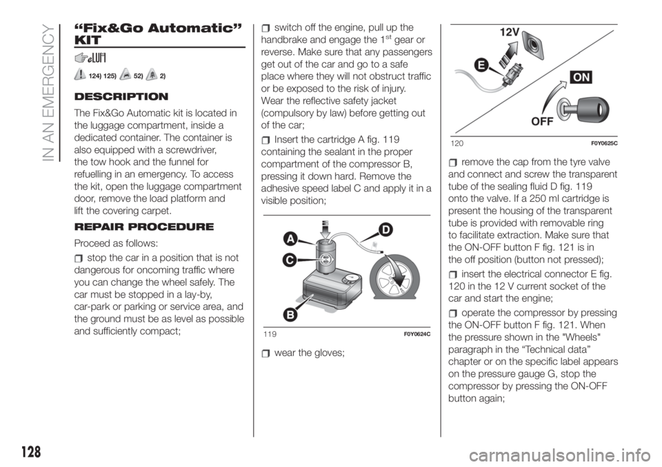
Insert the cartridge A fig. 119
containing the sealant in the proper
compartment of the compressor B,
pressing it down hard. Remove the
adhesive speed label C and apply it in a
visible position;
wear the gloves;
remove the cap from the tyre valve
and connect and screw the transparent
tube of the sealing fluid D fig. 119
onto the valve. If a 250 ml cartridge is
present the housing of the transparent
tube is provided with removable ring
to facilitate extraction. Make sure that
the ON-OFF button F fig. 121 is in
the off position (button not pressed);
insert the electrical connector E fig.
120 in the 12 V current socket of the
car and start the engine;
operate the compressor by pressing
the ON-OFF button F fig. 121. When
the pressure shown in the "Wheels"
paragraph in the “Technical data”
chapter or on the specific label appears
on the pressure gauge G, stop the
compressor by pressing the ON-OFF
button again;
119F0Y0624C
120F0Y0625C
128
IN AN EMERGENCY
Page 133 of 248
IMPORTANT When the weather is cold
or damp or after heavy rain or washing,
the surface of headlights or rear lights
may steam up and/or form drops of
condensation on the inside. This is
a natural phenomenon due to the
difference in temperature and humidity
between the inside and the outside
of the glass which does not indicate a
fault and does not compromise the
normal operation of lighting devices.
The mist disappears quickly when the
lights are turned on, starting from
the centre of the diffuser, extending
progressively towards the edges.
131
Page 142 of 248
ACCESS TO DASHBOARD
FUSES (right-hand drive
version)
To access the fuses, proceed as
follows:
open the passenger side lower glove
compartment;
using the supplied screwdriver fig.
151 remove the two side devices A fig.
152;
press on the devices B fig. 153 at
the sides of the glove compartment;
remove the guard C fig. 154, pulling
it towards you. This gives access to
the fusebox fig. 155 and the faulty fuse
can now be replaced.
After changing the faulty fuse, replace
the guard C and perform the sequence
of operations described above, in
reverse order.Take particular care to fit the devices B
correctly.
151F0Y0236C
152F0Y0235C
153F0Y0238C
154F0Y0239C
155F0Y0237C
140
IN AN EMERGENCY
Page 147 of 248
disconnect the other end of the
cable used for negative (–) from the
negative terminal (–) of the auxiliary
battery;
disconnect the end of the cable
used for positive (+) from the positive
terminal (+) of the auxiliary battery;
disconnect one end of the cable
used for positive (+) from the positive
terminal (+) of the car with flat battery.
If it is often necessary to perform a
jump starting, have the car battery and
the recharging system checked by a
Fiat Dealership.
BUMP STARTING
Never, under any circumstances, jump
start the engine by pushing, towing
or coasting downhill.
IMPORTANT Remember that the brake
servo and electric power steering are
not active until the engine is started. A
much greater effort will therefore be
required to use the brake pedal or turn
the steering wheel.IMPORTANT Any accessories (e.g.
mobile phones, etc.) connected to the
vehicle power sockets draw current
even if they are not used. These
devices, if left connected too much time
with engine off, may cause the battery
to drain with following reduction of
its life and/or failure to start the engine.
WARNING
136)Do not get too close to the radiator
cooling fan: the electric fan may start;
danger of injury. Scarves, ties and other
loose clothing might be pulled by moving
parts.
137)Remove any metal objects (e.g. rings,
watches, bracelets), that might cause an
accidental electrical contact and cause
serious injury.
138)The batteries contain acid that can
burn skin or eyes. Batteries produce
hydrogen, which is easily flammable and
explosive. Thus keep away flames or
devices which may cause sparks.
139)This starting procedure must be
performed by expert personnel because
incorrect actions could cause electrical
discharge of considerable intensity.
Furthermore, battery fluid is poisonous and
corrosive: avoid contact with skin and
eyes. Keep naked flames and lighted
cigarettes away from the battery and do
not cause sparks.
WARNING
56)Do not connect the cable to the
negative terminal (–) of the flat battery. The
following spark could lead to battery
explosion and cause serious harm. Only
use the specific earth point; do not use any
other exposed metallic part.
57)Never use a fast battery-charger to
start the engine as this could damage the
electronic systems of your vehicle,
particularly the ignition and engine fuel
supply control units.
145
Page 148 of 248
FUEL CUT-OFF
SYSTEM
140)
This intervenes in the case of an impact
causing:
the interruption of the fuel supply
with the engine consequently cutting
out;
the automatic unlocking of the
doors;
turning on the lights inside the car;
the switching on of the hazard
warning lights.
The intervention of the system is
indicated by a message shown on the
display.
IMPORTANT Carefully check the car for
fuel leaks, for instance in the engine
compartment, under the car or near the
tank area. After an impact, turn the
ignition key to STOP to prevent the
battery from running down.
Reset procedure
To restore correct operation of the
system, carry out the following Reset
procedure (the procedure must be
completed in less than 1 minute):
turn the ignition key to the MAR
position;
activate the right direction indicator
and then stop it;
activate the left direction indicator
and then stop it;
activate the right direction indicator
and then stop it;
activate the left direction indicator
and then stop it;
turn the ignition key to the STOP
position and then to MAR.
WARNING
140)If, after an impact, you smell fuel or
notice leaks from the fuel system, do
not reactivate the system to avoid the risk
of fire.
TOWING THE
VEHICLE
ATTACHING THE TOW
RING
141) 142) 143) 144)
The tow rings, which are supplied with
the car, are housed in the tool box,
under the carpet in the luggage
compartment.
IMPORTANT The shorter tow ring is for
use on the front of the car and the
longer one on the rear.
500L WAGON versions
NOTE 500L WAGON versions have
only one tow ring, which can be used
on either the front or the rear bumper.
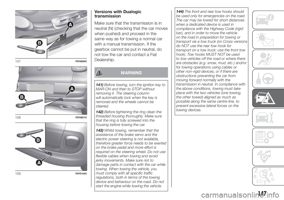
Front
Manually remove cap A fig. 157,
pressing in the lower part. Take tow ring
B from its housing in the tool support
and screw it completely onto the
threaded pin.
Rear
Manually remove cap A fig. 158 or fig.
159 (500L WAGON versions) by
pressing at the bottom. Take tow ring B
from its housing in the tool support
and screw it completely onto the
threaded pin.
146
IN AN EMERGENCY
Page 149 of 248
Versions with Dualogic
transmission
Make sure that the transmission is in
neutral (N) (checking that the car moves
when pushed) and proceed in the
same way as for towing a normal car
with a manual transmission. If the
gearbox cannot be put in neutral, do
not tow the car and contact a Fiat
Dealership.
WARNING
141)Before towing, turn the ignition key to
MAR-ON and then to STOP without
removing it. The steering column
will automatically lock when the key is
removed and the wheels cannot be
steered.
142)Before tightening the ring clean the
threaded housing thoroughly. Make sure
that the ring is fully screwed into the
housing before towing the car.
143)Whilst towing, remember that the
assistance of the brake servo and the
electric power steering is not available,
therefore greater force needs to be exerted
on the brake pedal and more effort is
required on the steering wheel. Do not use
flexible cables when towing and avoid
jerky movements. Make sure not to
damage parts in contact with the car while
towing. When towing the vehicle, you
must comply with all specific traffic
regulations, both in terms of the towing
device and behaviour on the road. Do not
start the engine while towing the vehicle.144)The front and rear tow hooks should
be used only for emergencies on the road.
The car may be towed for short distances
when a dedicated device is used in
compliance with the Highway Code (rigid
bar), and in order to move the vehicle
on the road in preparation for towing or
transport via a tow truck (on Cross versions
do NOT use the rear tow hook for
transport on a tow truck: use the front tow
hook). Tow hooks MUST NOT be used
to tow vehicles off the road or where there
are obstacles (e.g. snow, mud, etc.) and/or
for towing operations using cables or
other non-rigid devices, or if there are
obstructions preventing the car from
moving forward normally with the
transmission in neutral. In compliance with
the above conditions, towing must take
place with the two vehicles (one towing,
the other towed) aligned as much as
possible along the same centre line, to
prevent excessive lateral forces on the
towing devices.
157F0Y0630C
158F0Y0631C
159F0Y0144C
147
Page 151 of 248
SCHEDULED
SERVICING
Correct servicing is crucial for
guaranteeing a long life for the car
under the best conditions. For
this reason, Fiat has planned a series of
checks and services at fixed distance
and/or time intervals, as described
in the Service Schedule.
To keep the car in tip-top conditions, a
few additional checks which should
be carried out more frequently with
respect to the normal service deadlines
are listed in the Scheduled Service
plan on the previous pages.
IMPORTANT Scheduled Servicing
interventions are set out by the
Manufacturer. Failure to have them
carried out may invalidate the warranty.
We advise you to report any doubts
regarding the proper operation of the
car to your Fiat Dealership, before
waiting for the next service deadline.
REGULAR CHECKS
Every 1,000 kmor before long trips
check and, if necessary, top up:
engine coolant level;
brake fluid level;
AdBlue® (UREA) diesel emission
additive level (where present);
windscreen washer fluid level;
tyre inflation pressure and condition;
operation of lighting system
(headlights, direction indicators, hazard
warning lights, etc.);
operation of windscreen washer/
wiper system and positioning/wear of
rear window wiper blades.
Every3,000km, check and top up if
required: engine oil level.
DEMANDING USE OF THE
CAR
If the vehicle is used in one of the
following conditions:
law enforcement (or security
service), taxi service;
towing a trailer or caravan;
dusty roads;
short, repeated journeys (less than
7-8 Km) at sub-zero outdoor
temperatures;
engine often idling or driving long
distances at low speeds or long periods
of inactivity;
the following checks must be carried
out more often than indicated in the
Service Schedule:
check front disc brake pad condition
and wear;
check cleanliness of bonnet and
luggage compartment locks,
cleanliness and lubrication of linkage;
visually inspect conditions of:
engine, gearbox, transmission, pipes
and hoses (exhaust/fuel system/brakes)
and rubber elements (gaiters/sleeves/
bushes, etc.);
check battery charge and battery
fluid level (electrolyte);
visually inspect conditions of the
accessory drive belts;
check and, if necessary, change
engine oil and replace oil filter;
check and, if necessary, replace
pollen filter;
check and, if necessary, replace air
cleaner.
149