change wheel FIAT 500L 2019 Owner handbook (in English)
[x] Cancel search | Manufacturer: FIAT, Model Year: 2019, Model line: 500L, Model: FIAT 500L 2019Pages: 248, PDF Size: 5.74 MB
Page 7 of 248
SYMBOLS
Some car components have coloured labels whose symbols indicate precautions to be observed when using this component.
A plate summarising these symbols can also be found under the bonnet.
CHANGES/ALTERATIONS TO THE CAR
IMPORTANT Any change or alteration of the car might seriously affect its safety and road holding, thus causing accidents, in
which the occupants could even be fatally injured.
IMPORTANT The use of these devices inside the passenger compartment (without an external aerial) may cause the electrical
systems to malfunction. This could compromise the safety of the vehicle in addition to constituting a potential hazard for
passengers' health.
IMPORTANT Take care when fitting additional spoilers, alloy wheel rims or non-standard wheel hubs: they could reduce the
ventilation of the brakes and affect efficiency under sharp, repeated braking or on long descents. Make sure that nothing
obstructs the pedal stroke (mats, etc.).
Page 28 of 248
If the front and rear fog lights are on
when the engine is stopped, they will
switch off. When the engine is
restarted, the fog lights will remain off
until switched on again by pressing the
button.
AUTOMATIC LIGHTING
CONTROL (AUTOLIGHT)
(dusk sensor)
(for versions/markets, where provided)
This is an infrared LED sensor located
on the windscreen, which detects
variations in outside light levels.
Activation: turn ring nut A fig. 27 to
.
With dusk sensor active, with daytime
running lights (DRL) on, it is not
possible to keep the main beam
headlights on constantly; only flashing
is permitted. In these conditions, the
main beam headlights can be turned on
by turning the ring nut to
and
pushing the stalk towards the
dashboard; otherwise, wait until the
dusk sensor indicates a low light level
(dipped beam headlights on).
On automatic sensor controlled
deactivation, the dipped beam
headlights are deactivated first,
followed by the side lights a few
seconds later.IMPORTANT The sensor cannot detect
the presence of fog. These lights must
therefore be switched on manually in
these circumstances.
MAIN BEAM HEADLIGHTS
With ring nut in position
, push the
stalk forward toward the dashboard
(stable position) to turn on the lights.
The
warning light on the instrument
panel turns on.
The lights are switched off by pulling
the stalk towards the steering wheel.
FLASHING
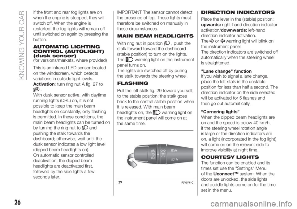
Pull the left stalk fig. 29 toward yourself,
to the stable position; the stalk goes
back to the central stable position when
it is released. With main beam
headlights on, the
warning light on
the instrument panel will come on at
the same time.DIRECTION INDICATORS
Place the lever in the (stable) position:
upwards:right-hand direction indicator
activation/downwards:left-hand
direction indicator activation.
The
orwarning light will blink on
the instrument panel.
The direction indicators are switched off
automatically when the steering wheel
is straightened.
"Lane change" function
If you wish to signal a lane change,
place the left stalk in the unstable
position for less than half a second. The
direction indicator on the side selected
will be activated for 5 flashes and
then go out automatically.
“Cornering lights”
When the dipped beam headlights are
on and the speed is below 40 km/h,
if the steering wheel rotation angle
is large or the direction indicators are
on, a light (incorporated in the fog light)
will come on on the relevant side to
improve visibility at night time.
COURTESY LIGHTS
The function can be enabled and its
times set use the "Settings" Menu
of theUconnect™system. When the
doors are unlocked, the side lights
and puddle lights come on for the time
set in the menu.
26
KNOWING YOUR CAR
")99;U;ZZY’
Page 46 of 248
DISPLAY
DESCRIPTION
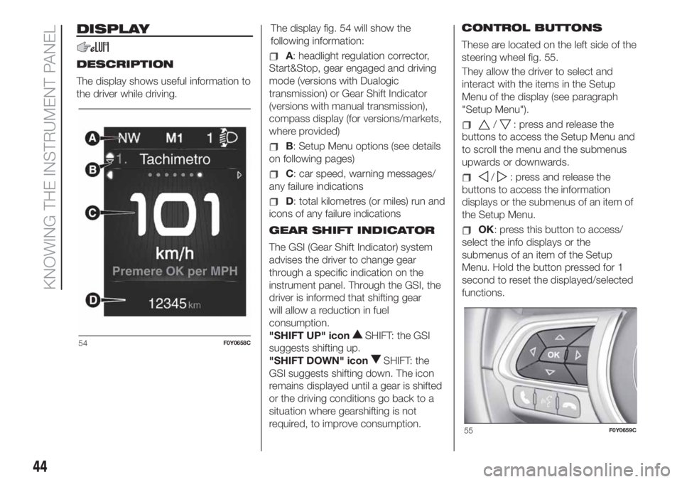
The display shows useful information to
the driver while driving.The display fig. 54 will show the
following information:A: headlight regulation corrector,
Start&Stop, gear engaged and driving
mode (versions with Dualogic
transmission) or Gear Shift Indicator
(versions with manual transmission),
compass display (for versions/markets,
where provided)
B: Setup Menu options (see details
on following pages)
C: car speed, warning messages/
any failure indications
D: total kilometres (or miles) run and
icons of any failure indications
GEAR SHIFT INDICATOR
The GSI (Gear Shift Indicator) system
advises the driver to change gear
through a specific indication on the
instrument panel. Through the GSI, the
driver is informed that shifting gear
will allow a reduction in fuel
consumption.
"SHIFT UP" icon
SHIFT: the GSI
suggests shifting up.
"SHIFT DOWN" icon
SHIFT: the
GSI suggests shifting down. The icon
remains displayed until a gear is shifted
or the driving conditions go back to a
situation where gearshifting is not
required, to improve consumption.CONTROL BUTTONS
These are located on the left side of the
steering wheel fig. 55.
They allow the driver to select and
interact with the items in the Setup
Menu of the display (see paragraph
"Setup Menu").
/: press and release the
buttons to access the Setup Menu and
to scroll the menu and the submenus
upwards or downwards.
/: press and release the
buttons to access the information
displays or the submenus of an item of
the Setup Menu.
OK: press this button to access/
select the info displays or the
submenus of an item of the Setup
Menu. Hold the button pressed for 1
second to reset the displayed/selected
functions.
54F0Y0658C
55F0Y0659C
44
KNOWING THE INSTRUMENT PANEL
Page 47 of 248
Speedometer
Trip
Vehicle info
Audio
Telephone (for versions/markets,
where provided)
Navigation (for versions/markets,
where provided)
Warnings
Vehicle Settings
When the ignition key is turned to the
MAR-ON position, the display shows
the last Menu option active before
the engine was switched off.
NOTE With theUconnect™system,
some Menu items are shown and
managed on the display of the latter
and not on the instrument panel display
(refer to the Multimedia chapter or to
the supplement available online).
Vehicle Settings
This menu item allows you to change
the settings for:
"Display"
"Safety / Assistance"
"Security"Display
By selecting item "Display" you can
access the settings/information
regarding: “Dimmer” (for versions/
markets, where provided), “Screen
Setup”, “See phone”, “See navigation”,
“Reset trip B automatic".
Safety / Assistance
By selecting “Safety / Assistance" you
can access the settings/information
regarding: “City Brake Control” (for
versions/markets, where provided),
“Parking sensor volume”, “Buzzer
volume”.
Safety
By selecting item "Security" you can
access the settings/information
regarding: “Hill Holder” (for versions/
markets, where provided), “Passenger
AIRBAG” (for versions/markets, where
provided), “Seat belt buzzer”, “Speed
beep”.
IMPORTANT Failure to top up the
engine oil could result in a low level,
which could prevent normal car
operation and even cause it to stop.
TRIP COMPUTER
The Trip computer is used to display
information on car operation when the
ignition key is turned to MAR.The Trip computer comprises:
Instantaneous info: displays the
“Range” and “Instantaneous
consumption" parameters.
"Trip A" displays the following
values: “Distance travelled”, “Travel
time”, “Average fuel consumption” and
“Average speed”
"Trip B" displays the following
values: “Distance travelled”, “Journey
time”, “Average fuel consumption” and
“Average speed”.
“Trip A” and “Trip B” monitor the car's
"complete missions" (trips) separately
from each other. The “Trip B” function
may be excluded.
The "Range" is also calculated and
displayed with the car at a standstill
and the engine running.
Reset “Trip A” / “Trip B”
Both functions can be reset (reset
means start of a new journey). To reset
the values, press and hold down the
OKbutton on the steering wheel (see
"Control buttons" section). The reset
only applies to the values displayed
(“Trip A” or “Trip: B”).
NOTE “Range” and “Instantaneous fuel
consumption" parameters cannot be
reset.
45
SETUP MENU
The Setup Menu includes the following
items:
Page 77 of 248
IMPORTANT After the car is stopped,
the brake callipers may be locked
for about 2 seconds for safety reasons.
Make sure you press the brake pedal
if the vehicle moves slightly forwards.
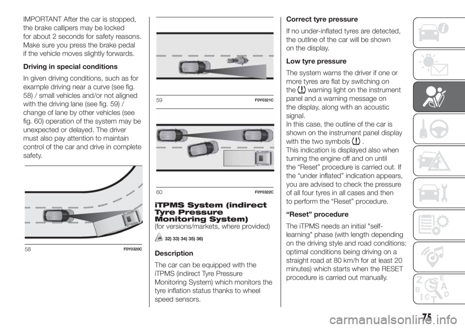
Driving in special conditions
In given driving conditions, such as for
example driving near a curve (see fig.
58) / small vehicles and/or not aligned
with the driving lane (see fig. 59) /
change of lane by other vehicles (see
fig. 60) operation of the system may be
unexpected or delayed. The driver
must also pay attention to maintain
control of the car and drive in complete
safety.
iTPMS System (indirect
Tyre Pressure
Monitoring System)
(for versions/markets, where provided)
32) 33) 34) 35) 36)
Description
The car can be equipped with the
iTPMS (indirect Tyre Pressure
Monitoring System) which monitors the
tyre inflation status thanks to wheel
speed sensors.Correct tyre pressure
If no under-inflated tyres are detected,
the outline of the car will be shown
on the display.
Low tyre pressure
The system warns the driver if one or
more tyres are flat by switching on
the
warning light on the instrument
panel and a warning message on
the display, along with an acoustic
signal.
In this case, the outline of the car is
shown on the instrument panel display
with the two symbols
.
This indication is displayed also when
turning the engine off and on until
the “Reset” procedure is carried out. If
the “under inflated” indication appears,
you are advised to check the pressure
of all four tyres in all cases and then
to perform the “Reset” procedure.
“Reset” procedure
The iTPMS needs an initial "self-
learning" phase (with length depending
on the driving style and road conditions:
optimal conditions being driving on a
straight road at 80 km/h for at least 20
minutes) which starts when the RESET
procedure is carried out manually.
58F0Y0320C
59F0Y0321C
60F0Y0322C
75
Page 78 of 248
The "Reset" procedure must be carried
out:
each time tyre pressure is modified;
when even only one tyre is changed;
when tyres are rotated/inverted;
when the space-saver wheel is
fitted.
Before carrying out the “Reset”
procedure, inflate the tyres to the rated
pressure values specified in the inflation
pressure table (see "Wheels" paragraph
in the "Technical specifications"
chapter).
If the “Reset” procedure is not carried
out, in all above cases, the
warning
light may give false indications on
one or more tyres.
To carry out the “Reset” procedure,
with the car stopped and the ignition
device at MAR, use the Setup Menu on
the display as follows:
go to "Vehicle info" and then to
"Reset tyres";
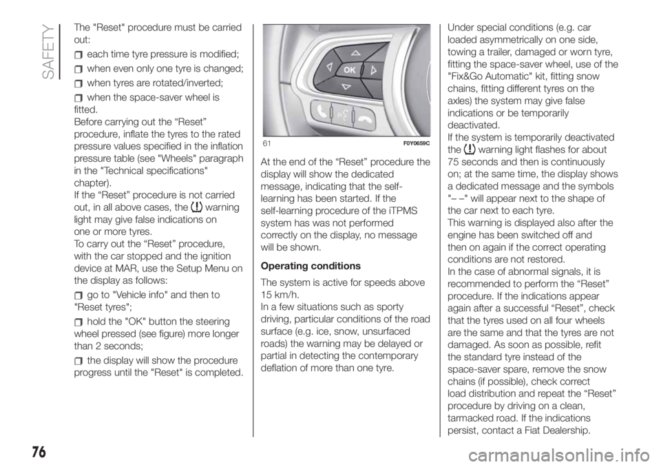
hold the "OK" button the steering
wheel pressed (see figure) more longer
than 2 seconds;
the display will show the procedure
progress until the "Reset" is completed.At the end of the “Reset” procedure the
display will show the dedicated
message, indicating that the self-
learning has been started. If the
self-learning procedure of the iTPMS
system has was not performed
correctly on the display, no message
will be shown.
Operating conditions
The system is active for speeds above
15 km/h.
In a few situations such as sporty
driving, particular conditions of the road
surface (e.g. ice, snow, unsurfaced
roads) the warning may be delayed or
partial in detecting the contemporary
deflation of more than one tyre.Under special conditions (e.g. car
loaded asymmetrically on one side,
towing a trailer, damaged or worn tyre,
fitting the space-saver wheel, use of the
"Fix&Go Automatic" kit, fitting snow
chains, fitting different tyres on the
axles) the system may give false
indications or be temporarily
deactivated.
If the system is temporarily deactivated
the
warning light flashes for about
75 seconds and then is continuously
on; at the same time, the display shows
a dedicated message and the symbols
"– –" will appear next to the shape of
the car next to each tyre.
This warning is displayed also after the
engine has been switched off and
then on again if the correct operating
conditions are not restored.
In the case of abnormal signals, it is
recommended to perform the “Reset”
procedure. If the indications appear
again after a successful “Reset”, check
that the tyres used on all four wheels
are the same and that the tyres are not
damaged. As soon as possible, refit
the standard tyre instead of the
space-saver spare, remove the snow
chains (if possible), check correct
load distribution and repeat the “Reset”
procedure by driving on a clean,
tarmacked road. If the indications
persist, contact a Fiat Dealership.61F0Y0659C
76
SAFETY
Page 125 of 248
HAZARD WARNING
LIGHTS
CONTROL
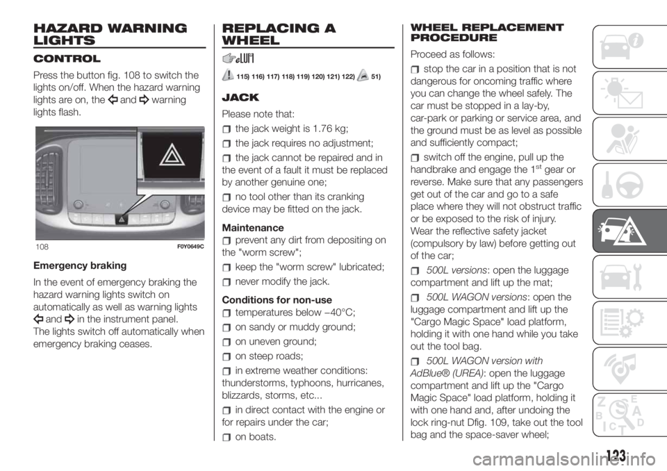
Press the button fig. 108 to switch the
lights on/off. When the hazard warning
lights are on, the
andwarning
lights flash.
Emergency braking
In the event of emergency braking the
hazard warning lights switch on
automatically as well as warning lights
andin the instrument panel.
The lights switch off automatically when
emergency braking ceases.
REPLACING A
WHEEL
115) 116) 117) 118) 119) 120) 121) 122)51)
JACK
Please note that:
the jack weight is 1.76 kg;
the jack requires no adjustment;
the jack cannot be repaired and in
the event of a fault it must be replaced
by another genuine one;
no tool other than its cranking
device may be fitted on the jack.
Maintenance
prevent any dirt from depositing on
the "worm screw";
keep the "worm screw" lubricated;
never modify the jack.
Conditions for non-use
temperatures below −40°C;
on sandy or muddy ground;
on uneven ground;
on steep roads;
in extreme weather conditions:
thunderstorms, typhoons, hurricanes,
blizzards, storms, etc...
in direct contact with the engine or
for repairs under the car;
on boats.WHEEL REPLACEMENT
PROCEDURE
Proceed as follows:
stop the car in a position that is not
dangerous for oncoming traffic where
you can change the wheel safely. The
car must be stopped in a lay-by,
car-park or parking or service area, and
the ground must be as level as possible
and sufficiently compact;
switch off the engine, pull up the
handbrake and engage the 1stgear or
reverse. Make sure that any passengers
get out of the car and go to a safe
place where they will not obstruct traffic
or be exposed to the risk of injury.
Wear the reflective safety jacket
(compulsory by law) before getting out
of the car;
500L versions: open the luggage
compartment and lift up the mat;
500L WAGON versions: open the
luggage compartment and lift up the
"Cargo Magic Space" load platform,
holding it with one hand while you take
out the tool bag.
500L WAGON version with
AdBlue® (UREA): open the luggage
compartment and lift up the "Cargo
Magic Space" load platform, holding it
with one hand and, after undoing the
lock ring-nut Dfig. 109, take out the tool
bag and the space-saver wheel;
108F0Y0649C
123
Page 128 of 248
7-seater versions
With third row of rear seats folded:
place the punctured tyre in the luggage
compartment, above the backrests.
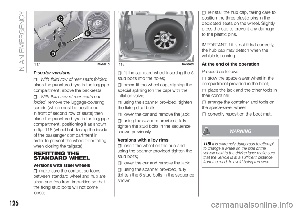
With third row of rear seats not
folded: remove the luggage-covering
curtain (which must be positioned
in front of second row of seats) then
place the punctured tyre in the luggage
compartment, positioning it as shown
in fig. 118 (wheel hub facing the inside
of the passenger compartment in
order to prevent the wheel from falling
when closing the tailgate).
REFITTING THE
STANDARD WHEEL
Versions with steel wheels
make sure the contact surfaces
between standard wheel and hub are
clean and free from impurities so that
the fixing stud bolts will not come
loose;
fit the standard wheel inserting the 5
stud bolts into the holes;
press-fit the wheel cap, aligning the
special splining (on the cap) with the
inflation valve;
using the spanner provided, tighten
the fixing stud bolts;
lower the car and remove the jack;
using the spanner provided, fully
tighten the stud bolts in the sequence
shown previously.
Versions with alloy rims
insert the wheel on the hub and
using the spanner provided tighten the
stud bolts;
lower the car and remove the jack;
using the spanner provided, fully
tighten the 5 stud bolts in the sequence
shown;
reinstall the hub cap, taking care to
position the three plastic pins in the
dedicated seats on the wheel. Slightly
press the cap to prevent any damage
to the plastic pins.
IMPORTANT If it is not fitted correctly,
the hub cap may detach when the
vehicle is running.
At the end of the operation
Proceed as follows:
stow the space-saver wheel in the
compartment provided in the boot;
place the jack and the other tools in
their container;
arrange the container and tools on
the space-saver wheel;
correctly reposition the boot mat.
WARNING
115)It is extremely dangerous to attempt
to change a wheel on the side of the
vehicle next to the driving lane: make sure
that the vehicle is at a sufficient distance
from the road, to avoid being run over.
117F0Y0361C118F0Y0368C
126
IN AN EMERGENCY
Page 129 of 248

116)The space-saver wheel (for
versions/markets where provided) is
specific to your car, do not use it on other
models, or use the space-saver wheel
of other models on your car. The
space-saver wheel must only be used in
the event of an emergency. Never use it for
more than strictly necessary and never
exceed 80 km/h. "Warning! For temporary
use only! 80km/h max! Replace with
standard wheel as soon as possible. Never
remove or cover the sticker on the
space-saver wheel. Never apply a wheel
cap on a space-saver wheel. The vehicle's
driving characteristics will be modified
with the space-saver wheel fitted. Avoid
violent acceleration and braking, abrupt
steering and fast cornering.
117)Alert other drivers that the car is
stationary in compliance with local
regulations: hazard warning lights, warning
triangle, etc. Any passengers on board
should leave the car, especially if it is
heavily laden. Passengers should stay
away from on-coming traffic while the
wheel is being changed. If you are on a
slope or uneven surface, place the wedge
provided under the wheel (see the
instructions on the next pages).118)The vehicle's driving characteristics
will be modified with the space-saver wheel
fitted. Avoid violent acceleration and
braking, abrupt steering and fast cornering.
The overall duration of the space-saver
wheel is of about 3000 km, after which the
relevant tyre must be replaced with another
one of the same type. Never install a
standard tyre on a rim that is designed for
use with a space-saver wheel. Have the
wheel repaired and refitted as soon as
possible. Using two or more space-saver
wheels at the same time is forbidden.
Do not grease the threads of the stud bolts
before fitting them: they might slip out.
119)The jack is a tool developed and
designed only for changing a wheel, if a
tyre gets punctured or damaged, on the
vehicle with which it is supplied or on other
vehicles of the same model. Any other
use, e.g. to jack up other vehicle models or
different things, is strictly prohibited. Never
use it to carry out maintenance or repairs
under the vehicle or to change summer/
winter wheels and vice versa: we advise
you to contact a Fiat Dealership. Never go
under the raised vehicle: use it only in
the positions indicated. Do not use the jack
for loads higher than the one shown on
its label. Never start the engine with vehicle
raised. If the vehicle is raised more than
necessary, everything can become more
unstable, with the risk of the vehicle
dropping violently. Thus, lift the car only as
needed in order to access the space-saver
spare wheel.120)The space-saver wheel cannot be
fitted with snow chains. If a front (drive) tyre
is punctured and chains are needed, use
a standard wheel from the rear axle and
install the space-saver wheel on the rear
axle. In this way, with two normal drive
wheels at the front axle, it is possible to use
snow chains.
121)When turning the jack handle make
sure that it can turn freely without scraping
your hand against the ground. The moving
components of the jack ("worm screw"
and joints) can also cause injuries: do not
touch them. If you come into contact
with lubricating grease, clean yourself
thoroughly.
122)Incorrectly fitting the wheel cap may
cause it to fall off when the car is in motion.
Never tamper with the inflation valve.
Never introduce tools of any kind between
rim and tyre. Check tyre and space-saver
wheel pressures regularly, complying
with the values given in the "Technical
specifications" chapter.
123)At the end of the operation of
raising/locking the space-saver wheel
device, the spanner must be extracted,
taking care NOT to turn it in the wrong
direction to facilitate the extraction of the
spanner itself, so as to prevent the
attachment device from being released and
the lack of safe restraint.
WARNING
51)Contact a Fiat Dealership as soon as
possible to have the correct tightening
of the wheel stud bolts checked.
127
Page 130 of 248
“Fix&Go Automatic”
KIT
124) 125)52)2)
DESCRIPTION
The Fix&Go Automatic kit is located in
the luggage compartment, inside a
dedicated container. The container is
also equipped with a screwdriver,
the tow hook and the funnel for
refuelling in an emergency. To access
the kit, open the luggage compartment
door, remove the load platform and
lift the covering carpet.
REPAIR PROCEDURE
Proceed as follows:
stop the car in a position that is not
dangerous for oncoming traffic where
you can change the wheel safely. The
car must be stopped in a lay-by,
car-park or parking or service area, and
the ground must be as level as possible
and sufficiently compact;
switch off the engine, pull up the
handbrake and engage the 1stgear or
reverse. Make sure that any passengers
get out of the car and go to a safe
place where they will not obstruct traffic
or be exposed to the risk of injury.
Wear the reflective safety jacket
(compulsory by law) before getting out
of the car;
Insert the cartridge A fig. 119
containing the sealant in the proper
compartment of the compressor B,
pressing it down hard. Remove the
adhesive speed label C and apply it in a
visible position;
wear the gloves;
remove the cap from the tyre valve
and connect and screw the transparent
tube of the sealing fluid D fig. 119
onto the valve. If a 250 ml cartridge is
present the housing of the transparent
tube is provided with removable ring
to facilitate extraction. Make sure that
the ON-OFF button F fig. 121 is in
the off position (button not pressed);
insert the electrical connector E fig.
120 in the 12 V current socket of the
car and start the engine;
operate the compressor by pressing
the ON-OFF button F fig. 121. When
the pressure shown in the "Wheels"
paragraph in the “Technical data”
chapter or on the specific label appears
on the pressure gauge G, stop the
compressor by pressing the ON-OFF
button again;
119F0Y0624C
120F0Y0625C
128
IN AN EMERGENCY