steering wheel FIAT 500X 2016 2.G Owner's Manual
[x] Cancel search | Manufacturer: FIAT, Model Year: 2016, Model line: 500X, Model: FIAT 500X 2016 2.GPages: 587, PDF Size: 5.18 MB
Page 227 of 587
WARNING!
•Being too close to the steering wheel or instrument
panel during Advanced Front Air Bag deployment
could cause serious injury, including death. Air
bags need room to inflate. Sit back, comfortably
extending your arms to reach the steering wheel or
instrument panel.
• Never place a rear-facing child restraint in front of
an air bag. A deploying Passenger Advanced Front
Air Bag can cause death or serious injury to a child
12 years or younger, including a child in a rear-
facing child restraint.
• Only use a rear-facing child restraint in a vehicle
with a rear seat.
Advanced Front Air Bag Features
The Advanced Front Air Bag system has multistage
driver and front passenger air bags. This system provides
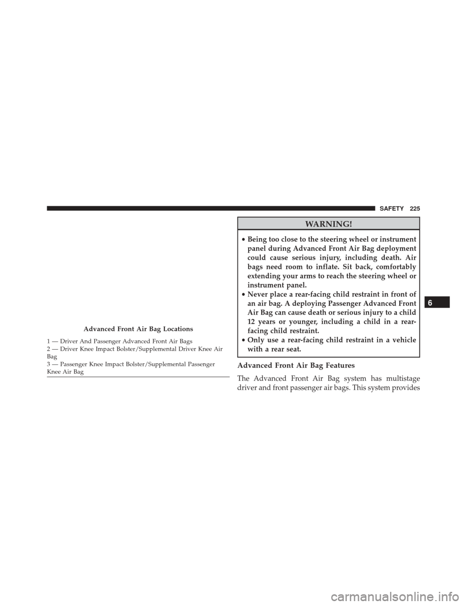
Advanced Front Air Bag Locations
1 — Driver And Passenger Advanced Front Air Bags
2 — Driver Knee Impact Bolster/Supplemental Driver Knee Air
Bag
3 — Passenger Knee Impact Bolster/Supplemental Passenger
Knee Air Bag
6
SAFETY 225
Page 228 of 587
output appropriate to the severity and type of collision as
determined by the Occupant Restraint Controller (ORC),
which may receive information from the front impact
sensors or other system components.
The first stage inflator is triggered immediately during an
impact that requires air bag deployment. A low energy
output is used in less severe collisions. A higher energy
output is used for more severe collisions.
This vehicle may be equipped with driver and/or front
passenger seat track position sensors that may adjust the
inflation rate of the Advanced Front Air Bags based upon
seat position.
This vehicle may be equipped with a driver and/or front
passenger seat belt buckle switch that detects whether
the driver or front passenger seat belt is buckled. The seat
belt buckle switch may adjust the inflation rate of the
Advanced Front Air Bags.WARNING!
•No objects should be placed over or near the air
bag on the instrument panel or steering wheel,
because any such objects could cause harm if the
vehicle is in a collision severe enough to cause the
air bags to inflate.
• Do not put anything on or around the air bag
covers or attempt to open them manually. You may
damage the air bags and you could be injured
because the air bags may no longer be functional.
The protective covers for the air bag cushions are
designed to open only when the air bags are
inflating.
• Relying on the air bags alone could lead to more
severe injuries in a collision. The air bags work
with your seat belt to restrain you properly. In
(Continued)
226 SAFETY
Page 229 of 587
WARNING!(Continued)
some collisions, air bags won’t deploy at all. Al-
ways wear your seat belts even though you have air
bags.
Advanced Front Air Bag Operation
Advanced Front Air Bags are designed to provide addi-
tional protection by supplementing the seat belts. Ad-
vanced Front Air Bags are not expected to reduce the risk
of injury in rear, side, or rollover collisions. The Ad-
vanced Front Air Bags will not deploy in all frontal
collisions, including some that may produce substantial
vehicle damage — for example, some pole collisions,
truck underrides, and angle offset collisions.
On the other hand, depending on the type and location of
impact, Advanced Front Air Bags may deploy in crashes
with little vehicle front-end damage but that produce a
severe initial deceleration. Because air bag sensors measure vehicle deceleration
over time, vehicle speed and damage by themselves are
not good indicators of whether or not an air bag should
have deployed.
Seat belts are necessary for your protection in all colli-
sions, and also are needed to help keep you in position,
away from an inflating air bag.
When the ORC detects a collision requiring the Ad-
vanced Front Air Bags, it signals the inflator units. A large
quantity of non-toxic gas is generated to inflate the
Advanced Front Air Bags.
The steering wheel hub trim cover and the upper right
side of the instrument panel separate and fold out of the
way as the air bags inflate to their full size. The Advanced
Front Air Bags fully inflate in less time than it takes to
blink your eyes. The air bags then quickly deflate while
helping to restrain the driver and front passenger.
6
SAFETY 227
Page 241 of 587
Redundant Air Bag Warning Light
If a fault with the Air Bag Warning Light is detected,which could affect the Supplemental Restraint
System (“SRS”), the Redundant Air Bag Warn-
ing Light will illuminate on the instrument
panel. The Redundant Air Bag Warning Light
will stay on until the fault is cleared. In addition, a single
chime will sound to alert you that the Redundant Air Bag
Warning Light has come on and a fault has been detected.
If the Redundant Air Bag Warning Light comes on
intermittently or remains on while driving have an
authorized dealer service the vehicle immediately. For
additional information regarding the Redundant Air Bag
Warning Light refer to the “Instrument Panel” section of
this manual.
Maintaining Your Air Bag System
WARNING!
• Modifications to any part of the air bag system
could cause it to fail when you need it. You could
be injured if the air bag system is not there to
protect you. Do not modify the components or
wiring, including adding any kind of badges or
stickers to the steering wheel hub trim cover or the
upper right side of the instrument panel. Do not
modify the front bumper, vehicle body structure, or
add aftermarket side steps or running boards.
• It is dangerous to try to repair any part of the air
bag system yourself. Be sure to tell anyone who
works on your vehicle that it has an air bag system.
• Do not attempt to modify any part of your air bag
system. The air bag may inflate accidentally or may
(Continued)
6
SAFETY 239
Page 303 of 587
position. Also, the transmission is locked in PARK when-
ever the ignition is in the STOP/OFF position.
Vehicles With Mechanical Key:
This vehicle is equipped with a Key Ignition Park Inter-
lock which requires the transmission to be in PARK
before the ignition can be turned to the STOP/OFF (key
removal) position. The key can only be removed from the
ignition when the ignition is in the STOP/OFF position,
and the transmission is locked in PARK whenever the
ignition is in the STOP/OFF position.
If the vehicle’s battery becomes discharged, the key will
be trapped in the ignition switch even when the shift
lever is in PARK. To extract the key, refer to “Ignition Key
Removal Override” in “In Case Of Emergency”.
Brake/Transmission Shift Interlock System
This vehicle is equipped with a Brake Transmission Shift
Interlock system (BTSI) that holds the shift lever in PARKunless the brakes are applied. To shift the transmission
out of PARK, the ignition switch must be turned to the
MAR/RUN position (engine running or not) and the
brake pedal must be pressed.
The brake pedal must also be pressed before pushing the
button on the shift lever to shift from NEUTRAL into
DRIVE or REVERSE when the vehicle is stopped or
moving at low speeds.
SPEED CONTROL — IF EQUIPPED
When engaged, the Speed Control takes over accelerator
operations at speeds greater than 25 mph (40 km/h).
The Speed Control buttons are located on the right side of
the steering wheel.7
STARTING AND OPERATING 301
Page 324 of 587
LaneSense system uses a forward looking camera to
detect lane markings and measure vehicle position
within the lane boundaries.
When both lane markings are detected and the driver
unintentionally drifts out of the lane (no turn signal
applied), the LaneSense system provides a haptic warn-
ing in the form of torque applied to the steering wheel to
prompt the driver to remain within the lane boundaries.
If the driver continues to unintentionally drift out of the
lane, the LaneSense system provides a visual warning
through the Electronic Vehicle Information Center (EVIC)
to prompt the driver to remain within the lane boundar-
ies.
The driver may manually override the haptic warning by
applying torque into the steering wheel at any time.
When only a single lane marking is detected and the
driver unintentionally drifts across the lane marking (no
turn signal applied), the LaneSense system provides avisual warning through the EVIC to prompt the driver to
remain within the lane. When only a single lane marking
is detected, a haptic (torque) warning will not be pro-
vided.
NOTE:
When operating conditions have been met, the
LaneSense system will monitor if the driver ’s hands are
on the steering wheel and provides an audible warning
to the driver when the driver ’s hands are not detected on
the steering wheel. The system will cancel if the driver
does not return their hands to the wheel.
Turning LaneSense ON Or OFF
The default status of LaneSense is “OFF”.
The LaneSense button is located on the end of the turn
signal stalk located on the steering column.
To turn the LaneSense system ON, push the
Lane Assist button (LED turns OFF). A “Lane
Sense On” message is shown in the EVIC.
322 STARTING AND OPERATING
Page 326 of 587
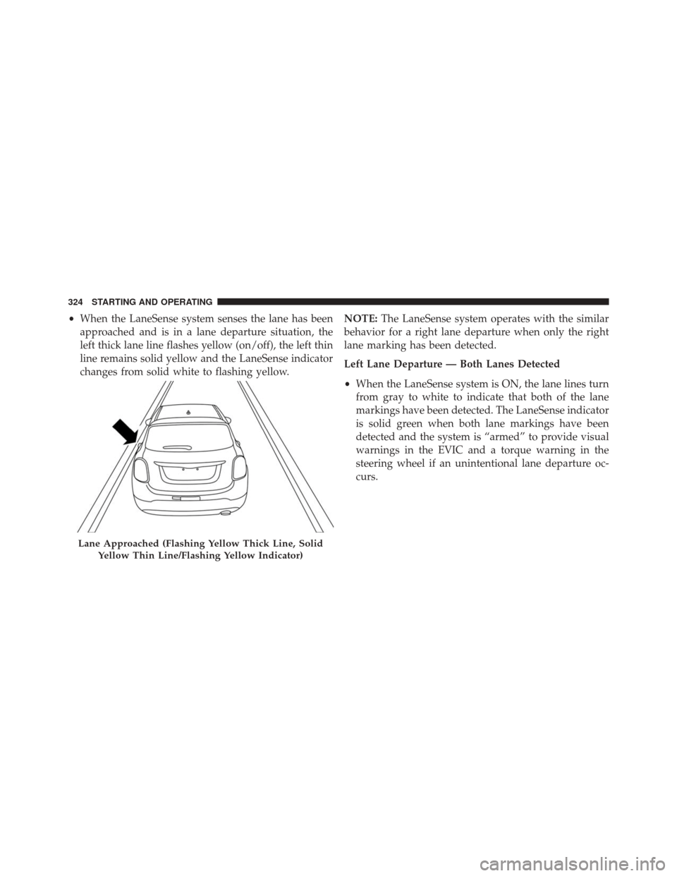
•When the LaneSense system senses the lane has been
approached and is in a lane departure situation, the
left thick lane line flashes yellow (on/off), the left thin
line remains solid yellow and the LaneSense indicator
changes from solid white to flashing yellow. NOTE:
The LaneSense system operates with the similar
behavior for a right lane departure when only the right
lane marking has been detected.
Left Lane Departure — Both Lanes Detected
• When the LaneSense system is ON, the lane lines turn
from gray to white to indicate that both of the lane
markings have been detected. The LaneSense indicator
is solid green when both lane markings have been
detected and the system is “armed” to provide visual
warnings in the EVIC and a torque warning in the
steering wheel if an unintentional lane departure oc-
curs.
Lane Approached (Flashing Yellow Thick Line, Solid
Yellow Thin Line/Flashing Yellow Indicator)
324 STARTING AND OPERATING
Page 327 of 587
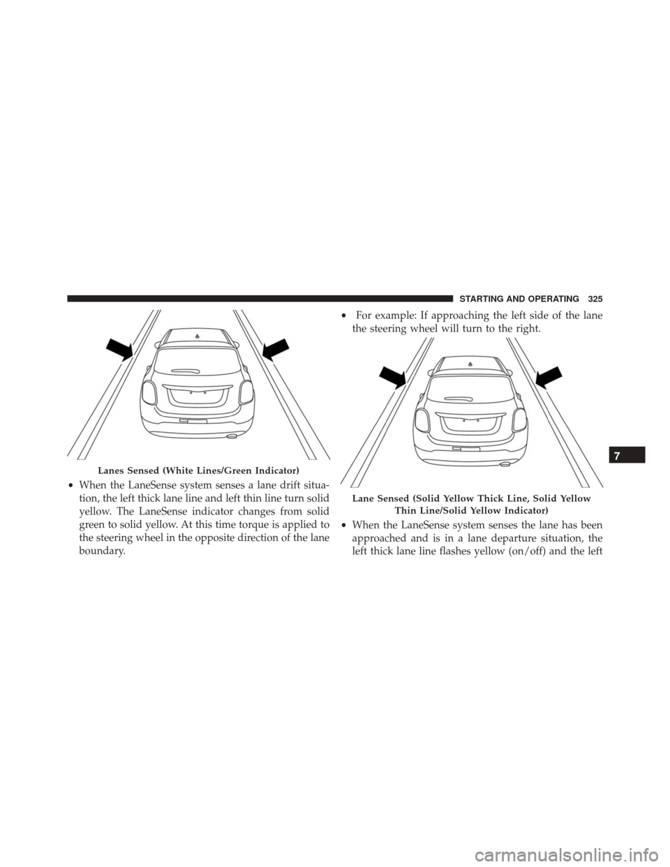
•When the LaneSense system senses a lane drift situa-
tion, the left thick lane line and left thin line turn solid
yellow. The LaneSense indicator changes from solid
green to solid yellow. At this time torque is applied to
the steering wheel in the opposite direction of the lane
boundary. •
For example: If approaching the left side of the lane
the steering wheel will turn to the right.
• When the LaneSense system senses the lane has been
approached and is in a lane departure situation, the
left thick lane line flashes yellow (on/off) and the left
Lanes Sensed (White Lines/Green Indicator)
Lane Sensed (Solid Yellow Thick Line, Solid Yellow
Thin Line/Solid Yellow Indicator)
7
STARTING AND OPERATING 325
Page 328 of 587
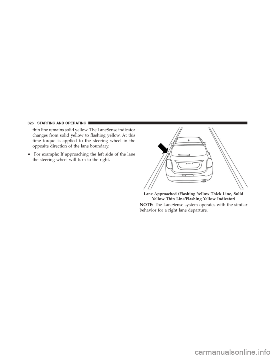
thin line remains solid yellow. The LaneSense indicator
changes from solid yellow to flashing yellow. At this
time torque is applied to the steering wheel in the
opposite direction of the lane boundary.
• For example: If approaching the left side of the lane
the steering wheel will turn to the right.
NOTE:The LaneSense system operates with the similar
behavior for a right lane departure.
Lane Approached (Flashing Yellow Thick Line, Solid
Yellow Thin Line/Flashing Yellow Indicator)
326 STARTING AND OPERATING
Page 329 of 587
Changing LaneSense Status
The LaneSense system has settings to adjust the intensity
of the torque warning and the warning zone sensitivity
(early/late) that you can configure through the Uconnect
system screen. Refer to “Uconnect Settings” in “Multime-
dia” for further information.
NOTE:
•When enabled the system operates above 37 mph
(60 km/h) and below 112 mph (180 km/h).
• Use of the turn signal suppresses the warnings.
• The system will not apply torque to the steering wheel
whenever a safety system engages. (anti-lock brakes,
traction control system, electronic stability control,
forward collision warning, etc.).
PARKVIEW REAR BACK UP CAMERA — IF
EQUIPPED
The ParkView Rear Back Up Camera that allows you to
see an on-screen image of your vehicle’s rear surround-
ings when the shift lever is put into REVERSE. The image
will be displayed on the touchscreen display along with
a note to “check entire surroundings” across the top of
the screen. After five seconds this note will disappear.
The ParkView camera is located above the rear license
plate.
7
STARTING AND OPERATING 327