boot FIAT 500X 2017 Owner handbook (in English)
[x] Cancel search | Manufacturer: FIAT, Model Year: 2017, Model line: 500X, Model: FIAT 500X 2017Pages: 284, PDF Size: 11.14 MB
Page 11 of 284
GETTING TO KNOW YOUR CAR
In-depth knowledge of your new vehicle
starts here.
The booklet that you are reading simply
and directly explains how it is made and
how it works.
That’s why we advise you to read it
seated comfortably on board, so that
you can see immediately what is
described here for yourself.DASHBOARD...............10
THE KEYS.................11
IGNITION DEVICE............12
FIAT CODE.................14
ALARM...................14
DOORS...................15
SEATS....................18
HEAD RESTRAINTS...........21
STEERING WHEEL............22
REAR VIEW MIRRORS.........23
EXTERIOR LIGHTS............24
INTERIOR LIGHTS............28
WINDSCREEN/REAR WINDOW
WIPER...................29
CLIMATE CONTROL SYSTEM.....33
ELECTRIC WINDOWS..........37
ELECTRIC SUN ROOF.........38
BONNET..................40
BOOT....................41
9
Page 13 of 284
THE KEYS
KEY WITH REMOTE
CONTROL
1)
1)
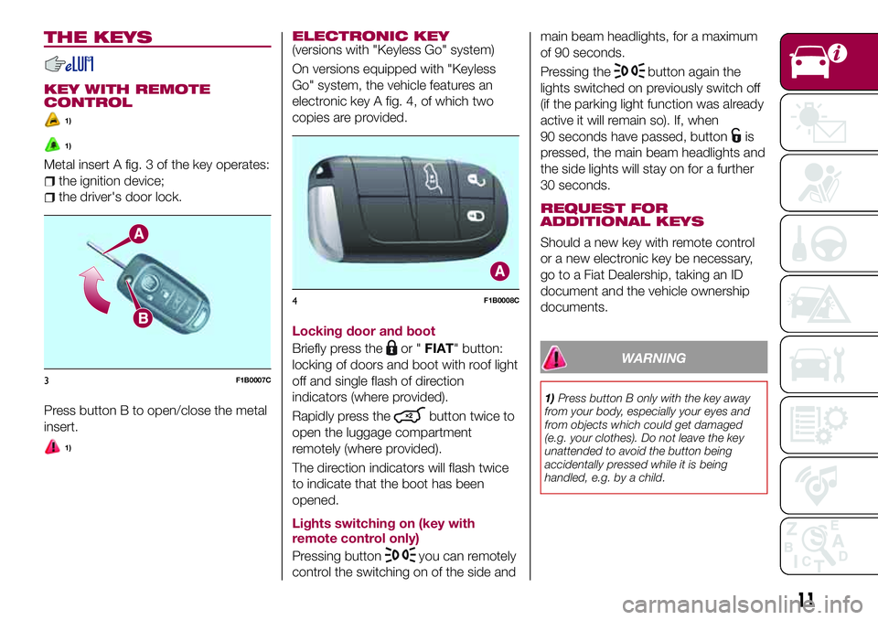
Metal insert A fig. 3 of the key operates:
the ignition device;
the driver's door lock.
Press button B to open/close the metal
insert.
1)
ELECTRONIC KEY(versions with "Keyless Go" system)
On versions equipped with "Keyless
Go" system, the vehicle features an
electronic key A fig. 4, of which two
copies are provided.
Locking door and boot
Briefly press the
or "FIAT" button:
locking of doors and boot with roof light
off and single flash of direction
indicators (where provided).
Rapidly press the
button twice to
open the luggage compartment
remotely (where provided).
The direction indicators will flash twice
to indicate that the boot has been
opened.
Lights switching on (key with
remote control only)
Pressing button
you can remotely
control the switching on of the side andmain beam headlights, for a maximum
of 90 seconds.
Pressing the
button again the
lights switched on previously switch off
(if the parking light function was already
active it will remain so). If, when
90 seconds have passed, button
is
pressed, the main beam headlights and
the side lights will stay on for a further
30 seconds.
REQUEST FOR
ADDITIONAL KEYS
Should a new key with remote control
or a new electronic key be necessary,
go to a Fiat Dealership, taking an ID
document and the vehicle ownership
documents.
WARNING
1)Press button B only with the key away
from your body, especially your eyes and
from objects which could get damaged
(e.g. your clothes). Do not leave the key
unattended to avoid the button being
accidentally pressed while it is being
handled, e.g. by a child.
3F1B0007C
4F1B0008C
11
Page 14 of 284
IMPORTANT
1)The electronic components inside the
key may be damaged if the key is subjected
to strong shocks. In order to ensure
complete efficiency of the electronic
devices inside the key, it should never be
exposed to direct sunlight.
IMPORTANT
1)Used batteries may be harmful to the
environment if not disposed of correctly.
They must be disposed of as specified by
law in the special containers or taken to a
Fiat Dealership, which will take care of their
disposal.
IGNITION DEVICE
Versions with key without remote
control
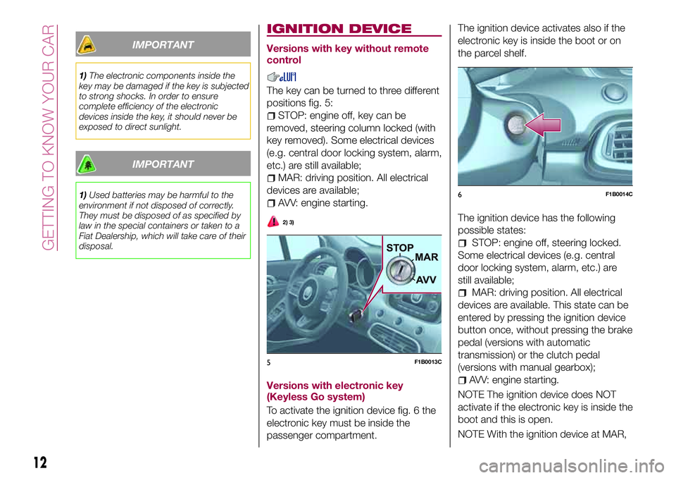
The key can be turned to three different
positions fig. 5:
STOP: engine off, key can be
removed, steering column locked (with
key removed). Some electrical devices
(e.g. central door locking system, alarm,
etc.) are still available;
MAR: driving position. All electrical
devices are available;
AVV: engine starting.
2) 3)
Versions with electronic key
(Keyless Go system)
To activate the ignition device fig. 6 the
electronic key must be inside the
passenger compartment.The ignition device activates also if the
electronic key is inside the boot or on
the parcel shelf.
The ignition device has the following
possible states:
STOP: engine off, steering locked.
Some electrical devices (e.g. central
door locking system, alarm, etc.) are
still available;
MAR: driving position. All electrical
devices are available. This state can be
entered by pressing the ignition device
button once, without pressing the brake
pedal (versions with automatic
transmission) or the clutch pedal
(versions with manual gearbox);
AVV: engine starting.
NOTE The ignition device does NOT
activate if the electronic key is inside the
boot and this is open.
NOTE With the ignition device at MAR,
5F1B0013C
6F1B0014C
12
GETTING TO KNOW YOUR CAR
Page 19 of 284
Driver side door emergency
opening
If the electronic key does not work (e.g.
because its battery is flat or the vehicle
battery is flat), the emergency metal
insert inside the key can in any case be
used to operate the lock, unlocking the
driver's door.
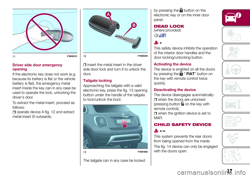
To extract the metal insert, proceed as
follows:
operate device A fig. 12 and extract
metal insert B outwards;
insert the metal insert in the driver
side door lock and turn it to unlock the
door.
Tailgate locking
Approaching the tailgate with a valid
electronic key, press the fig. 13 opening
button under the handle of the tailgate
to lock/unlock the boot.
The tailgate can in any case be lockedby pressing the
button on the
electronic key or on the inner door
panel.
DEAD LOCK(where provided)
8)
This safety device inhibits the operation
of the interior door handles and the
door locking/unlocking button.
Activating the device
The device is enabled on all the doors
by pressing the
"FIAT" button on
the key with remote control twice
quickly.
Deactivating the device
The device disengages automatically:
when the doors are unlocked
(pressing button
on the key with
remote control);
when the ignition device is set to
MAR.
CHILD SAFETY DEVICE
9) 10)
This system prevents the rear doors
from being opened from the inside.
The fig. 14 device can only be engaged
with the doors open:
11F1B0251C12F1B0020C
13F1B0166C
17
Page 22 of 284
You can select two heating levels:
"minimum heating": (one orange
LED lit on the buttons);
"maximum heating": two orange
LEDs lit on the buttons.
After selecting one heating level, you
need to wait for a few minutes until
warm air flows into the compartment.
When the "maximum heating" setting is
selected, the heater produces a
boosted heat level for the first minutes
of operation.
IMPORTANT To preserve the battery
charge, this function cannot be
activated when the engine is off.
REAR SEATS
Partial extension of the boot (1/3 or
2/3)
13)
6)
remove the rear shelf;
completely lower the rear seat head
restraints;
move the seat belt to the side,
making sure that it is fully extended and
not twisted;
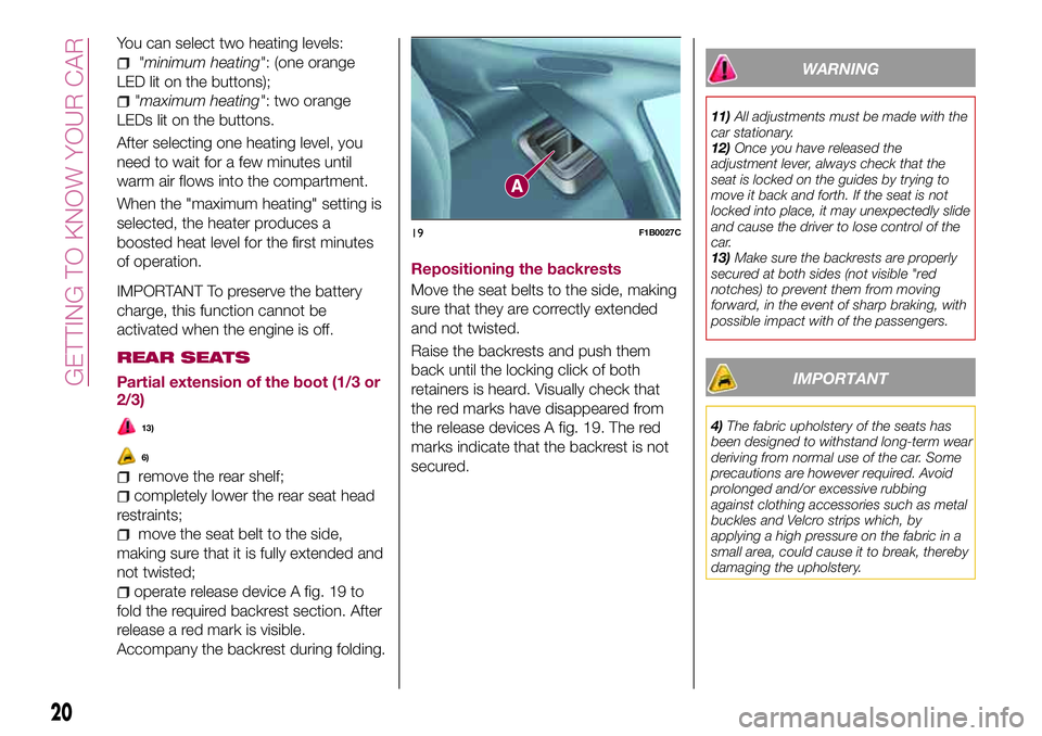
operate release device A fig. 19 to
fold the required backrest section. After
release a red mark is visible.
Accompany the backrest during folding.Repositioning the backrests
Move the seat belts to the side, making
sure that they are correctly extended
and not twisted.
Raise the backrests and push them
back until the locking click of both
retainers is heard. Visually check that
the red marks have disappeared from
the release devices A fig. 19. The red
marks indicate that the backrest is not
secured.
WARNING
11)All adjustments must be made with the
car stationary.
12)Once you have released the
adjustment lever, always check that the
seat is locked on the guides by trying to
move it back and forth. If the seat is not
locked into place, it may unexpectedly slide
and cause the driver to lose control of the
car.
13)Make sure the backrests are properly
secured at both sides (not visible "red
notches) to prevent them from moving
forward, in the event of sharp braking, with
possible impact with of the passengers.
IMPORTANT
4)The fabric upholstery of the seats has
been designed to withstand long-term wear
deriving from normal use of the car. Some
precautions are however required. Avoid
prolonged and/or excessive rubbing
against clothing accessories such as metal
buckles and Velcro strips which, by
applying a high pressure on the fabric in a
small area, could cause it to break, thereby
damaging the upholstery.
19F1B0027C
20
GETTING TO KNOW YOUR CAR
Page 29 of 284
central position and pushed again
towards the dashboard in the stable
position, this is interpreted as a request
for fixed main beam headlights: the
warning light comes on in the
instrument panel and the main beam
headlights turn on until vehicle speed
exceeds 40 km/h again. When this
threshold is exceeded the function
activates again automatically and the
warning light comes on again in
the instrument panel.
To deactivate this function, rotate the
light switch ring nut to the
position.
DIRECTION INDICATORS
Bring left stalk A fig. 30 to the (stable)
position:
upwards: activates the right direction
indicator;
downwards: activates the left direction
indicator.
The
orwarning light respectively
will flash on the instrument panel.
The direction indicators switch off
automatically when the steering wheel
is straightened or when the daytime
running lights (DRL)/parking lights are
activated."Lane Change" function
If you wish to signal a lane change while
running, place the left stalk in the
unstable position for less than half a
second.
The direction indicator on the side
selected will flash five times and then
switch off automatically.
HEADLIGHT ALIGNMENT
ADJUSTMENT
Headlight alignment corrector
The headlight alignment corrector
operates with ignition device at MAR
and dipped headlights on.
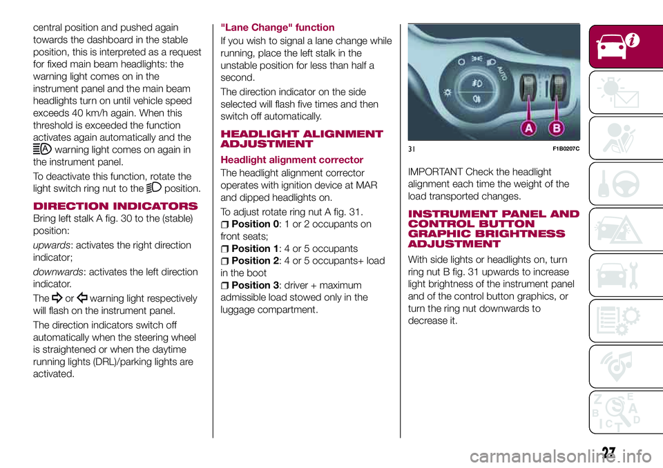
To adjust rotate ring nut A fig. 31.
Position 0: 1 or 2 occupants on
front seats;
Position 1: 4 or 5 occupants
Position 2: 4 or 5 occupants+ load
in the boot
Position 3: driver + maximum
admissible load stowed only in the
luggage compartment.
IMPORTANT Check the headlight
alignment each time the weight of the
load transported changes.
INSTRUMENT PANEL AND
CONTROL BUTTON
GRAPHIC BRIGHTNESS
ADJUSTMENT
With side lights or headlights on, turn
ring nut B fig. 31 upwards to increase
light brightness of the instrument panel
and of the control button graphics, or
turn the ring nut downwards to
decrease it.
31F1B0207C
27
Page 43 of 284
BOOT
The boot unlocking is electrically
operated and is deactivated when the
vehicle is in motion.
OPENING
27)
Opening from the outside
When unlocked, the tailgate can be
opened from outside the vehicle using
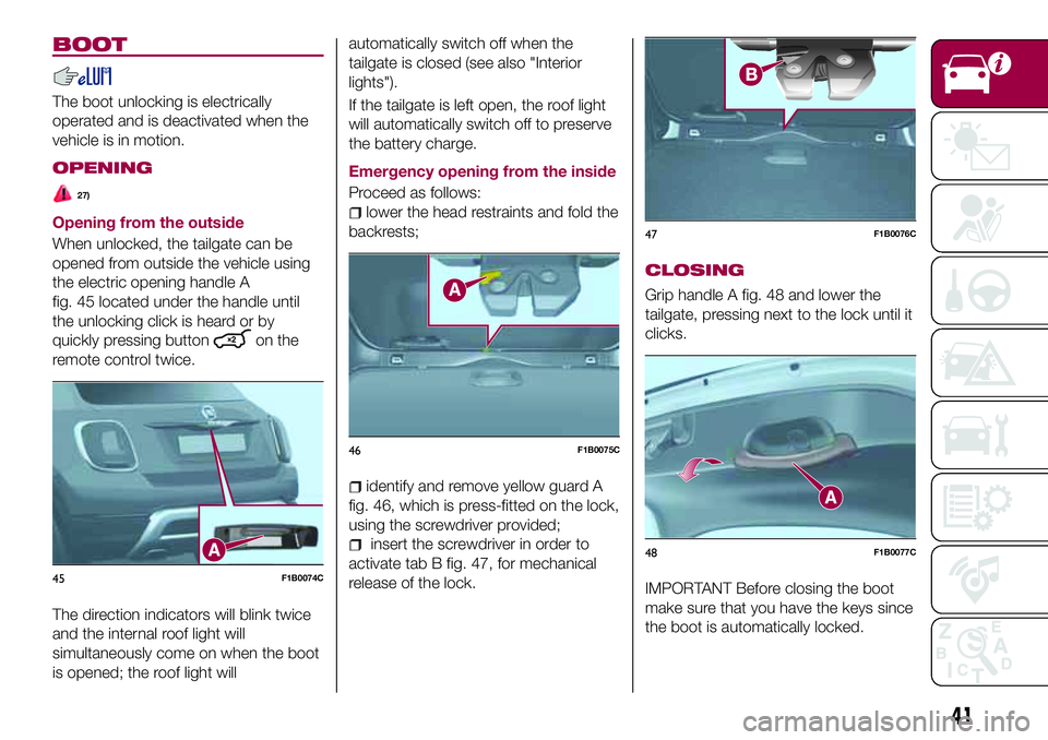
the electric opening handle A
fig. 45 located under the handle until
the unlocking click is heard or by
quickly pressing button
on the
remote control twice.
The direction indicators will blink twice
and the internal roof light will
simultaneously come on when the boot
is opened; the roof light willautomatically switch off when the
tailgate is closed (see also "Interior
lights").
If the tailgate is left open, the roof light
will automatically switch off to preserve
the battery charge.
Emergency opening from the inside
Proceed as follows:
lower the head restraints and fold the
backrests;
identify and remove yellow guard A
fig. 46, which is press-fitted on the lock,
using the screwdriver provided;
insert the screwdriver in order to
activate tab B fig. 47, for mechanical
release of the lock.
CLOSING
Grip handle A fig. 48 and lower the
tailgate, pressing next to the lock until it
clicks.
IMPORTANT Before closing the boot
make sure that you have the keys since
the boot is automatically locked.45F1B0074C
46F1B0075C
47F1B0076C
48F1B0077C
41
Page 44 of 284
BOOT INITIALISATION
IMPORTANT If the battery is
disconnected or the protection fuse
blows, the boot opening/closing
mechanism must be reinitialised as
follows:
close all the doors and the boot;
press the"FIAT" button on the
remote control;
press thebutton on the remote
control.
LOAD COMPARTMENT
Reconfigurable load platform
12)
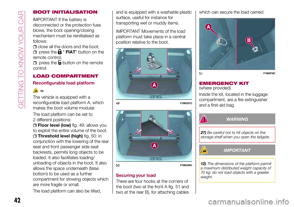
The vehicle is equipped with a
reconfigurable load platform A, which
makes the boot volume modular.
The load platform can be set to
2 different positions:
Floor level (low)fig. 49: allows you
to exploit the entire volume of the boot.
Threshold level (high)fig. 50: in
conjunction with the lowering of the rear
seat and front passenger side seat
backrests, permits long objects to be
loaded. It also facilitates loading/
unloading of objects in the boot. It also
allows the space underneath (false
bottom) to be used as a further
compartment for stowing objects which
are more fragile or small.
The load platform can also be tilted,and is equipped with a washable plastic
surface, useful for instance for
transporting wet or muddy items.
IMPORTANT Movements of the load
platform must take place in a central
position relative to the boot.
Securing your load
There are four hooks at the corners of
the boot (two at the front A fig. 51 and
two at the rear B), for attaching cableswhich can secure the load carried.
EMERGENCY KIT(where provided)
Inside the kit, located in the luggage
compartment, are a fire extinguisher
and a first-aid bag.
WARNING
27)Be careful not to hit objects on the
storage shelf when you open the tailgate.
IMPORTANT
12)The dimensions of the platform permit
a maximum distributed weight capacity of
70 kg: do not load objects with a greater
weight.
49F1B0327C
50F1B0328C
51F1B0079C
42
GETTING TO KNOW YOUR CAR
Page 142 of 284
REFUELLING THE
VEHICLE
133) 134) 135)
PETROL ENGINES
Only use unleaded petrol with a number
of octanes (R.O.N.) not lower than 95
(EN 228 specification).
DIESEL ENGINES
64)
Only use Diesel for motor vehicles (EN
590 specification).
When using or parking the vehicle for a
long time in the mountains or cold
areas, it is advisable to refuel using
locally available diesel. In this case, it is
also advisable to keep the tank over
50% full.
REFUELLING
PROCEDURE
"Capless Fuel" is a device at the
opening for the fuel tank which opens
and recloses automatically when the
fuel supply gun is introduced/removed.
The "Capless Fuel" device is provided
with an inhibitor which prevents
refuelling with incorrect fuel.
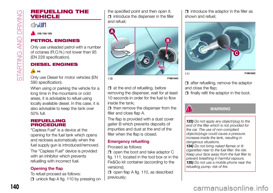
Opening the flap
To refuel proceed as follows:
unlock flap A fig. 110 by pressing onthe specified point and then open it;
introduce the dispenser in the filler
and refuel;
at the end of refuelling, before
removing the dispenser, wait for at least
10 seconds in order for the fuel to flow
inside the tank;
then remove the dispenser from the
filler and close flap A.
The flap is provided with a dust cover
gaiter B which prevents deposits of
impurities and dust at the end of the
filler when the flap is closed.
Emergency refuelling
Proceed as follows:
open the boot and take adaptor C
fig. 111, located in the tool box or in the
Fix&Go kit container (according to the
versions);
open flap A fig. 110, as described
previously;
introduce the adaptor in the filler as
shown and refuel;
after refuelling, remove the adaptor
and close the flap;
finally refit the adaptor in the boot.
WARNING
133)Do not apply any object/plug to the
end of the filler which is not provided for
the car. The use of non-compliant
objects/plugs could cause a pressure
increase inside the tank, resulting in
dangerous situations.
134)Do not bring naked flames or lit
cigarettes near to the fuel filler: fire risk.
Keep your face away from the fuel filler to
prevent breathing in harmful vapours.
135)Do not use a mobile phone near the
refuelling pump: risk of fire.
110F1B0164C111F1B0165C
140
STARTING AND DRIVING
Page 147 of 284
Light bulbs Type Power Figure reference
Front side lights/Daytime running lights (DRL) W21W 21W B
Rear side/brake light P21W 21W B
Main beam/dipped beam headlights (halogen) H4 60/55W D
Main beam/dipped beam headlights (Xenon gas discharge) D5S 25W F
Front direction indicators PY21W 21W B
Rear direction indicators P21W 21W B
Side direction indicators (on door mirror) WY5W 5W A
Third brake light LED – –
Number plate W5W 5W A
Fog lights H8 35W E
Rear fog light P21W 21W B
Reverse gear P21W 21W B
Front ceiling light C5W 5W A
Front ceiling lights (sun visors) C5W 5W A
Rear ceiling light (versions without sunroof) XENON 6W A
Rear ceiling lights (versions with sunroof) C5W 5W C
Boot ceiling lights W5W 5W A
Glove compartment light W5W 5W A
145