change wheel FIAT 500X 2017 Owner handbook (in English)
[x] Cancel search | Manufacturer: FIAT, Model Year: 2017, Model line: 500X, Model: FIAT 500X 2017Pages: 284, PDF Size: 11.14 MB
Page 12 of 284
DASHBOARD
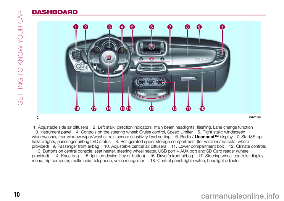
1. Adjustable side air diffusers 2. Left stalk: direction indicators, main beam headlights, flashing, Lane change function
3. Instrument panel 4. Controls on the steering wheel: Cruise control, Speed Limiter 5. Right stalk: windscreen
wiper/washer, rear window wiper/washer, rain sensor sensitivity level setting 6. Radio /Uconnect™display 7. Start&Stop,
hazard lights, passenger airbag LED status 8. Refrigerated upper storage compartment (for versions/markets, where
provided) 9. Passenger front airbag 10. Adjustable central air diffusers 11. Lower compartment box 12. Climate controls
13. Buttons on central console: seat heater, steering wheel heater, USB port + AUX port and SD Card reader (where
provided) 14. Knee bag 15. Ignition device (key or button) 16. Driver's front airbag 17. Steering wheel controls: display
menu, trip computer, multimedia, telephone, voice recognition 18. Control panel: light switch, headlight adjuster.
1211
2F1B0321C
10
GETTING TO KNOW YOUR CAR
Page 29 of 284
central position and pushed again
towards the dashboard in the stable
position, this is interpreted as a request
for fixed main beam headlights: the
warning light comes on in the
instrument panel and the main beam
headlights turn on until vehicle speed
exceeds 40 km/h again. When this
threshold is exceeded the function
activates again automatically and the
warning light comes on again in
the instrument panel.
To deactivate this function, rotate the
light switch ring nut to the
position.
DIRECTION INDICATORS
Bring left stalk A fig. 30 to the (stable)
position:
upwards: activates the right direction
indicator;
downwards: activates the left direction
indicator.
The
orwarning light respectively
will flash on the instrument panel.
The direction indicators switch off
automatically when the steering wheel
is straightened or when the daytime
running lights (DRL)/parking lights are
activated."Lane Change" function
If you wish to signal a lane change while
running, place the left stalk in the
unstable position for less than half a
second.
The direction indicator on the side
selected will flash five times and then
switch off automatically.
HEADLIGHT ALIGNMENT
ADJUSTMENT
Headlight alignment corrector
The headlight alignment corrector
operates with ignition device at MAR
and dipped headlights on.
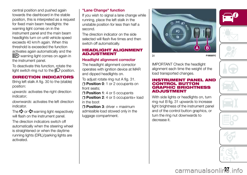
To adjust rotate ring nut A fig. 31.
Position 0: 1 or 2 occupants on
front seats;
Position 1: 4 or 5 occupants
Position 2: 4 or 5 occupants+ load
in the boot
Position 3: driver + maximum
admissible load stowed only in the
luggage compartment.
IMPORTANT Check the headlight
alignment each time the weight of the
load transported changes.
INSTRUMENT PANEL AND
CONTROL BUTTON
GRAPHIC BRIGHTNESS
ADJUSTMENT
With side lights or headlights on, turn
ring nut B fig. 31 upwards to increase
light brightness of the instrument panel
and of the control button graphics, or
turn the ring nut downwards to
decrease it.
31F1B0207C
27
Page 48 of 284
DISPLAY
DESCRIPTION
The vehicle is equipped with a display
that can show useful information to the
driver while driving.
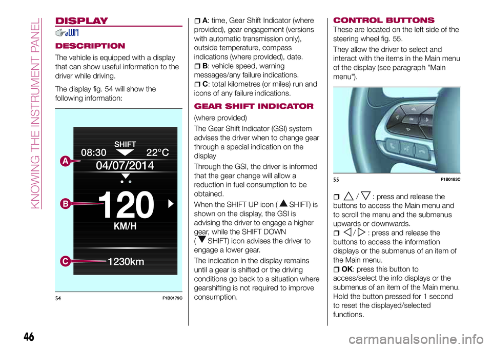
The display fig. 54 will show the
following information:
A: time, Gear Shift Indicator (where
provided), gear engagement (versions
with automatic transmission only),
outside temperature, compass
indications (where provided), date.
B: vehicle speed, warning
messages/any failure indications.
C: total kilometres (or miles) run and
icons of any failure indications.
GEAR SHIFT INDICATOR
(where provided)
The Gear Shift Indicator (GSI) system
advises the driver when to change gear
through a special indication on the
display
Through the GSI, the driver is informed
that the gear change will allow a
reduction in fuel consumption to be
obtained.
When the SHIFT UP icon (
SHIFT) is
shown on the display, the GSI is
advising the driver to engage a higher
gear, while the SHIFT DOWN
(
SHIFT) icon advises the driver to
engage a lower gear.
The indication in the display remains
until a gear is shifted or the driving
conditions go back to a situation where
gearshifting is not required to improve
consumption.
CONTROL BUTTONS
These are located on the left side of the
steering wheel fig. 55.
They allow the driver to select and
interact with the items in the Main menu
of the display (see paragraph "Main
menu").
/: press and release the
buttons to access the Main menu and
to scroll the menu and the submenus
upwards or downwards.
/: press and release the
buttons to access the information
displays or the submenus of an item of
the Main menu.
OK: press this button to
access/select the info displays or the
submenus of an item of the Main menu.
Hold the button pressed for 1 second
to reset the displayed/selected
functions.
08:30
KM/H
120
22°C
04/07/2014
1230km
54F1B0179C
55F1B0183C
46
KNOWING THE INSTRUMENT PANEL
Page 71 of 284
WARNING
28)If, when the ignition device is turned to MAR, thewarning light does not switch on or stays on whilst driving, a failure may have
occurred in the restraint systems. In this case the airbags or pretensioners may not be deployed in an impact or, in a lower number of cases,
they may be deployed accidentally. Before continuing, contact a Fiat Dealership immediately to have the system checked.
29)The fault of the
warning light is signalled by the switching on of theicon on the instrument panel. In this case, the warning light may
not indicate any faults with the restraint systems. Before continuing, contact a Fiat Dealership immediately to have the system checked.
30)If a failure is present with sharp braking, the rear wheels may lock and the vehicle may swerve.
IMPORTANT
13)If, turning the ignition device to MAR, thewarning light does not turn on or if it turns on steadily or flashing when travelling (on some
versions together with the message on the display), contact a Fiat Dealership as soon as possible.
14)If the warning light (or the icon on the display) flashes whilst driving, contact a Fiat Dealership.
15)If the symbol switches on when driving, stop the engine immediately and contact a Fiat Dealership.
16)Driving the vehicle with this symbol on may severely damage the gearbox, with resulting breakage. The oil may also overheat: contact with
hot engine or with exhaust components at high temperature could cause fires.
17)The presence of water in the fuel system circuit may cause severe damage to the injection system and irregular engine operation. If the
symbol is displayed contact a Fiat Dealership as soon as possible to bleed the system. If the above indications come on immediately after
refuelling, water has probably been poured into the tank: switch the engine off immediately and contact a Fiat Dealership.
18)Vehicle travel speed should always be adapted to the traffic and weather conditions, and must always comply with traffic regulations. The
engine can be stopped even if the DPF warning light is on: however, repeated interruptions of the regeneration process could cause
premature deterioration of the engine oil. For this reason it is always advisable to wait for the symbol to go off before turning off the engine,
following the instructions above. Do not complete the DPF regeneration process when the vehicle is stopped.
19)If the
warning light comes on, the exhausted engine oil should be changed as soon as possible, never drive more than 500 km from
the first switching-on of this warning light. Failure to observe the above may result in severe damage to the engine and invalidate the warranty.
Remember that when this warning light comes on, it does not mean that the level of engine oil is low, so if it flashes you do not need to top up
the engine oil.
20)If the symbol flashes when driving, contact a Fiat Dealership.
69
Page 83 of 284
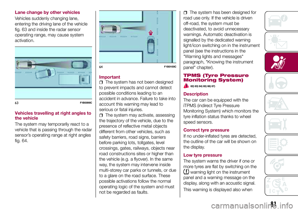
Lane change by other vehicles
Vehicles suddenly changing lane,
entering the driving lane of the vehicle
fig. 63 and inside the radar sensor
operating range, may cause system
activation.
Vehicles travelling at right angles to
the vehicle
The system may temporarily react to a
vehicle that is passing through the radar
sensor’s operating range at right angles
fig. 64.Important
The system has not been designed
to prevent impacts and cannot detect
possible conditions leading to an
accident in advance. Failure to take into
account this warning may lead to
serious or fatal injuries.
The system may activate, assessing
the trajectory of the vehicle, due to the
presence of reflective metal objects
different from other vehicles, such as
safety barriers, road signs, barriers
before parking lots, tollgates, level
crossings, gates, railways, objects near
road constructions sites or higher than
the vehicle (e.g. a flyover). In the same
way, the system may intervene inside
multi-storey car parks or tunnels, or due
to a glare on the road surface. These
possible activations follow the normal
operating logic of the system and must
not be regarded as faults.
The system has been designed for
road use only. If the vehicle is driven
off-road, the system must be
deactivated, to avoid unnecessary
warnings. Automatic deactivation is
signalled by the dedicated warning
light/icon switching on in the instrument
panel (see the instructions in the
"Warning lights and messages"
paragraph, "Knowing the instrument
panel" chapter).
TPMS (Tyre Pressure
Monitoring System)
62) 63) 64) 65) 66) 67)
Description
The car can be equipped with the
iTPMS (indirect Tyre Pressure
Monitoring System) which monitors the
tyre inflation status thanks to wheel
speed sensors.
Correct tyre pressure
If no under-inflated tyres are detected,
the outline of the car will be shown on
the display.
Low tyre pressure
The system warns the driver if one or
more tyres are flat by switching on the
warning light on the instrument
panel and a warning message on the
display, along with an acoustic signal.
This warning is displayed also when
63F1B0099C
64F1B0100C
81
Page 84 of 284
turning the engine off and on again until
the RESET procedure is carried out.
Reset procedure
The iTPMS needs an initial
"self-learning" phase (with length
depending on the driving style and road
conditions: optimal conditions being
driving on a straight road at 80 km/h for
at least 20 minutes) which starts when
the RESET procedure is carried out
manually.
The RESET procedure must be carried
out:
whenever the tyre pressure is
modified;
when even only one tyre is changed;
when tyres are rotated/inverted;
when the space-saver wheel is fitted.
Before carrying out the RESET
procedure, inflate the tyres to the rated
pressure values specified in the inflation
pressure table (see "Wheels" paragraph
in the "Technical specifications"
chapter).
If the RESET procedure is not carried
out, in all above cases, the
warning
light may give false indications on one
or more tyres.
To carry out the RESET procedure, with
the car stopped and the ignition device
at MAR, use the Main Menu as follows:
go to "Vehicle info" and then to
"Reset tyre pressure";
press the "OK" and hold down (more
than 2 seconds);
the display will show the procedure
progress (with a graphic bar) till the
RESET is completed.
At the end of the RESET procedure the
display will show the "Reset saved"
message, indicating that the
self-learning has been started and you
will hear a beep. If the self-learning
procedure of the iTPMS system has not
been carried out correctly, you will not
hear any acoustic warning.
Operating conditions
The system is active for speeds above
15 km/h.
In a few situations such as sporty
driving, particular conditions of the road
surface (e.g. icy, snowy, unsurfaced
roads) the signalling may be delayed or
partial in detecting the contemporary
deflation of more than one tyre.
Under special conditions (e.g. car
loaded asymmetrically on one side,
damaged or worn tyre, fitting the
space-saver spare wheel, use of the
"Fix&Go Automatic" tyre repair kit, fitting
snow chains, fitting different tyres on
the axles) the system may provide false
indications or be temporarily
deactivated.If the system is temporarily deactivated
the
warning light flashes for about
75 seconds and then is continuously
on; at the same time, the display shows
a warning message and the symbols "–
–" will appear next to the shape of the
car next to each tyre.
This warning is displayed also after the
engine has been switched off and then
on again if the correct operating
conditions are not restored.
In the case of abnormal signals, it is
recommended to perform the RESET
procedure. If the indications appear
again after a successful RESET, check
that the tyres used on all four wheels
are the same and that the tyres are not
damaged. As soon as possible, refit the
standard tyre instead of the
space-saver spare, remove the snow
chains (if possible), check correct load
distribution and repeat the RESET
procedure by driving on a clean,
tarmacked road. If the indications
persist, contact a Fiat Dealership.
82
SAFETY
Page 90 of 284
PRE-TENSIONERS
It is evident that the pretensioners have
been activated when the belt withdraws
toward the retractor.
A slight discharge of smoke may be
produced during the activation of the
pretensioner which is not harmful and
does not involve any fire hazard.
The pretensioner does not require any
maintenance or lubrication: any
changes to its original conditions will
invalidate its efficiency.
If, due to unusual natural events (floods,
sea storms, etc.), the device has been
affected by water and/or mud, contact
a Fiat Dealership to have it replaced.
IMPORTANT To obtain the highest
degree of protection from the action of
the pretensioner, wear the seat belt
tight to the chest and pelvis.
LOAD LIMITERS
72)
30)
To increase safety in the event of an
accident, the front seat belt retractors
contain a load limiter which controls the
force acting on the chest and shoulders
during the belt restraining action in the
event of a head-on collision.
GENERAL
INSTRUCTIONS FOR
USING THE SEAT BELTS
73) 74) 75)
Seat belts are also to be worn by
pregnant women: the risk of injury in the
case of impact is greatly reduced for
them and the unborn child if they are
wearing a seat belt.
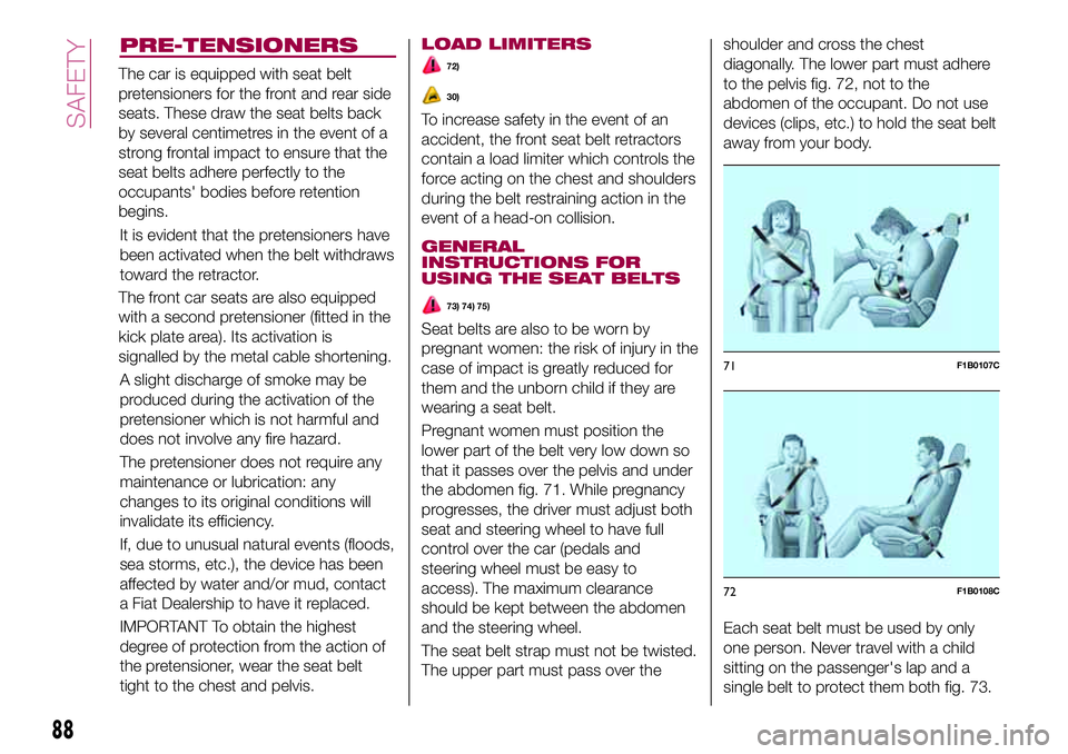
Pregnant women must position the
lower part of the belt very low down so
that it passes over the pelvis and under
the abdomen fig. 71. While pregnancy
progresses, the driver must adjust both
seat and steering wheel to have full
control over the car (pedals and
steering wheel must be easy to
access). The maximum clearance
should be kept between the abdomen
and the steering wheel.
The seat belt strap must not be twisted.
The upper part must pass over theshoulder and cross the chest
diagonally. The lower part must adhere
to the pelvis fig. 72, not to the
abdomen of the occupant. Do not use
devices (clips, etc.) to hold the seat belt
away from your body.
Each seat belt must be used by only
one person. Never travel with a child
sitting on the passenger's lap and a
single belt to protect them both fig. 73.
71F1B0107C
72F1B0108C
88
SAFETY
The car is equipped with seat belt
pretensioners for the front and rear side
seats. These draw the seat belts back
by several centimetres in the event of a
strong frontal impact to ensure that the
seat belts adhere perfectly to the
occupants' bodies before retention
begins.
The front car seats are also equipped
with a second pretensioner (fitted in the
kick plate area). Its activation is
signalled by the metal cable shortening.
Page 122 of 284
“Kick-Down” function
To resume speed quickly, when the
accelerator pedal is pressed fully, the
transmission control system downshifts
(kick-down function).
IMPORTANT When driving on roads
with poor grip conditions (snow, ice,
etc.) avoid activating the kick-down
function.
Gearshifting suggestion
With the transmission in automatic
mode (selector lever in position D),
when gearshifting is required by the
paddles on the steering wheel (where
provided), the system shifts to
"Sequential mode" ("Autostick"),
displaying the engaged gear for about
5 seconds.
When this time has elapsed, if the
paddles are not operated anymore, the
system goes back to the automatic
mode (D), with following displaying.
AUTOSTICK - Sequential
mode
In the case of frequent gearshifting (e.g.
when the vehicle is driven with a heavy
load, on slopes, with strong headwind
or when towing heavy trailers), it is
recommended to use the Autostick
(sequential shifting) mode to select and
keep a lower fixed ratio.In these conditions, using a lower gear
improves vehicle performance and
prolongs the transmission's life, limiting
gearshifting and preventing overheating.
It is possible to shift from position D
(Drive) to the sequential mode
regardless of vehicle speed.
Activation
With gear lever in position D (Drive), to
activate the sequential drive mode,
move the lever to the left (– and +
indication of the trim). The gear
engaged will be shown on the display.
Gearshifting is made by moving the
gear lever forwards, towards symbol –
or backwards, towards symbol +.
Off
To deactivate the sequential driving
mode, bring the gear lever back to
position D (Drive), automatic mode.
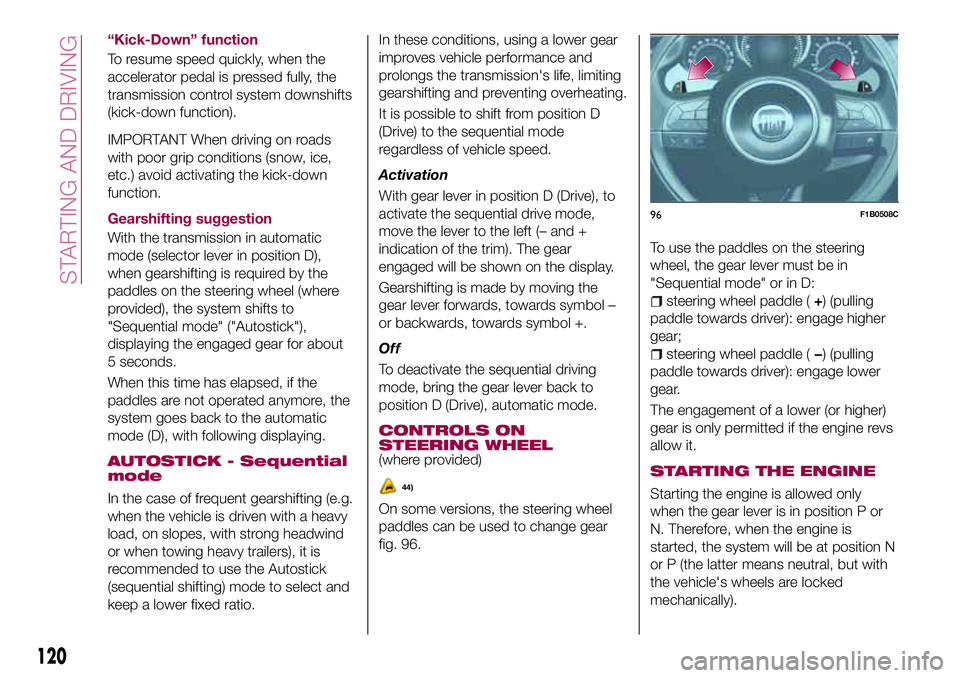
CONTROLS ON
STEERING WHEEL
(where provided)
On some versions, the steering wheel
paddles can be used to change gear
fig. 96.To use the paddles on the steering
wheel, the gear lever must be in
"Sequential mode" or in D:
steering wheel paddle (+) (pulling
paddle towards driver): engage higher
gear;
steering wheel paddle (−) (pulling
paddle towards driver): engage lower
gear.
The engagement of a lower (or higher)
gear is only permitted if the engine revs
allow it.
STARTING THE ENGINE
Starting the engine is allowed only
when the gear lever is in position P or
N. Therefore, when the engine is
started, the system will be at position N
or P (the latter means neutral, but with
the vehicle's wheels are locked
mechanically).
96F1B0508C
120
STARTING AND DRIVING
44)
Page 128 of 284
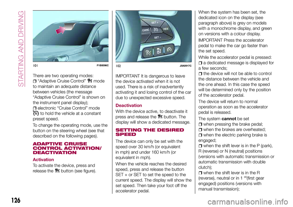
There are two operating modes:
“Adaptive Cruise Control”mode
to maintain an adequate distance
between vehicles (the message
“Adaptive Cruise Control” is shown on
the instrument panel display);
electronic “Cruise Control” mode
to hold the vehicle at a constant
preset speed.
To change the operating mode, use the
button on the steering wheel (see that
described on the following pages).
ADAPTIVE CRUISE
CONTROL ACTIVATION/
DEACTIVATION
Activation
To activate the device, press and
release the
button (see figure).
IMPORTANT It is dangerous to leave
the device activated when it is not
used. There is a risk of inadvertently
activating it and losing control of the car
due to unexpected excessive speed.
Deactivation
With the device active, to deactivate it
press and release the
button. The
display will show a dedicated message.
SETTING THE DESIRED
SPEED
The device can only be set with the
speed over 30 km/h (or equivalent
in mph) and under 160 km/h (or
equivalent in mph).
When the vehicle reaches the desired
speed, press and release the button
SET + or SET to set the speed to the
current speed. The display will show the
set speed. Then take your foot off the
accelerator pedal.When the system has been set, the
dedicated icon on the display (see
paragraph above) is grey on models
with a monochrome display, and green
on versions with a colour display.
IMPORTANT Press the accelerator
pedal to make the car go faster than
the set speed.
While the accelerator pedal is pressed:
a dedicated message is displayed for
a few seconds;
the device will not be able to control
the distance between the vehicle and
the one ahead. In this case the speed
will be determined only by the position
of the accelerator pedal.
The device will return to normal
operation as soon as the accelerator
pedal is released.
The systemcannotbe set
when pressing the brake pedal;
when the brakes are overheated;
when the electric parking brake is
engaged;
when the shift lever is in the P (park),
R (reverse) or N (neutral) positions
(versions with automatic transmission or
automatic transmission with double
clutch);
when the shift lever is in the R
(reverse), neutral or in 1st(first gear
engaged) positions (versions with
manual transmission);
101F1B0096C102J0A0917C
126
STARTING AND DRIVING
Page 157 of 284
WARNING
139)If the replaced fuse blows again,
contact a Fiat Dealership.
140)Never replace a fuse with another
with a higher amp rating; DANGER OF
FIRE
141)If a fuse NOT indicated in this or the
previous page is used, contact a Fiat
Dealership.
142)Before replacing a fuse, make sure
that the ignition device is at STOP, that the
key, if mechanical, has been removed and
that all devices are switched off and/or
disconnected.
IMPORTANT
66)Never replace a fuse with metal wires
or anything else.
67)If it is necessary to wash the engine
compartment, take care not to directly hit
the fuse box and the window wiper motor
with the water jet.
CHANGING A WHEEL
JACK
150) 151)
Please note that:
the jack weight is 2.8 kg;
the jack requires no adjustment;
the jack cannot be repaired and in
the event of a fault it must be replaced
by another genuine one;
no tool other than its cranking device
may be fitted on the jack.
Maintenance
prevent any dirt from depositing on
the "worm screw";
keep the "worm screw" lubricated;
never modify the jack.
Conditions for non-use
temperatures below −40°C;
on sandy or muddy ground;
on uneven ground;
on steep roads;
in extreme weather conditions:
thunderstorms, typhoons, hurricanes,
blizzards, storms, etc...
in direct contact with the engine or
for repairs under the car;
on boats.
CHANGING PROCEDURE
143) 144) 145) 146) 147) 148) 149)
Proceed as follows:
stop the vehicle in a position that is
not dangerous for oncoming traffic
where you can change the wheel safely.
The ground should be flat if possible,
and sufficiently firm;
stop the engine, engage the hazard
warning lights and the electric parking
brake;
engage first gear or reverse or, for
versions with automatic transmission,
move the lever to position P (Park);
wear the reflective safety jacket
(compulsory by law in certain countries)
before getting out of the vehicle;
open the boot and position the
reconfigurable load platform in an
inclined position (see "Boot" in the
"Knowing your vehicle" chapter);
take the tool bag provided, which is
secured to the luggage compartment
cover with specific fastenings. This bag
contains fig. 128: jack A; screwdriver B;
adaptor C for refuelling in the event of
an emergency; pin D for centring the
wheel (where provided, to be used in
the spare wheel fitting procedure);
special anti-theft nut E (where provided,
to be used in the wheel stud bolt
fitting/removal procedure); wedge F
wheels and the vehicle;
155
(where provided) for blocking the