tow FIAT 500X 2017 Owner handbook (in English)
[x] Cancel search | Manufacturer: FIAT, Model Year: 2017, Model line: 500X, Model: FIAT 500X 2017Pages: 284, PDF Size: 11.14 MB
Page 15 of 284
if 30 minutes pass with the vehicle
stationary (versions with manual
gearbox) or with the gear lever at P
(Park) (versions with automatic
transmission) and the engine off, the
ignition device will automatically move
to the STOP position.
NOTE With engine started, it is possible
to go away from the vehicle taking the
electronic key with you. The engine will
still be running. The vehicle will indicate
the absence of the key on board when
the door is closed.
For more information on the engine
start-up, see the description in the
"Starting the engine" paragraph, in the
"Starting and driving" chapter.
4) 5)
STEERING LOCK
Activation
Versions with key without remote
control: with the device at STOP,
remove the key and turn the steering
wheel until it locks.
IMPORTANT If the ignition key has been
moved from the MAR to the STOP
position, the steering lock cannot
engage until the key is removed from
the ignition device.
Versions with electronic key: the
steering lock engages when the driver
door is opened, with the ignition devicebutton at STOP and speed below
3 km/h.
Deactivation
Versions with key without remote
control: slightly moving the steering
wheel, turn the key to the MAR
position.
Versions with electronic key: the
steering lock disengages when the
ignition device is pressed and the
electronic key is recognised.
6) 7)
WARNING
2)If the ignition device has been tampered
with (e.g. an attempted theft), have it
checked by a Fiat Dealership before driving
again.
3)Always take the key with you when you
leave your vehicle to prevent someone
from accidentally operating the controls.
Remember to engage the electric parking
brake. Never leave children unattended in
the vehicle.
4)It is absolutely forbidden to carry out any
after-market operation involving steering
system or steering column modifications
(e.g. installation of anti-theft device) that
could adversely affect performance,
invalidate the warranty, cause serious
safety problems and also result in the car
not meeting type-approval requirements.5)Never extract the mechanical key while
the vehicle is moving. The steering wheel
will automatically lock as soon as it is
turned. This holds true for cars being
towed as well.
6)Before exiting the vehicle, ALWAYS
engage the parking brake, steer the
wheels, engage the first gear if uphill and
the reverse if downhill. On versions with
automatic transmission, bring the gear
lever to P (Park) and press the ignition
device to bring it to STOP. If the vehicle is
parked on a steep slope, chock the wheels
with wedges or stones. When leaving the
car, always lock all the doors by pressing
the dedicated button on the handle (see
"Keyless Entry" in the paragraph "Doors").
7)For versions equipped with the Full
Keyless System, do not leave the
electronic key inside or near the car or in a
place accessible to children. Do not leave
the vehicle with the ignition device in MAR
position. A child could activate the electric
window winders, other controls or even
start the vehicle.
13
Page 16 of 284
FIAT CODE
The Fiat Code system prevents
unauthorised use of the vehicle,
disabling engine starting.
The system does not need to be
enabled/activated: operation is
automatic, regardless of the fact that
the vehicle's doors are locked or
unlocked.
When the ignition device is set to MAR,
the Fiat Code system identifies the
code transmitted by the key. If the code
is recognised as valid, the Fiat Code
system enables engine starting.
When the ignition device is brought
back to STOP, the Fiat Code system
deactivates the control unit controlling
the engine, thus preventing its starting.
For the correct engine starting
procedures, see the instructions in the
"Starting the engine" paragraph,
"Starting and driving" chapter.IRREGULAR OPERATION
If, during starting, the key code is not
correctly recognised, the
icon is
displayed on the instrument panel (see
the instructions in the "Warning lights
and messages" paragraph, "Knowing
the instrument panel" chapter). This
condition leads to the engine switching
off after 2 seconds. In this case, bring
the ignition device to STOP and then to
MAR; if it is still blocked, try with the
other keys provided. If it is still not
possible to start the engine, contact a
Fiat Dealership.
If the
icon is displayed while
driving, this means that the system is
running a self-diagnosis (e.g. due to a
voltage drop). If the display persists,
contact a Fiat Dealership.
ALARM
Activation of the alarm triggers the
acoustic warning and the direction
indicators.
IMPORTANT The alarm is adapted by
the Manufacturer to meet the
requirements of the various countries
where the vehicle is marketed.
SWITCHING ON THE
ALARM
(where provided)
With the doors, bonnet and tailgate
closed and the ignition device turned to
STOP, point the key with remote control
or electronic key towards the vehicle
and press and release the
"FIAT"
button.
For versions with electronic key, the
alarm can also be engaged by pressing
the "door lock" button, located on the
door external handle. For further
information refer to the Keyless Entry
paragraph, a few pages further on.
The system emits a visual and acoustic
signal (where provided) and enables
door locking.
With the alarm on, warning light A
fig. 7 flashes on the instrument panel.
14
GETTING TO KNOW YOUR CAR
Page 28 of 284
If the value set on the Menu is different
from 0, the lights can be switched of for
the predetermined time by taking the
ring from position
(with the engine
running) to positionO(with the engine
off).
The function can be activated
automatically on versions with dusk
sensor: turn the ring to theAUTO
position with the engine running. The
dipped beam headlights will be turned
on if the sensor detects a low level of
light. The headlights off delay is
activated automatically when the engine
is switched off with the headlights on
for the time selected in the Menu.
Deactivation
If the function is activated by using the
left steering wheel stalk, the function
can be deactivated by holding the left
lever in "main beam flashing" mode for
longer than 2 seconds or by waiting for
the deactivation time shown on the
display.
The function cannot be deactivated if it
is activated using the light line. The
headlights will be switched off at the
end of the set time.
Turning the ignition device to the AVV
position will deactivate the function.
MAIN BEAM HEADLIGHTS
With the light switch ring nut turned to
position
orAUTOpush the left
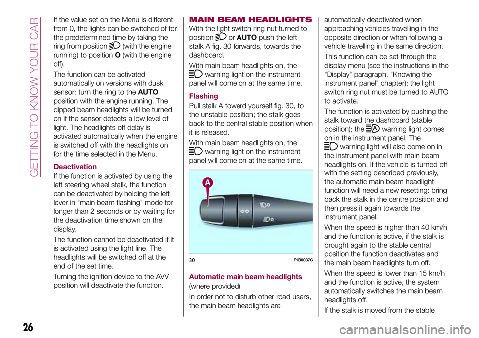
stalk A fig. 30 forwards, towards the
dashboard.
With main beam headlights on, the
warning light on the instrument
panel will come on at the same time.
Flashing
Pull stalk A toward yourself fig. 30, to
the unstable position; the stalk goes
back to the central stable position when
it is released.
With main beam headlights on, the
warning light on the instrument
panel will come on at the same time.
Automatic main beam headlights
(where provided)
In order not to disturb other road users,
the main beam headlights areautomatically deactivated when
approaching vehicles travelling in the
opposite direction or when following a
vehicle travelling in the same direction.
This function can be set through the
display menu (see the instructions in the
"Display" paragraph, "Knowing the
instrument panel" chapter); the light
switch ring nut must be turned to AUTO
to activate.
The function is activated by pushing the
stalk toward the dashboard (stable
position); the
warning light comes
on in the instrument panel. The
warning light will also come on in
the instrument panel with main beam
headlights on. If the vehicle is turned off
with the setting described previously,
the automatic main beam headlight
function will need a new resetting: bring
back the stalk in the centre position and
then press it again towards the
instrument panel.
When the speed is higher than 40 km/h
and the function is active, if the stalk is
brought again to the stable central
position the function deactivates and
the main beam headlights turn off.
When the speed is lower than 15 km/h
and the function is active, the system
automatically switches the main beam
headlights off.
If the stalk is moved from the stable
30F1B0037C
26
GETTING TO KNOW YOUR CAR
Page 29 of 284
central position and pushed again
towards the dashboard in the stable
position, this is interpreted as a request
for fixed main beam headlights: the
warning light comes on in the
instrument panel and the main beam
headlights turn on until vehicle speed
exceeds 40 km/h again. When this
threshold is exceeded the function
activates again automatically and the
warning light comes on again in
the instrument panel.
To deactivate this function, rotate the
light switch ring nut to the
position.
DIRECTION INDICATORS
Bring left stalk A fig. 30 to the (stable)
position:
upwards: activates the right direction
indicator;
downwards: activates the left direction
indicator.
The
orwarning light respectively
will flash on the instrument panel.
The direction indicators switch off
automatically when the steering wheel
is straightened or when the daytime
running lights (DRL)/parking lights are
activated."Lane Change" function
If you wish to signal a lane change while
running, place the left stalk in the
unstable position for less than half a
second.
The direction indicator on the side
selected will flash five times and then
switch off automatically.
HEADLIGHT ALIGNMENT
ADJUSTMENT
Headlight alignment corrector
The headlight alignment corrector
operates with ignition device at MAR
and dipped headlights on.
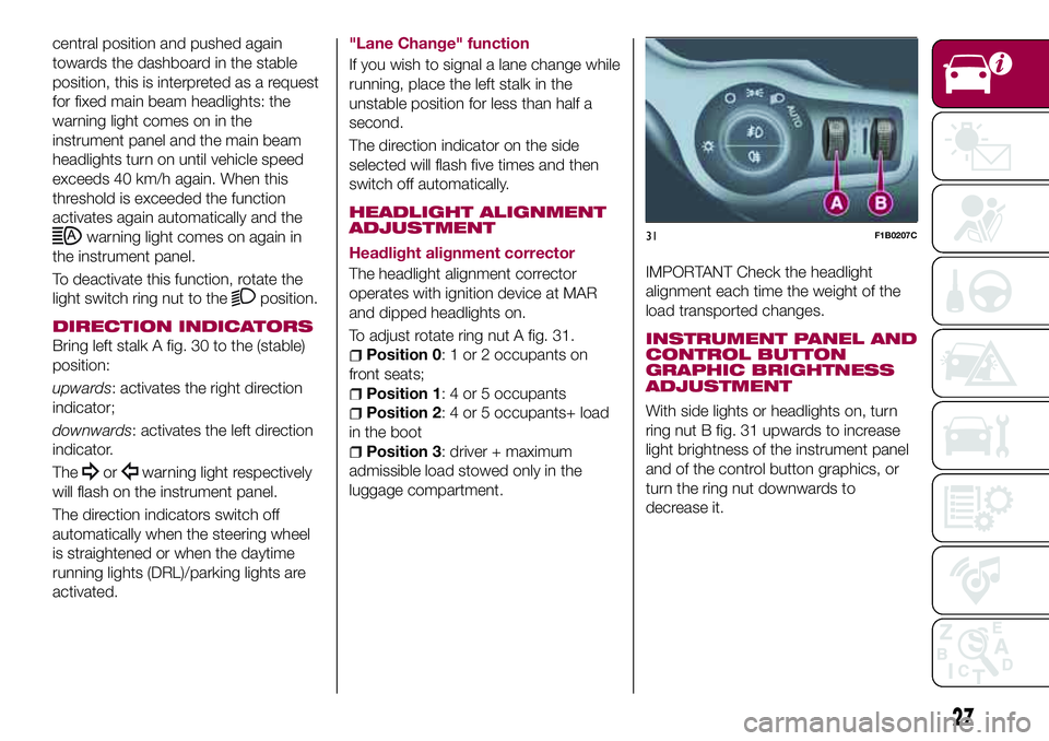
To adjust rotate ring nut A fig. 31.
Position 0: 1 or 2 occupants on
front seats;
Position 1: 4 or 5 occupants
Position 2: 4 or 5 occupants+ load
in the boot
Position 3: driver + maximum
admissible load stowed only in the
luggage compartment.
IMPORTANT Check the headlight
alignment each time the weight of the
load transported changes.
INSTRUMENT PANEL AND
CONTROL BUTTON
GRAPHIC BRIGHTNESS
ADJUSTMENT
With side lights or headlights on, turn
ring nut B fig. 31 upwards to increase
light brightness of the instrument panel
and of the control button graphics, or
turn the ring nut downwards to
decrease it.
31F1B0207C
27
Page 31 of 284
WINDSCREEN/REAR
WINDOW WIPER
Operation is only possible with the
ignition device at MAR.
WINDSCREEN WIPER/
WASHER
Operation
7) 8)
20)
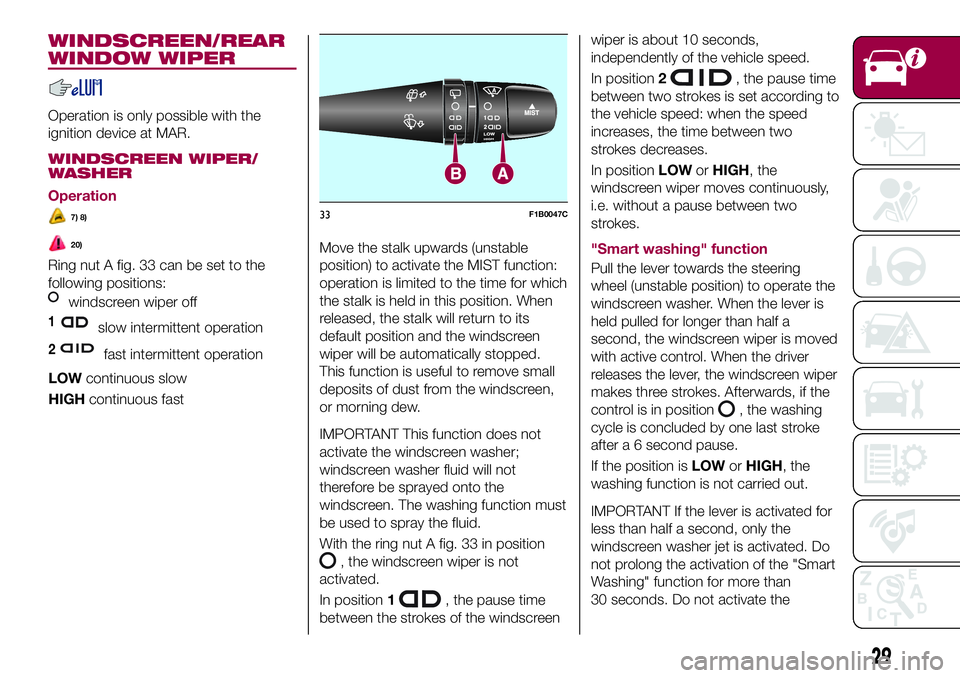
Ring nut A fig. 33 can be set to the
following positions:
windscreen wiper off
1slow intermittent operation
2fast intermittent operation
LOWcontinuous slow
HIGHcontinuous fastMove the stalk upwards (unstable
position) to activate the MIST function:
operation is limited to the time for which
the stalk is held in this position. When
released, the stalk will return to its
default position and the windscreen
wiper will be automatically stopped.
This function is useful to remove small
deposits of dust from the windscreen,
or morning dew.
IMPORTANT This function does not
activate the windscreen washer;
windscreen washer fluid will not
therefore be sprayed onto the
windscreen. The washing function must
be used to spray the fluid.
With the ring nut A fig. 33 in position
, the windscreen wiper is not
activated.
In position1
, the pause time
between the strokes of the windscreenwiper is about 10 seconds,
independently of the vehicle speed.
In position2
, the pause time
between two strokes is set according to
the vehicle speed: when the speed
increases, the time between two
strokes decreases.
In positionLOWorHIGH, the
windscreen wiper moves continuously,
i.e. without a pause between two
strokes.
"Smart washing" function
Pull the lever towards the steering
wheel (unstable position) to operate the
windscreen washer. When the lever is
held pulled for longer than half a
second, the windscreen wiper is moved
with active control. When the driver
releases the lever, the windscreen wiper
makes three strokes. Afterwards, if the
control is in position
, the washing
cycle is concluded by one last stroke
after a 6 second pause.
If the position isLOWorHIGH, the
washing function is not carried out.
IMPORTANT If the lever is activated for
less than half a second, only the
windscreen washer jet is activated. Do
not prolong the activation of the "Smart
Washing" function for more than
30 seconds. Do not activate the
MIST1
2LO
WH
IGH
A
33F1B0047C
29
Page 34 of 284
Push the stalk towards the dashboard
(rocking position) to activate the rear
window washer jet. Keep pushing the
lever to automatically activate both the
rear window washer jet and the rear
window wiper with a single movement.
Releasing the stalk will activate three
strokes, as described for the
windscreen wiper. If the position is
(rear window wiper stopped), after a
6 second pause, the washing cycle is
completed by a single stroke. The
smart wash cycle will not be performed
if the position is
.
If the driver makes a washing request
for longer than 30 seconds, the
washing cycle will be inhibited, as
described in the "Smart Wash"
paragraph.
WARNING
20)If the window needs to be cleaned,
make sure the device is deactivated or the
ignition button and the key are on STOP.
IMPORTANT
7)Never use the windscreen wipers to
remove layers of snow or ice from the
windscreen. In such conditions, the
windscreen wiper may be subjected to
excessive stress and the motor cut-out
switch, which prevents operation for a few
seconds, may intervene. If operation is not
subsequently restored, even after restarting
the engine, contact a Fiat Dealership.
8)Do not operate the windscreen wiper
with the blades lifted from the windscreen.
9)Do not activate the rain sensor when
washing the car in an automatic car wash.
10)Make sure the device is switched off if
there is ice on the windscreen.
32
GETTING TO KNOW YOUR CAR
Page 44 of 284
BOOT INITIALISATION
IMPORTANT If the battery is
disconnected or the protection fuse
blows, the boot opening/closing
mechanism must be reinitialised as
follows:
close all the doors and the boot;
press the"FIAT" button on the
remote control;
press thebutton on the remote
control.
LOAD COMPARTMENT
Reconfigurable load platform
12)
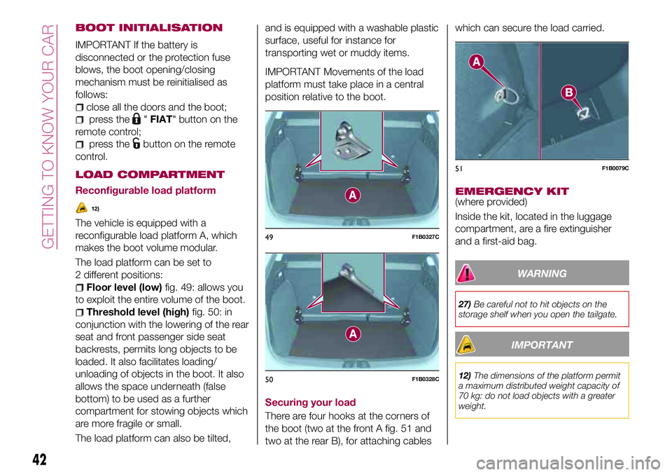
The vehicle is equipped with a
reconfigurable load platform A, which
makes the boot volume modular.
The load platform can be set to
2 different positions:
Floor level (low)fig. 49: allows you
to exploit the entire volume of the boot.
Threshold level (high)fig. 50: in
conjunction with the lowering of the rear
seat and front passenger side seat
backrests, permits long objects to be
loaded. It also facilitates loading/
unloading of objects in the boot. It also
allows the space underneath (false
bottom) to be used as a further
compartment for stowing objects which
are more fragile or small.
The load platform can also be tilted,and is equipped with a washable plastic
surface, useful for instance for
transporting wet or muddy items.
IMPORTANT Movements of the load
platform must take place in a central
position relative to the boot.
Securing your load
There are four hooks at the corners of
the boot (two at the front A fig. 51 and
two at the rear B), for attaching cableswhich can secure the load carried.
EMERGENCY KIT(where provided)
Inside the kit, located in the luggage
compartment, are a fire extinguisher
and a first-aid bag.
WARNING
27)Be careful not to hit objects on the
storage shelf when you open the tailgate.
IMPORTANT
12)The dimensions of the platform permit
a maximum distributed weight capacity of
70 kg: do not load objects with a greater
weight.
49F1B0327C
50F1B0328C
51F1B0079C
42
GETTING TO KNOW YOUR CAR
Page 76 of 284
39)The ESC system cannot prevent
accidents, including those due to excessive
speed on corners, driving on low-grip
surfaces or aquaplaning.
40)The capability of the ESC system must
never be tested irresponsibly and
dangerously, in such a way as to
compromise personal safety and the safety
of others.
41)For the correct operation of the ESC
system, the tyres must necessarily be of
the same make and type on all wheels, in
perfect condition and, above all, of the
prescribed type and size.
42)ESC performance features must not
induce the driver to take unnecessary or
unwarranted risks. Your driving style must
always be suited to the road conditions,
visibility and traffic. The driver is, in any
case, responsible for safe driving.
43)For the correct operation of the TC
system, the tyres must of necessity be the
same make and type on all wheels, in
perfect condition and, above all, of the
prescribed type and dimensions.
44)TC performance features must not
induce the driver to take unnecessary or
unwarranted risks. Your driving style must
always be suited to the road conditions,
visibility and traffic. The driver is, in any
case, responsible for safe driving.
45)The TC system cannot overrule the
natural laws of physics, and cannot
increase the grip available according to the
condition of the road.
46)The TC system cannot prevent
accidents, including those due to excessive
speed on corners, driving on low-grip
surfaces or aquaplaning.47)The capability of the TC must never be
tested irresponsibly and dangerously, in
such a way as to compromise personal
safety and the safety of others.
48)The PBA system cannot overrule the
natural laws of physics, and cannot
increase the grip available according to the
condition of the road.
49)The PBA system cannot prevent
accidents, including those due to excessive
speed on corners, driving on low-grip
surfaces or aquaplaning.
50)The capability of the PBA system must
never be tested irresponsibly and
dangerously, in such a way as to
compromise the safety of the driver, the
other occupants of the vehicle or any other
road user.
51)The Hill Hold Control system is not a
parking brake; therefore, never leave the
vehicle without having engaged the electric
parking brake, turned the engine off and
engaged first gear, so that it is parked in
safe conditions (for further information read
the "Parking" paragraph in the "Starting
and driving" chapter).
52)There may be situations on small
gradients (less than 8%), with vehicle
laden, in which the Hill Hold Control system
may not activate, causing a slight reversing
motion and increasing the risk of collision
with another vehicle or object. The driver is,
in any case, responsible for safe driving.
53)DST is an aid for driving and does not
relieve the driver of responsibility for driving
the vehicle.
54)The performance of a vehicle with ERM
must never be tested in imprudent or
dangerous ways, with the possibility of
putting the safety of the driver or other
people at risk.55)When towing trailers, the utmost
caution at the wheel is recommended.
Never exceed the maximum permitted
loads (see the description in the "Weights"
paragraph in the "Technical Specifications"
chapter).
56)The TSC system cannot prevent
swerving for all trailers. If the system
activates during driving, reduce the speed,
stop the vehicle in a safe place and arrange
the load correctly to prevent the trailer from
swerving.
74
SAFETY
Page 78 of 284
automatic transmission), or with vehicle
at a standstill and electric parking brake
engaged (versions with manual
gearbox).
The detection area of the system
covers about a lane on both sides of
the vehicle (around 3 metres).
This area begins from the door mirror
and extends for about 6 metres
towards the rear part of the vehicle.
When the sensors are active the system
monitors the detection areas on both
sides of the vehicle and warns the
driver about the possible presence of
vehicles in these areas.
While driving the system monitors the
detection area from three different input
points (side, rear and front) to check
whether a signal needs to be sent to
the driver. The system can detect the
presence of a vehicle in one of these
three areas.
IMPORTANT The system does not
signal the presence of fixed object (e.g.
safety barriers, poles, walls, etc.).
However, in some circumstances, the
system may activate in the presence of
these objects. This is normal and does
not indicate a system malfunction.
IMPORTANT The system does not
warn the driver about the presence ofvehicles coming from the opposite
direction, in the adjacent lanes.
57)
Important
If a trailer is hitched to the vehicle, the
system must be manually deactivated
using the relevant menu, in order to
avoid false warnings.
For the system to operate correctly, the
rear bumper area where the radar
sensors are located must stay free from
snow, ice and dirt gathered from the
road surface.
Do not cover the rear bumper area
where the radar sensors are located
with any object (e.g. adhesives, bike
rack, etc.).
Rear view
The system detects vehicles coming
from the rear part of your vehicle on
both sides and entering the rear
detection area with a difference in
speed of less than 50 km/h with
respect to your vehicle.
Overtaking vehicles
If another vehicle is overtaken slowly
(with a difference in speed of less than
about 25 km/h) and this stays in the
blind spot for about 1.5 seconds, the
warning light on the door mirror of the
corresponding side lights up.If the difference in speed between the
two vehicles is greater than about
25 km/h, the warning light does not
light up.
RCP (Rear Cross Path detection)
system
This system helps the driver during
reverse manoeuvres in the case of
reduced visibility.
The RCP system monitors the rear
detection areas on both sides of the
vehicle, to detect objects moving
towards the sides of the vehicle at a
minimum speed between about 1 km/h
and 3 km/h and objects moving at a
maximum speed of 35 km/h, as
generally happens in parking areas.
The system activation is signalled to the
driver by means of a visual and acoustic
warning.
IMPORTANT If the sensors are covered
by objects or vehicles, the system will
not warn the driver.
Operating mode
The system can be activated/
deactivated by operating on the display
Menu, or via theUconnect™system
(for further information see the
dedicated Supplement).
76
SAFETY
Page 85 of 284
WARNING
57)The system is an aid for vehicle driving,
it DOES NOT warn the driver about
incoming vehicles outside of the detection
areas. The driver must always maintain a
sufficient level of attention to the traffic and
road conditions and for controlling the
trajectory of the vehicle.
58)The system is an aid for the driver, who
must always pay full attention while driving.
The responsibility always rests with the
driver, who must take into account the
traffic conditions in order to drive in
complete safety. The driver must always
maintain a safe distance from the vehicle in
front.
59)If the driver depresses the brake pedal
fully or carries out a fast steering during
system operation, the automatic braking
function may stop (e.g. to allow a possible
manoeuvre to avoid the obstacle).
60)The system intervenes on vehicles
travelling in the same lane. People, animals
and things (e.g. pushchairs) are not taken
into consideration.
61)If the car must be placed on a roller
bench for maintenance interventions or if it
is washed in an automatic roller washing
tunnel with an obstacle in the front part
(e.g. another car, a wall or another
obstacle), the system may detect its
presence and activate. In this case the
system must be deactivated through the
settings of theUconnect™system.
62)If the iTPMS system signals a pressure
decrease on the tyres, it is recommended
to check the pressure on all four tyres.63)The iTPMS does not relieve the driver
from the obligation to check the tyre
pressure every month; it is not even to be
considered a replacing system for
maintenance or a safety system.
64)Tyre pressure must be checked with
tyres cold. Should it become necessary for
whatever reason to check pressure with
warm tyres, do not reduce pressure even
though it is higher than the prescribed
value, but repeat the check when tyres are
cold
65)The iTPMS cannot indicate sudden tyre
pressure drops (e.g. if a tyre bursts). In this
case, stop the vehicle, braking with caution
and avoiding abrupt steering.
66)The system only warns that the tyre
pressure is low: it is not able to inflate
them.
67)Insufficient tyre inflation increases fuel
consumption, reduces the tread duration
and may affect the capacity to drive safely.
IMPORTANT
21)The system may have limited or absent
operation due to weather conditions such
as: heavy rain, hail, thick fog, heavy snow.
22)The section of the bumper before the
sensor must not be covered with
adhesives, auxiliary headlights or any other
object.
23)System intervention might be
unexpected or delayed when other vehicles
transport loads projecting from the side,
above or from the rear, with respect to the
normal size of the vehicle.24)Operation can be adversely affected by
any structural change made to the vehicle,
such as a modification to the front
geometry, tyre change, or a heavier load
than the standard load of the vehicle.
25)Incorrect repairs made on the front part
of the vehicle (e.g. bumper, chassis) may
alter the position of the radar sensor, and
adversely affect its operation. Go to a Fiat
Dealership for any operation of this type.
26)Do not tamper with nor carry out any
intervention on the radar sensor or on the
camera on the windscreen. In the event of
a sensor failure, contact a Fiat Dealership.
27)When towing a trailer (with modules
installed after purchasing the vehicle), a
vehicle or during loading manoeuvres on a
vehicle transporter (or in vehicle for
transport), the system must be deactivated
via theUconnect™system.
28)Do not wash with high-pressure jets in
the bumper lower area: in particular do not
operate on the system's electrical
connector.
29)Be careful in the case of repairs and
new paintings in the area around the
sensor (panel covering the sensor on the
left side of the bumper). In the event of a
frontal impact the sensor may automatically
deactivate and display a warning to indicate
that the sensor needs to be repaired. Even
without a malfunction warning, deactivate
the system operation if you think that the
position of the radar sensor has changed
(e.g. due to low-speed frontal impact as
during parking manoeuvres). In these
cases, go to a Fiat Dealership to have the
radar sensor realigned or replaced.
83