dashboard FIAT 500X 2018 Owner handbook (in English)
[x] Cancel search | Manufacturer: FIAT, Model Year: 2018, Model line: 500X, Model: FIAT 500X 2018Pages: 276, PDF Size: 7.08 MB
Page 157 of 276
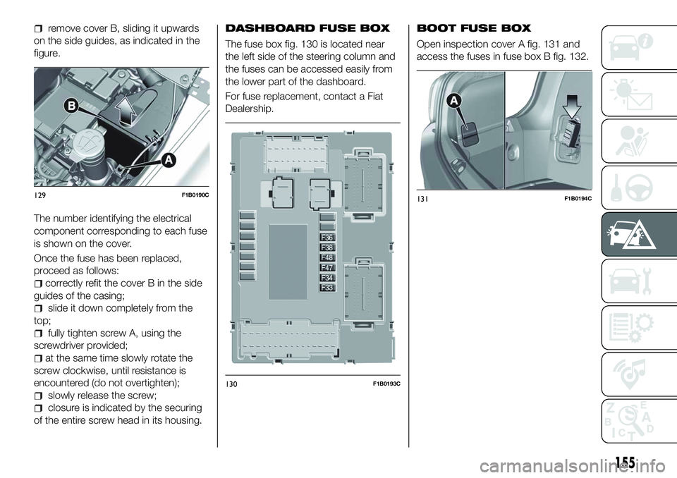
remove cover B, sliding it upwards
on the side guides, as indicated in the
figure.
The number identifying the electrical
component corresponding to each fuse
is shown on the cover.
Once the fuse has been replaced,
proceed as follows:
correctly refit the cover B in the side
guides of the casing;
slide it down completely from the
top;
fully tighten screw A, using the
screwdriver provided;
at the same time slowly rotate the
screw clockwise, until resistance is
encountered (do not overtighten);
slowly release the screw;
closure is indicated by the securing
of the entire screw head in its housing.
DASHBOARD FUSE BOX
The fuse box fig. 130 is located near
the left side of the steering column and
the fuses can be accessed easily from
the lower part of the dashboard.
For fuse replacement, contact a Fiat
Dealership.
BOOT FUSE BOX
Open inspection cover A fig. 131 and
access the fuses in fuse box B fig. 132.
129F1B0190C
130F1B0193C
131F1B0194C
155
Page 159 of 276
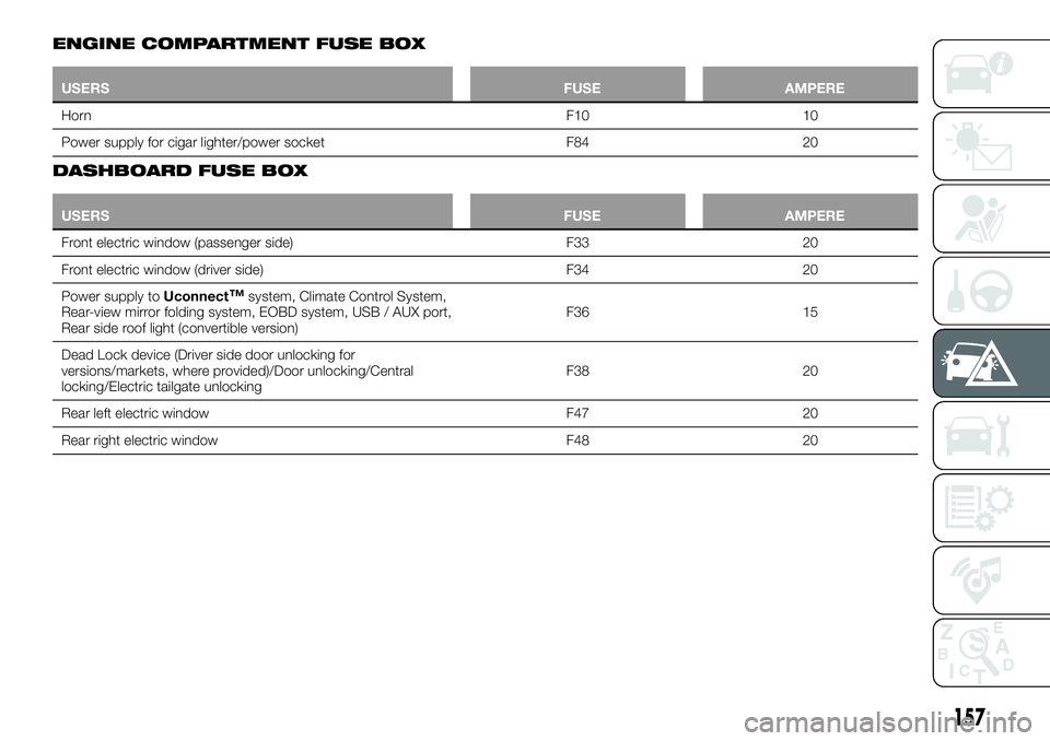
ENGINE COMPARTMENT FUSE BOX
USERSFUSE AMPERE
Horn F10
10
Power supply for cigar lighter/power socket F8420
DASHBOARD FUSE BOX
USERS FUSE AMPERE
Front electric window (passenger side) F3320
Fr
ont electric window (driver side) F3420
Power supply to Uconnect
™system, Climate Control System,
Rear-view mirror folding system, EOBD system, USB / AUX port,
Rear side roof light (convertible version) F36 15
Dead Lock device (Driver side door unlocking for
versions/markets, where provided)/Door unlocking/Central
locking/Electric tailgate unlocking F38 20
Rear left electric window F47 20
Rear right electric window F48 20
157
Page 165 of 276
153)Never tamper with the inflation valve.
Never introduce tools of any kind between
the rim and the tyre. Check tyre and
space-saver wheel pressures regularly,
complying with the values given in the
"Technical specifications" chapter.
154) The jack is a tool developed and
designed only for changing a wheel, if a
tyre gets punctured or damaged, on the
vehicle with which it is supplied or on other
vehicles of the same model. Any other use,
e.g. to jack up other vehicle models or
different things, is strictly prohibited. Never
use it to carry out maintenance or repairs
under the vehicle or to change
summer/winter wheels and vice versa: we
advise you to contact a Fiat Dealership.
Never go under the raised vehicle: use it
only in the positions indicated. Do not use
the jack for loads higher than the one
shown on its label. Never start the engine
with car raised. If the car is raised more
than necessary, everything can become
more unstable, with the risk of the car
dropping violently. Thus, lift the car only as
needed in order to access the space-saver
spare wheel.
155) When turning the jack handle make
sure that it can turn freely without scraping
your hand against the ground. The moving
components of the jack ("worm screw" and
joints) can also cause injuries: do not touch
them. If you come into contact with
lubricating grease, clean yourself
thoroughly.FIX&GO AUTOMATIC
KIT
(where provided)
156) 157)
80)
DESCRIPTION
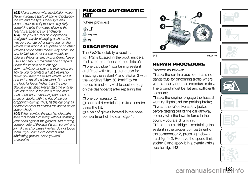
The Fix&Go quick tyre repair kit
fig. 142 is located in the boot, inside a
dedicated container and consists of:
one cartridge 1 containing sealant
and fitted with: transparent tube for
injecting the sealant 4 and sticker 3 with
the wording “Max. 80 km/h” to be
placed in a clearly visible position (e.g.
on the dashboard) after repairing the
tyre;
one compressor 2;
one leaflet containing instructions for
using the kit;
a pair of gloves located in the hose
compartment of the cartridge 4.
REPAIR PROCEDURE
Proceed as follows:
stop the car in a position that is not
dangerous for oncoming traffic where
you can carry out the procedure safely.
The ground must be flat and sufficiently
compact;
stop the engine, engage the hazard
warning lights and the parking brake;
wear the reflective safety jacket
before getting out of the car (anyway
comply with the laws in force in the
country you are driving in);
Insert the cartridge 1 containing the
sealant in the proper compartment of
the compressor 2, pressing it down
hard fig. 142. Remove the speed limit
sticker 3 and apply it in a clearly visible
position fig. 143;
142P2000158
163
Page 170 of 276
FUEL CUT-OFF
SYSTEM
DESCRIPTION
This intervenes in the case of an impact
causing:
the interruption of the fuel supply
with the engine consequently switching
off;
the automatic unlocking of the
doors;
turning on of the lights inside the
vehicle;
deactivation of climate control
system ventilation;
switching on of the hazard warning
lights (to deactivate the lights press the
button on the dashboard).
On some versions, the intervention of
the system is indicated by a message
shown on the display. In the same way,
a dedicated message on the display
warns the driver if system operation is
compromised.
IMPORTANT Carefully check the vehicle
for fuel leaks, for instance in the engine
compartment, under the vehicle or near
the tank area. After a collision, bring the
ignition device to STOP to prevent the
battery from running down. FUEL CUT-OFF SYSTEM
RESET
162)
To restore correct operation of the car,
carry out the following procedure (this
procedure must be started and
completed within less than 1 minute):
with direction indicator lever in
neutral position, turn the ignition device
to STOP;
turn the ignition device to MAR;
activate the right direction indicator
and then the left one;
activate the right direction indicator
and then the left one again;
deactivate the left direction indicator;
turn the ignition device to STOP and
then to MAR.
WARNING
162) If, after an impact, you smell fuel or
notice leaks from the fuel system, do not
reactivate the system to avoid the risk of
fire.
AUTOMATIC
TRANSMISSION -
LEVER UNLOCK
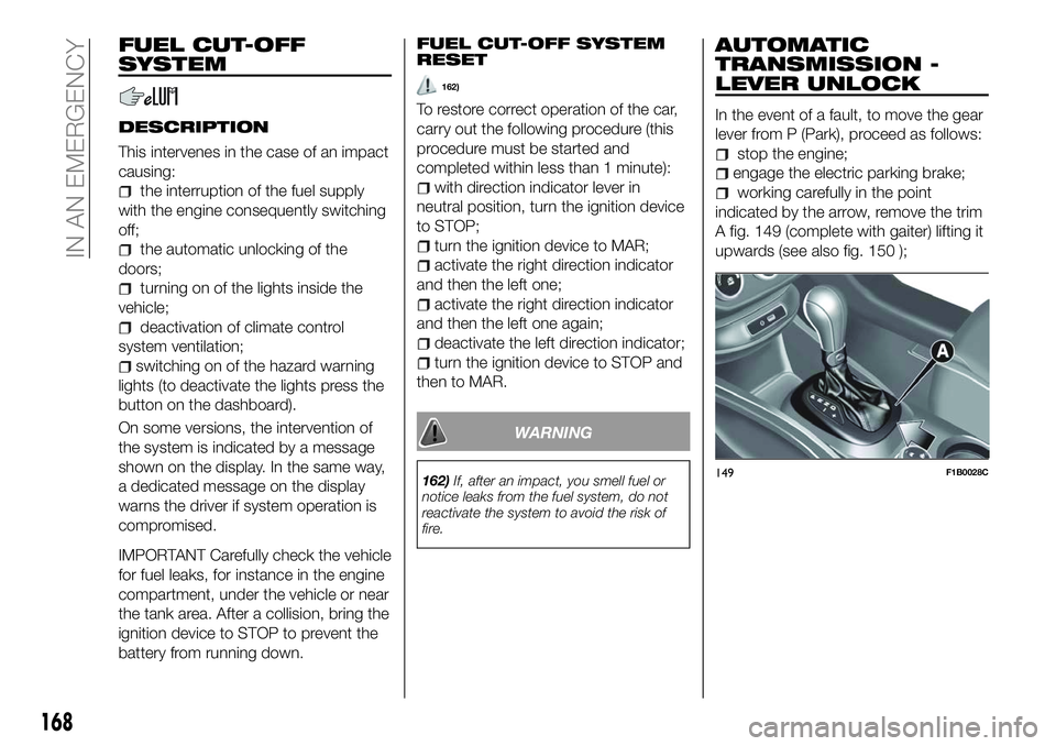
In the event of a fault, to move the gear
lever from P (Park), proceed as follows:
stop the engine;
engage the electric parking brake;
working carefully in the point
indicated by the arrow, remove the trim
A fig. 149 (complete with gaiter) lifting it
upwards (see also fig. 150 );
149F1B0028C
168
IN AN EMERGENCY
Page 207 of 276
PLASTIC AND COATED
PARTS
103)
Clean interior plastic parts with a damp
cloth (if possible made from microfibre),
and a solution of water and neutral,
non-abrasive detergent.
To clean oily or persistent stains, use
specific products free from solvents and
designed to maintain the original
appearance and colour of the
components.
Remove any dust using a microfibre
cloth, if necessary moistened with
water. The use of paper tissues is not
recommended as these may leave
residues.
GENUINE LEATHER
PARTS
(where provided)
Use only water and mild soap to clean
these parts. Never use alcohol or
alcohol-based products.
Before using a specific product for
cleaning interiors, make sure that it
does not contain alcohol and/or
alcohol-based substances.
WARNING
186)Never use flammable products, such
as petrol ether or rectified petrol to clean
the inside of the car. The electrostatic
charges which are generated by rubbing
during the cleaning operation may cause a
fire.
187) Do not keep aerosol cans in the car:
they might explode. Aerosol cans must not
be exposed to a temperature exceeding
50°C. When the vehicle is exposed to
sunlight, the internal temperature can
greatly exceed this value.
188) There must be no obstacles on the
floor underneath the pedals; make sure
that mats are always flat and do not
interfere with the pedals.
IMPORTANT
103) Never use alcohol, petrols and
derivatives to clean the dashboard and
instrument panel lens.
205
Page 209 of 276
IDENTIFICATION
DATA
VIN PLATE
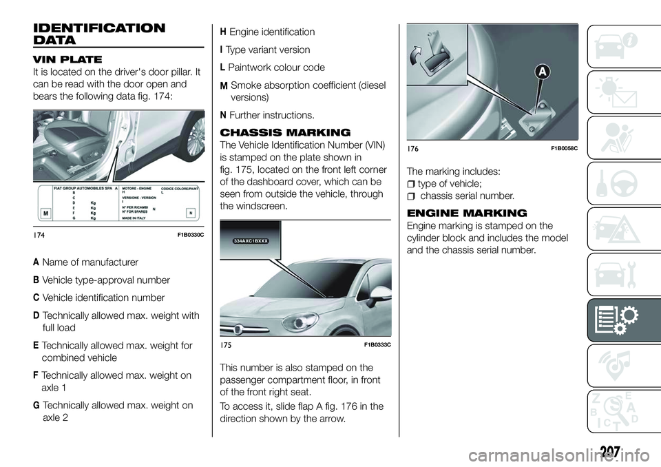
It is located on the driver's door pillar. It
can be read with the door open and
bears the following data fig. 174:
AName of manufacturer
BVehicle type-approval number
CVehicle identification number
DTechnically allowed max. weight with
full load
ETechnically allowed max. weight for
combined vehicle
FTechnically allowed max. weight on
axle 1
GTechnically allowed max. weight on
axle 2
HEngine identification
IType variant version
LPaintwork colour code
MSmoke absorption coefficient (diesel
versions)
NFurther instructions.
CHASSIS MARKING
The Vehicle Identification Number (VIN)
is stamped on the plate shown in
fig. 175, located on the front left corner
of the dashboard cover, which can be
seen from outside the vehicle, through
the windscreen.
This number is also stamped on the
passenger compartment floor, in front
of the front right seat.
To access it, slide flap A fig. 176 in the
direction shown by the arrow. The marking includes:
type of vehicle;
chassis serial number.
ENGINE MARKING
Engine marking is stamped on the
cylinder block and includes the model
and the chassis serial number.174F1B0330C
175F1B0333C
176F1B0058C
207