check engine FIAT 500X 2022 Owner's Manual
[x] Cancel search | Manufacturer: FIAT, Model Year: 2022, Model line: 500X, Model: FIAT 500X 2022Pages: 312, PDF Size: 13.26 MB
Page 197 of 312
SAFETY195
SUPPLEMENTAL RESTRAINT SYSTEMS
(SRS)
Some of the safety features described in this
section may be standard equipment on some
models, or may be optional equipment on others. If
you are not sure, ask an authorized dealer.
The air bag system must be ready to protect you in
a collision. The Occupant Restraint Controller
(ORC) monitors the internal circuits and
interconnecting wiring associated with the
electrical Air Bag System Components. Your
vehicle may be equipped with the following Air Bag
System Components:
Air Bag System Components
Occupant Restraint Controller (ORC)
Air Bag Warning Light
Steering Wheel and Column
Instrument Panel
Knee Impact Bolsters
Driver and Front Passenger Air Bags
Seat Belt Buckle Switch
Supplemental Side Air Bags
Supplemental Knee Air Bags
Front and Side Impact Sensors
Seat Belt Pretensioners
Seat Track Position Sensors
Air Bag Warning Light
The Occupant Restraint Controller (ORC)
monitors the readiness of the electronic
parts of the air bag system whenever the
ignition switch is in the AVV/START or
MAR/ACC/ON/RUN position. If the ignition switch
is in the STOP/OFF/LOCK position the air bag
system is not on and the air bags will not inflate.
The ORC contains a backup power supply system
that may deploy the air bag system even if the
battery loses power or it becomes disconnected
prior to deployment.
The ORC turns on the Air Bag Warning Light in the
instrument panel for approximately four to eight
seconds for a self-check when the ignition switch is
in the MAR/ACC/ON/RUN position. After the
self-check, the Air Bag Warning Light will turn off. If
the ORC detects a malfunction in any part of the
system, it turns on the Air Bag Warning Light, either
momentarily or continuously. A single chime will
sound to alert you if the light comes on again after
initial startup.
The ORC also includes diagnostics that will
illuminate the instrument panel Air Bag Warning
Light if a malfunction is detected that could affect
the air bag system. The diagnostics also record the
nature of the malfunction. While the air bag system is designed to be maintenance free, if any of the
following occurs, have an authorized dealer
service the air bag system immediately.The Air Bag Warning Light does not come on
during the four to eight seconds when the igni
-
tion switch is first in the MAR/ACC/ON/RUN
position.
The Air Bag Warning Light remains on after the
four to eight-second interval.
The Air Bag Warning Light comes on intermit -
tently or remains on while driving.
NOTE:If the speedometer, tachometer, or any engine
related gauges are not working, the Occupant
Restraint Controller (ORC) may also be disabled. In
this condition the air bags may not be ready to
inflate for your protection. Have an authorized
dealer service the air bag system immediately.
WARNING!
Ignoring the Air Bag Warning Light in your
instrument panel could mean you won’t have the
air bag system to protect you in a collision. If the
light does not come on as a bulb check when the
ignition is first turned on, stays on after you start
the vehicle, or if it comes on as you drive, have
an authorized dealer service the air bag system
immediately.
6
22_FD_OM_EN_USC_t.book Page 195
Page 204 of 312

202SAFETY
NOTE:After an accident, remember to cycle the ignition to
the STOP (OFF/LOCK) position and remove the key
from the ignition switch to avoid draining the
battery. Carefully check the vehicle for fuel leaks in
the engine compartment and on the ground near
the engine compartment and fuel tank before
resetting the system and starting the engine. If
there are no fuel leaks or damage to the vehicle
electrical devices (e.g. headlights) after an
accident, reset the system by following the procedure described below. If you have any doubt,
contact an authorized dealer.
Enhanced Accident Response System
Reset Procedure
After the event occurs, when the system is active,
a message regarding fuel cutoff is displayed. Turn
the ignition switch from ignition AVV/START or
MAR/ACC/ON/RUN to ignition STOP/OFF/LOCK.
Carefully check the vehicle for fuel leaks in the
engine compartment and on the ground near the
engine compartment and fuel tank before
resetting the system and starting the engine.
Depending on the nature of the event the left and
right turn signal lights, located in the instrument
panel, may both be blinking and will continue to
blink. In order to move your vehicle to the side of
the road, you must follow the system reset
procedure.
Customer Action
Customer Will See
NOTE:
Each step MUST BE held for at least two seconds
1. Turn ignition STOP/OFF/LOCK. (Turn Signal Switch Must be placed in
Neutral State).
2. Turn ignition MAR/ACC/ON/RUN. Right turn light BLINKS.
Left turn light is OFF.
3. Turn right turn signal switch ON. Right turn light is ON SOLID.
Left turn light BLINKS.
4. Place turn signal in neutral state. Right turn light is OFF.
Left turn light BLINKS.
5. Turn left turn signal switch ON. Right turn light BLINKS.
Left turn light is ON SOLID.
6. Place turn signal in neutral state. Right turn light BLINKS.
Left turn light is OFF.
22_FD_OM_EN_USC_t.book Page 202
Page 218 of 312
216SAFETY
(Continued)
(Continued)
PERIODIC SAFETY CHECKS YOU SHOULD
M
AKE OUTSIDE THE VEHICLE
Tires
Examine tires for excessive tread wear and uneven
wear patterns. Check for stones, nails, glass, or
other objects lodged in the tread or sidewall.
Inspect the tread for cuts and cracks. Inspect
sidewalls for cuts, cracks, and bulges. Check the
lug nuts/bolt torque for tightness. Check the tires
(including spare) for proper cold inflation pressure.
Lights
Have someone observe the operation of brake
lights and exterior lights while you work the
controls. Check turn signal and high beam
indicator lights on the instrument panel.
Door Latches
Check for proper closing, latching, and locking.
Fluid Leaks
Check area under the vehicle after overnight
parking for fuel, coolant, oil, or other fluid leaks.
Also, if gasoline fumes are detected or if fuel or
brake fluid leaks are suspected, the cause should
be located and corrected immediately.
EXHAUST GAS
ONLY use the driver’s side floor mat on the
driver’s side floor area. To check for interfer -
ence, with the vehicle properly parked with the
engine off, fully depress the accelerator, the
brake, and the clutch pedal (if present) to
check for interference. If your floor mat inter -
feres with the operation of any pedal, or is not
secure to the floor, remove the floor mat from
the vehicle and place the floor mat in your
trunk.
ONLY use the passenger’s side floor mat on
the passenger’s side floor area.
ALWAYS make sure objects cannot fall or slide
into the driver’s side floor area when the
vehicle is moving. Objects can become
trapped under accelerator, brake, or clutch
pedals and could cause a loss of vehicle
control.
NEVER place any objects under the floor mat
(e.g., towels, keys, etc.). These objects could
change the position of the floor mat and may
cause interference with the accelerator,
brake, or clutch pedals.
WARNING!
If the vehicle carpet has been removed and
re-installed, always properly attach carpet to
the floor and check the floor mat fasteners are
secure to the vehicle carpet. Fully depress
each pedal to check for interference with the
accelerator, brake, or clutch pedals then
re-install the floor mats.
It is recommended to only use mild soap and
water to clean your floor mats. After cleaning,
always check your floor mat has been properly
installed and is secured to your vehicle using
the floor mat fasteners by lightly pulling mat.
WARNING!
WARNING!
Exhaust gases can injure or kill. They contain
carbon monoxide (CO), which is colorless and
odorless. Breathing it can make you
unconscious and can eventually poison you. To
avoid breathing (CO), follow these safety tips:
Do not run the engine in a closed garage or in
confined areas any longer than needed to
move your vehicle in or out of the area.
22_FD_OM_EN_USC_t.book Page 216
Page 227 of 312
IN CASE OF EMERGENCY225
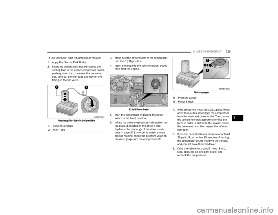
To use your Semi-Auto Kit, proceed as follows:
1. Apply the Electric Park Brake.
2. Insert the sealant cartridge containing the sealing fluid in the proper compressor holder,
pushing down hard. Unscrew the tire valve
cap, take out the filler tube and tighten the
fitting on the tire valve.
Attaching Filler Tube To Deflated Tire
3. Make sure the power switch of the compressor
is in the O (off) position.
4. Insert the plug into the vehicle’s power outlet, then start the engine.
12 Volt Power Outlet
5. Start the compressor by placing the power switch in the I (on) position.
6. Inflate the tire to the pressure indicated on the tire placard, located on the driver’s side
B-pillar or the rear edge of the driver’s side
door Ú page 273. In order to obtain a more
precise reading, check the pressure value on
pressure gauge with the compressor off.
Air Compressor
7. If the pressure is not at least 26.1 psi (1.8 bar) after 15 minutes, disengage the compressor
from the valve and power outlet. Then, move
the vehicle forwards approximately five tire
turns in order to distribute the sealant inside
the tire evenly, and then repeat the inflation
operation.
8. If you still cannot obtain a pressure of at least 26 psi (1.8 bar) within 15 minutes of turning
the compressor on, do not drive the vehicle,
and contact an authorized dealer.
9. Drive the vehicle for about 5 miles (8 km), stop, apply the electric park brake, and
recheck the tire pressure.
1 — Sealant Cartridge
2 — Filler Tube
5 — Pressure Gauge
6 — Power Switch
7
22_FD_OM_EN_USC_t.book Page 225
Page 228 of 312
226IN CASE OF EMERGENCY
10. If the pressure is less than 26 psi (1.8 bar), DO
NOT drive the vehicle, and see an authorized
dealer.
11. If a pressure value of at least 26 psi (1.8 bar) is detected, restore the correct pressure (with
engine running and electric park brake
applied), and drive immediately with great care
to an authorized dealer.
12. Apply the adhesive label from the sealant bottle where it can be easily seen by the driver
as a reminder that the tire has been treated
with a Semi-Auto Kit, as well as not to exceed
the speed restriction for the treated tire.
SEALANT CARTRIDGE REPLACEMENT
NOTE:Only use original cartridges, which can be
purchased at an authorized dealer.
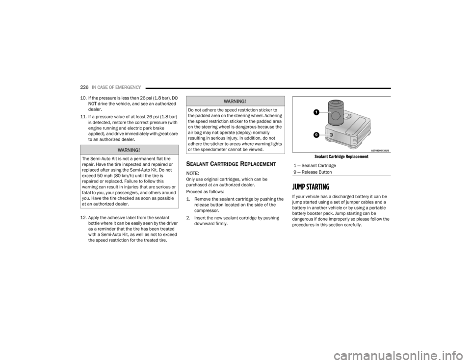
Proceed as follows:
1. Remove the sealant cartridge by pushing the release button located on the side of the
compressor.
2. Insert the new sealant cartridge by pushing downward firmly.
Sealant Cartridge Replacement
JUMP STARTING
If your vehicle has a discharged battery it can be
jump started using a set of jumper cables and a
battery in another vehicle or by using a portable
battery booster pack. Jump starting can be
dangerous if done improperly so please follow the
procedures in this section carefully.
WARNING!
The Semi-Auto Kit is not a permanent flat tire
repair. Have the tire inspected and repaired or
replaced after using the Semi-Auto Kit. Do not
exceed 50 mph (80 km/h) until the tire is
repaired or replaced. Failure to follow this
warning can result in injuries that are serious or
fatal to you, your passengers, and others around
you. Have the tire checked as soon as possible
at an authorized dealer.
WARNING!
Do not adhere the speed restriction sticker to
the padded area on the steering wheel. Adhering
the speed restriction sticker to the padded area
on the steering wheel is dangerous because the
air bag may not operate (deploy) normally
resulting in serious injury. In addition, do not
adhere the sticker to areas where warning lights
or the speedometer cannot be viewed.
1 — Sealant Cartridge
9 — Release Button
22_FD_OM_EN_USC_t.book Page 226
Page 237 of 312
235
SERVICING AND MAINTENANCE
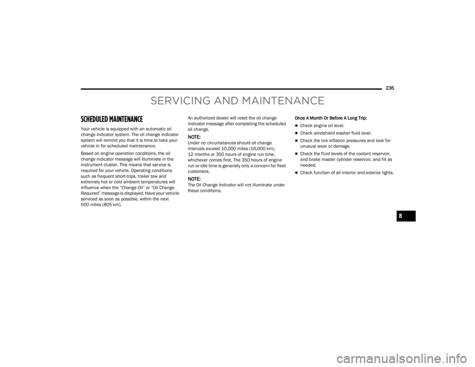
SCHEDULED MAINTENANCE
Your vehicle is equipped with an automatic oil
change indicator system. The oil change indicator
system will remind you that it is time to take your
vehicle in for scheduled maintenance.
Based on engine operation conditions, the oil
change indicator message will illuminate in the
instrument cluster. This means that service is
required for your vehicle. Operating conditions
such as frequent short-trips, trailer tow and
extremely hot or cold ambient temperatures will
influence when the “Change Oil” or “Oil Change
Required” message is displayed. Have your vehicle
serviced as soon as possible, within the next
500 miles (805 km).An authorized dealer will reset the oil change
indicator message after completing the scheduled
oil change.
NOTE:Under no circumstances should oil change
intervals exceed 10,000 miles (16,000 km),
12 months or 350 hours of engine run time,
whichever comes first. The 350 hours of engine
run or idle time is generally only a concern for fleet
customers.
NOTE:The Oil Change Indicator will not illuminate under
these conditions.
Once A Month Or Before A Long Trip:
Check engine oil level.
Check windshield washer fluid level.
Check the tire inflation pressures and look for
unusual wear or damage.
Check the fluid levels of the coolant reservoir,
and brake master cylinder reservoir, and fill as
needed.
Check function of all interior and exterior lights.
8
22_FD_OM_EN_USC_t.book Page 235
Page 238 of 312
236SERVICING AND MAINTENANCE
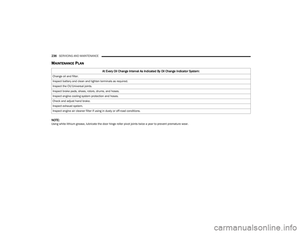
MAINTENANCE PLAN
NOTE:Using white lithium grease, lubricate the door hinge roller pivot joints twice a year to prevent premature wear.
At Every Oil Change Interval As Indicated By Oil Change Indicator System:
Change oil and filter.
Inspect battery and clean and tighten terminals as required.
Inspect the CV/Universal joints.
Inspect brake pads, shoes, rotors, drums, and hoses.
Inspect engine cooling system protection and hoses.
Check and adjust hand brake.
Inspect exhaust system.
Inspect engine air cleaner filter if using in dusty or off-road conditions.
22_FD_OM_EN_USC_t.book Page 236
Page 239 of 312
SERVICING AND MAINTENANCE237
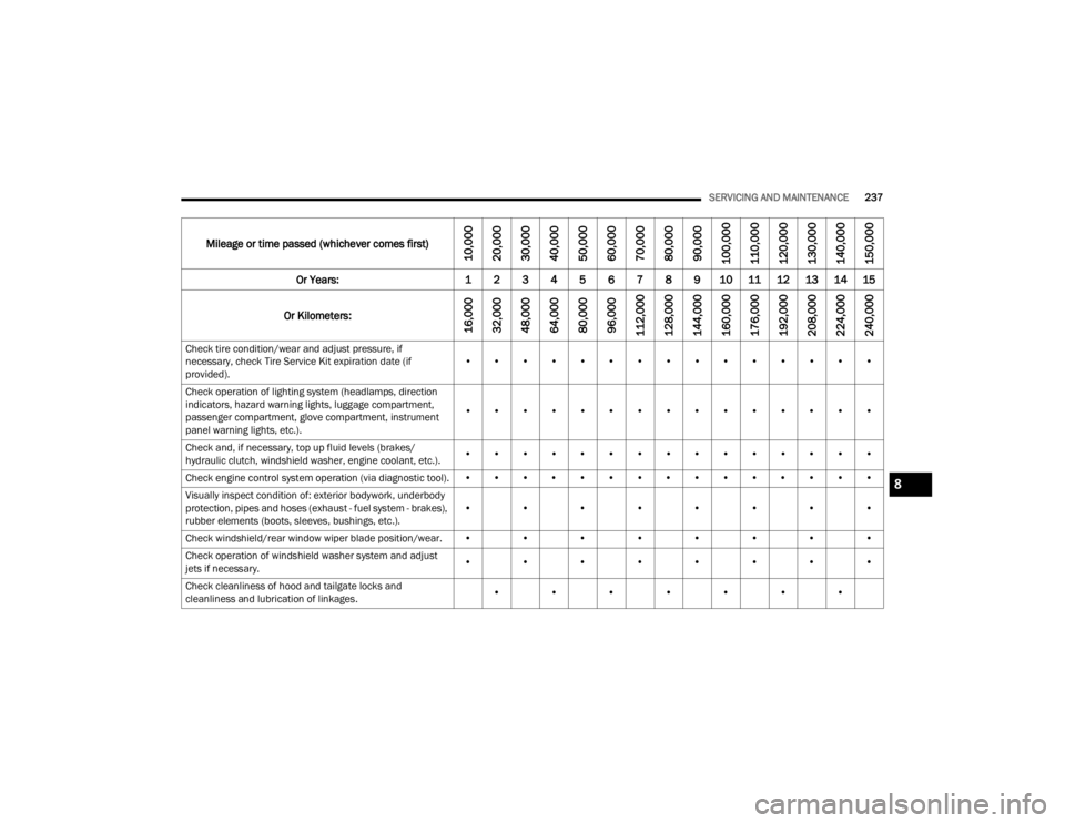
Mileage or time passed (whichever comes first)
10,000
20,000
30,000
40,000
50,000
60,000
70,000
80,000
90,000
100,000
110,000
120,000
130,000
140,000
150,000
Or Years: 1 2 3 4 5 6 7 8 9 10 11 12 13 14 15
Or Kilometers:
16,000
32,000
48,000
64,000
80,000
96,000
112,000
128,000
144,000
160,000
176,000
192,000
208,000
224,000
240,000
Check tire condition/wear and adjust pressure, if
necessary, check Tire Service Kit expiration date (if
provided). • • • • • • • • • • • • • • •
Check operation of lighting system (headlamps, direction
indicators, hazard warning lights, luggage compartment,
passenger compartment, glove compartment, instrument
panel warning lights, etc.). • • • • • • • • • • • • • • •
Check and, if necessary, top up fluid levels (brakes/
hydraulic clutch, windshield washer, engine coolant, etc.). • • • • • • • • • • • • • • •
Check engine control system operation (via diagnostic tool). • • • • • • • • • • • • • • •
Visually inspect condition of: exterior bodywork, underbody
protection, pipes and hoses (exhaust - fuel system - brakes),
rubber elements (boots, sleeves, bushings, etc.). • • • • • • • •
Check windshield/rear window wiper blade position/wear. • • • • • • • •
Check operation of windshield washer system and adjust
jets if necessary. • • • • • • • •
Check cleanliness of hood and tailgate locks and
cleanliness and lubrication of linkages. • • • • • • •
8
22_FD_OM_EN_USC_t.book Page 237
Page 240 of 312
238SERVICING AND MAINTENANCE
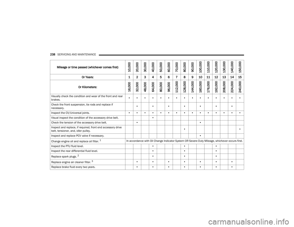
Visually check the condition and wear of the front and rear
brakes. • • • • • • • • • • • • • • •
Check the front suspension, tie rods and replace if
necessary. • • • • • • •
Inspect the CV/Universal joints. • • • • • • • • • • • • • • •
Visual inspect the condition of the accessory drive belt. •
Check the tension of the accessory drive belt. ••
Inspect and replace, if required, front end accessory drive
belt, tensioner, and, idler pulley. •
•
Inspect and replace PCV valve if necessary. •
Change engine oil and replace oil filter.
1In accordance with Oil Change Indicator System OR Severe Duty Mileage, whichever occurs first.
Inspect the PTU fluid level. •••
Inspect the rear differential fluid level. •••
Replace spark plugs.
2• ••
Replace engine air cleaner filter.
3• • • • • • •
Replace brake fluid every two years. • • • • • • •
Mileage or time passed (whichever comes first)
10,000
20,000
30,000
40,000
50,000
60,000
70,000
80,000
90,000
100,000
110,000
120,000
130,000
140,000
150,000
Or Years: 1 2 3 4 5 6 7 8 9 10 11 12 13 14 15
Or Kilometers:
16,000
32,000
48,000
64,000
80,000
96,000
112,000
128,000
144,000
160,000
176,000
192,000
208,000
224,000
240,000
22_FD_OM_EN_USC_t.book Page 238
Page 243 of 312
SERVICING AND MAINTENANCE241
CHECKING OIL LEVEL
To ensure proper engine lubrication, the engine oil
must be maintained at the correct level. Check the
oil level at regular intervals, such as every fuel
stop. The best time to check the engine oil level is
about five minutes after a fully warmed up engine
is shut off.
Checking the oil while the vehicle is on level ground
will improve the accuracy of the oil level readings.
NOTE:The dipstick is integral with the cap.
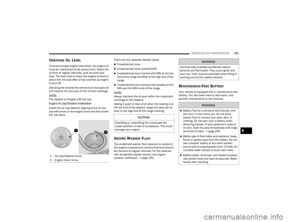
Engine Oil Cap/Dipstick Installation
Install the oil cap/dipstick aligning arrow on the
cap with arrow on the engine cover and then screw
the cap down. There are four possible dipstick types:
Crosshatched zone.
Crosshatched zone marked SAFE.
Crosshatched zone marked with MIN at the low
end of the range and MAX at the high end of the
range.
Crosshatched zone marked with dimples at the
MIN and the MAX ends of the range.
NOTE:Always maintain the oil level within the crosshatch
markings on the dipstick.
Adding 1 quart (1 liter) of oil when the reading is at
the low end of the dipstick range will raise the oil
level to the high end of the range marking.
ADDING WASHER FLUID
The windshield washer fluid reservoir is located in
the engine compartment, and the fluid level should
be checked at regular intervals. Fill the reservoir
with windshield washer solvent (not engine
coolant/ antifreeze) Ú
page 240.
MAINTENANCE-FREE BATTERY
Your vehicle is equipped with a maintenance-free
battery. You will never have to add water, and
periodic maintenance is not required.
1 — Oil Cap/Dipstick Arrow
2 — Engine Cover Arrow
CAUTION!
Overfilling or underfilling the crankcase will
cause aeration or loss of oil pressure. This could
damage your engine.
WARNING!
Commercially available windshield washer
solvents are flammable. They could ignite and
burn you. Care must be exercised when filling or
working around the washer solution.
WARNING!
Battery fluid is a corrosive acid solution and
can burn or even blind you. Do not allow
battery fluid to contact your eyes, skin, or
clothing. Do not lean over a battery when
attaching clamps. If acid splashes in eyes or
on skin, flush the area immediately with large
amounts of water Ú page 226.
Battery gas is flammable and explosive. Keep
flame or sparks away from the battery. Do not
use a booster battery or any other booster
source with an output greater than 12 Volts. Do
not allow cable clamps to touch each other.
Battery posts, terminals, and related accesso -
ries contain lead and lead compounds. Wash
hands after handling.
8
22_FD_OM_EN_USC_t.book Page 241