change time FIAT BRAVO 2013 2.G Owners Manual
[x] Cancel search | Manufacturer: FIAT, Model Year: 2013, Model line: BRAVO, Model: FIAT BRAVO 2013 2.GPages: 299, PDF Size: 5.86 MB
Page 2 of 299
We really know your car because we invented, designed and built it: we really know every single detail.
At Fiat Service authorised workshopsyou can find technicians directly trained by us,
offering quality and professionalism for all service operations.
Fiat workshops are always close to you for the regular servicing operations, season checks
and practical recommendations by our experts.
With Fiat Genuine Parts you keep the reliability, comfort and performance features
of your new car unchanged in time: that's why you bought it for.
Always ask for Genuine Parts for the components used on our cars; we recommend them because
they come from our steady commitment in research and development of highly innovative technologies.
For all these reasons: rely on Genuine Parts, because they are the only ones designed
by Fiat for your car.
SAFETY:
BRAKING SYSTEMENVIRONMENT: PARTICULATE FILTERS,
CLIMATE CONTROL MAINTENANCECOMFORT: SUSPENSION
AND WINDSCREEN WIPERS PERFORMANCE: SPARK PLUGS,
INJECTORS AND BATTERIESLINEACCESSORI
ROOF RACK BARS, WHEEL RIMS
WHY CHOOSING
GENUINE PARTS
BRAVO LUM GB:BRAVO UM GB 24-05-2012 14:30 Pagina 2
Page 27 of 299
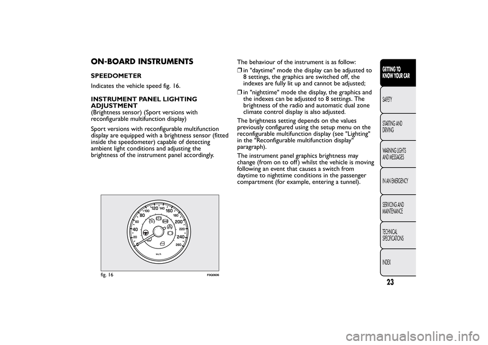
ON-BOARD INSTRUMENTSSPEEDOMETER
Indicates the vehicle speed fig. 16.
INSTRUMENT PANEL LIGHTING
ADJUSTMENT
(Brightness sensor) (Sport versions with
reconfigurable multifunction display)
Sport versions with reconfigurable multifunction
display are equipped with a brightness sensor (fitted
inside the speedometer) capable of detecting
ambient light conditions and adjusting the
brightness of the instrument panel accordingly.The behaviour of the instrument is as follow:
❒in "daytime" mode the display can be adjusted to
8 settings, the graphics are switched off, the
indexes are fully lit up and cannot be adjusted;
❒in "nighttime" mode the display, the graphics and
the indexes can be adjusted to 8 settings. The
brightness of the radio and automatic dual zone
climate control display is also adjusted.
The brightness setting depends on the values
previously configured using the setup menu on the
reconfigurable multifunction display (see "Lighting"
in the "Reconfigurable multifunction display"
paragraph).
The instrument panel graphics brightness may
change (from on to off ) whilst the vehicle is moving
following an event that causes a switch from
daytime to nighttime conditions in the passenger
compartment (for example, entering a tunnel).
fig. 16
F0Q0606
23GETTING TO
KNOW YOUR CARSAFETY
STARTING AND
DRIVING
WARNING LIGHTS
AND MESSAGES
IN AN EMERGENCY
SERVICING AND
MAINTENANCE
TECHNICAL
SPECIFICATIONS
INDEX
Page 33 of 299
SETUP MENU
The menu fig. 22 comprises a series of functions
arranged in a cycle which can be selected through
buttons
and
to access the different selection
and setting options (setup) given in the following
paragraphs. A submenu is provided for some
options ("Time adjustment" and "Unit of
measurement").
The setup menu can be activated by pressing the
MODE button briefly.
Single presses on buttons
or
will scroll through
the setup menu options. Operating modes are
different according to the characteristics of the
option selected.
If the Radionavigator system is installed, only the
following functions can be adjusted/set from the
instrument panel: "Lighting," “Speed beep” and
"Headlight sensor" (for versions/markets, where
provided), "Belt buzzer" and "Passenger airbag". The
other functions are shown on the Radionavigator
display. Set and adjustment them there.Selecting an option from the main menu without a
submenu:
❒briefly press button MODE to select the main
menu option that needs to be changed;
❒press buttons
or
(with single presses) to
select the new setting;
❒briefly press button MODE to store the new
setting and at the same time go back to the
previously selected menu option.
Selecting an option from the main menu with a
submenu:
❒briefly press the MODE button to display the
first submenu option;
❒press buttons
or
(with single presses) to
scroll through all the submenu options;
❒briefly press the MODE button to select the
displayed submenu option and to open the
relevant settings menu;
❒press buttons
or
(with single presses) to
select the new setting for this submenu option;
❒briefly press button MODE to store the new
setting and at the same time go back to the
previously selected submenu option.
29GETTING TO
KNOW YOUR CARSAFETY
STARTING AND
DRIVING
WARNING LIGHTS
AND MESSAGES
IN AN EMERGENCY
SERVICING AND
MAINTENANCE
TECHNICAL
SPECIFICATIONS
INDEX
Page 37 of 299
Note Buttons
and
activate different functions
according to the following situations:
❒within the menu, they allow you to scroll up and
down through the options;
❒during settings operations, they increase or
decrease values.
Note When opening one of the front doors, the
display will turn on and show for a few seconds the
time and the distance covered.GEAR SHIFT INDICATOR
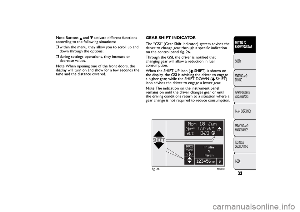
The “GSI” (Gear Shift Indicator) system advises the
driver to change gear through a specific indication
on the control panel fig. 26.
Through the GSI, the driver is notified that
changing gear will allow a reduction in fuel
consumption.
When the SHIFT UP icon (
SHIFT) is shown on
the display, the GSI is advising the driver to engage
a higher gear, while the SHIFT DOWN (
SHIFT)
icon advises the driver to engage a lower gear.
Note The indication on the instrument panel
remains on until the driver changes gear or until
the driving conditions return to a situation where a
gear change is not required to reduce consumption.
fig. 26
F0Q3242
33GETTING TO
KNOW YOUR CARSAFETY
STARTING AND
DRIVING
WARNING LIGHTS
AND MESSAGES
IN AN EMERGENCY
SERVICING AND
MAINTENANCE
TECHNICAL
SPECIFICATIONS
INDEX
Page 38 of 299
SETUP MENU
The menu fig. 27 comprises a series of functions
arranged in a cycle which can be selected through
buttons
and
to access the different selection
and setting options (setup) given in the following
paragraphs. A submenu is provided for some
options (Time adjustment and Unit of
measurement).
The setup menu can be activated by pressing the
MODE button briefly.
Single presses on buttons
or
will scroll through
the setup menu options. Operating modes are
different according to the characteristics of the
option selected.
If the Radionavigator system is installed, only the
following functions can be adjusted/set from the
instrument panel:
"Lighting," “Speed beep” and "Headlight sensor" (for
versions/markets, where provided), "Belt buzzer"
and "Passenger airbag". The other functions are
shown on the Radionavigator display. Set and
adjustment them there.Selecting an option from the main menu without a
submenu:
❒briefly press button MODE to select the main
menu option that needs to be changed;
❒press buttons
or
(with single presses) to
select the new setting;
❒briefly press button MODE to store the new
setting and at the same time go back to the
previously selected menu option.
Selecting an option from the main menu with a
submenu:
❒briefly press the MODE button to display the
first submenu option;
❒press buttons
or
(with single presses) to
scroll through all the submenu options;
❒briefly press the MODE button to select the
displayed submenu option and to open the
relevant settings menu;
❒press buttons
or
(with single presses) to
select the new setting for this submenu option;
❒briefly press button MODE to store the new
setting and at the same time go back to the
previously selected submenu option.
34GETTING TO
KNOW YOUR CAR
SAFETY
STARTING AND
DRIVING
WARNING LIGHTS
AND MESSAGES
IN AN EMERGENCY
SERVICING AND
MAINTENANCE
TECHNICAL
SPECIFICATIONS
INDEX
Page 42 of 299
Trip B data (Activating Trip B)
With this function is possible to turn the Trip B
display (trip meter) on and off.
For further information, see “Trip computer”
paragraph.
Proceed as follows to switch the function on and
off:
❒briefly press the MODE button: On or Off
flashes on the display (according to the previous
setting);
❒press
or
to make your choice;
❒briefly press the MODE button to return to the
menu screen or hold the button down to return
to the standard screen without memorising.
Time adjustment (Clock adjustment)
This function enables to set the clock through two
submenus: “Time” and “Format”.
To carry out the adjustment, proceed as follows:
❒briefly press the MODE button and two
submenus, "Time" and "Format", are displayed;
❒press the button
or
to switch between the
two submenus;
❒once you have selected the submenu to be
changed, press the button MODE briefly;
❒when you select “Time”, briefly pressing the
MODE button makes the hours flash on the
display;❒press the
or
button to make the adjustment;
❒briefly press the MODE button: “minutes” starts
flashing on the display;
❒press the buttonor
for setting.
Note The setting will increase or decrease by one
unit each time
or
is pressed. Hold down the
button to increase/decrease the setting rapidly and
automatically. Complete the setting by briefly
pressing the button when you approach the
required value.
❒if you enter the "Format" submenu, pressing the
MODE button briefly makes the display format
flash on the display;
❒press button
or
to select “24h” or “12h”.
When you have made the adjustment, briefly press
the MODE button to go back to the submenu
screen or hold the button down to go back to the
main menu screen without storing.
❒Hold down MODE button again to return to the
standard screen or to the main menu according
to where you are in the menu.
38GETTING TO
KNOW YOUR CAR
SAFETY
STARTING AND
DRIVING
WARNING LIGHTS
AND MESSAGES
IN AN EMERGENCY
SERVICING AND
MAINTENANCE
TECHNICAL
SPECIFICATIONS
INDEX
Page 76 of 299
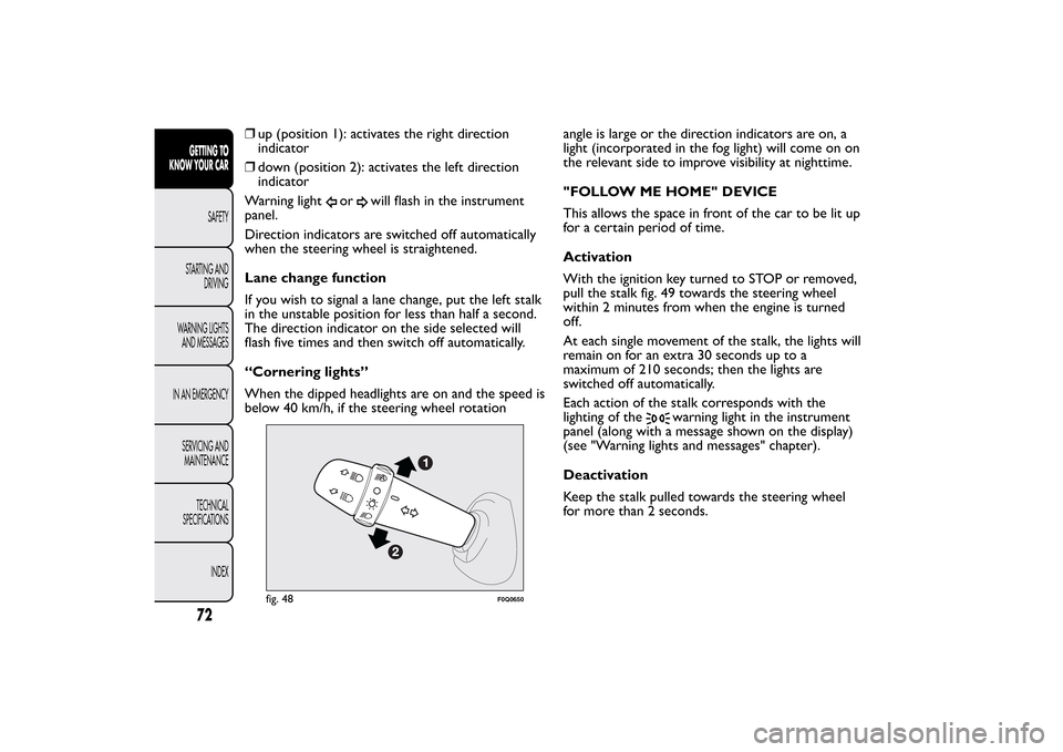
❒up (position 1): activates the right direction
indicator
❒down (position 2): activates the left direction
indicator
Warning light
or
will flash in the instrument
panel.
Direction indicators are switched off automatically
when the steering wheel is straightened.
Lane change function
If you wish to signal a lane change, put the left stalk
in the unstable position for less than half a second.
The direction indicator on the side selected will
flash five times and then switch off automatically.
“Cornering lights”
When the dipped headlights are on and the speed is
below 40 km/h, if the steering wheel rotationangle is large or the direction indicators are on, a
light (incorporated in the fog light) will come on on
the relevant side to improve visibility at nighttime.
"FOLLOW ME HOME" DEVICE
This allows the space in front of the car to be lit up
for a certain period of time.
Activation
With the ignition key turned to STOP or removed,
pull the stalk fig. 49 towards the steering wheel
within 2 minutes from when the engine is turned
off.
At each single movement of the stalk, the lights will
remain on for an extra 30 seconds up to a
maximum of 210 seconds; then the lights are
switched off automatically.
Each action of the stalk corresponds with the
lighting of the
warning light in the instrument
panel (along with a message shown on the display)
(see "Warning lights and messages" chapter).
Deactivation
Keep the stalk pulled towards the steering wheel
for more than 2 seconds.
fig. 48
F0Q0650
72GETTING TO
KNOW YOUR CAR
SAFETY
STARTING AND
DRIVING
WARNING LIGHTS
AND MESSAGES
IN AN EMERGENCY
SERVICING AND
MAINTENANCE
TECHNICAL
SPECIFICATIONS
INDEX
Page 109 of 299
HEADLIGHTSLIGHT BEAM DIRECTION
The correct direction of the headlights is essential
for the comfort and safety of the driver and other
road users. The headlights must be correctly
directed to ensure the best visibility. Contact a Fiat
Dealership to have the headlights checked and
adjusted.
IMPORTANT When the gas discharge (Xenon)
bulbs (for versions/markets, where provided) are
switched on, normally parabolas and light beam
move vertically for about 2 seconds until headlight
alignment has stabilised.
HEADLIGHT ALIGNMENT CORRECTOR
This device works with the ignition key in the
MAR-ON position and the dipped headlights on.
The car will tilt backwards when it is loaded, raising
the light beam. The beams must therefore be
realigned in this case.
Adjusting headlights alignment
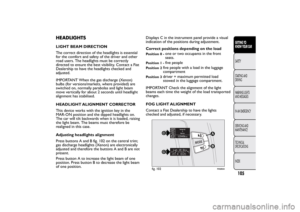
Press buttons A and B fig. 102 on the central trim;
gas discharge headlights (Xenon) are electronically
adjusted and therefore the buttons A and B are not
present.
Press button A to increase the light beam of one
position. Press button B to decrease the light beam
of one position.Displays C in the instrument panel provide a visual
indication of the positions during adjustment.
Correct positions depending on the load
Position 0 -
one or two occupants in the front
seats.
Position 1 -
five people
Position 2
five people with a load in the luggage
compartment
Position 3
driver + maximum permitted load
stowed in the luggage compartment.
IMPORTANT Check the alignment of the light
beams each time the weight of the load transported
changes.
FOG LIGHT ALIGNMENT
Contact a Fiat Dealership to have the lights
checked and adjusted, if necessary.
fig. 102
F0Q0644
105GETTING TO
KNOW YOUR CARSAFETY
STARTING AND
DRIVING
WARNING LIGHTS
AND MESSAGES
IN AN EMERGENCY
SERVICING AND
MAINTENANCE
TECHNICAL
SPECIFICATIONS
INDEX
Page 126 of 299
send the relative indications to the instrument
panel only after the vehicle has been in motion for a
short time.
Tyre pressure must be checked with tyres rested
and cold. Should it become necessary for whatever
reason to check pressure with warm tyres, do
not reduce pressure even though it is higher than
the prescribed value, but repeat the check when
tyres are cold (see "Wheels" in the "Technical data"
chapter).
The TPMS cannot indicate sudden tyre pressure
drops (for example when a tyre bursts). In this
case, stop the car, braking with caution and avoiding
abrupt steering.
Strong radio-frequency interference could inhibit
the correct operation of the TPMS. This condition
is indicated to the driver by the
warning light
or the symbol lighting up on the instrument panel
together with a message on the display. The
message will disappear automatically as soon as the
interference ceases to affect the system.
The TPMS requires the use of specific equipment.
Contact a Fiat Dealership to find out which
accessories are compatible with the system
(wheels, hub caps, etc.). Using other accessories
may hinder the normal operation of the system.
Given the valve unique specifications, only use
Fiat-approved sealers to repair the tyres. The use of
other sealers may affect the normal operation of
the system.If the vehicle is fitted with TPMS, when a tyre is
removed, it is advisable to replace the rubber
gasket for the valve as well as the ring nut fixing the
sensor. Have this operation performed at a Fiat
Dealership.
If the "punctured tyre" indication persists on the
instrument panel after the initial conditions have
been restored using the Fix&Go Automatic tyre
repair kit, contact a Fiat Dealership.
Changes in outside temperature may cause tyre
pressures to vary. The TPMS may temporarily
indicate insufficient pressure. In this case, check the
tyre pressure when cold and, if necessary, restore
the inflation values.
If the vehicle is fitted with TPMS, tyre and/or rims
fitting/removal operations require specific
precautions. To avoid damaging the sensors or
fitting them incorrectly, tyre and/or rims
fitting/removal operations should be carried out
only by specialists. Contact a Fiat Dealership.
122GETTING TO
KNOW YOUR CAR
SAFETY
STARTING AND
DRIVING
WARNING LIGHTS
AND MESSAGES
IN AN EMERGENCY
SERVICING AND
MAINTENANCE
TECHNICAL
SPECIFICATIONS
INDEX
Page 129 of 299
When reverse gear is released, the front and rear
sensors remain activated until a speed of around 15
km/h is exceeded to allow the parking manoeuvre
to be completed.
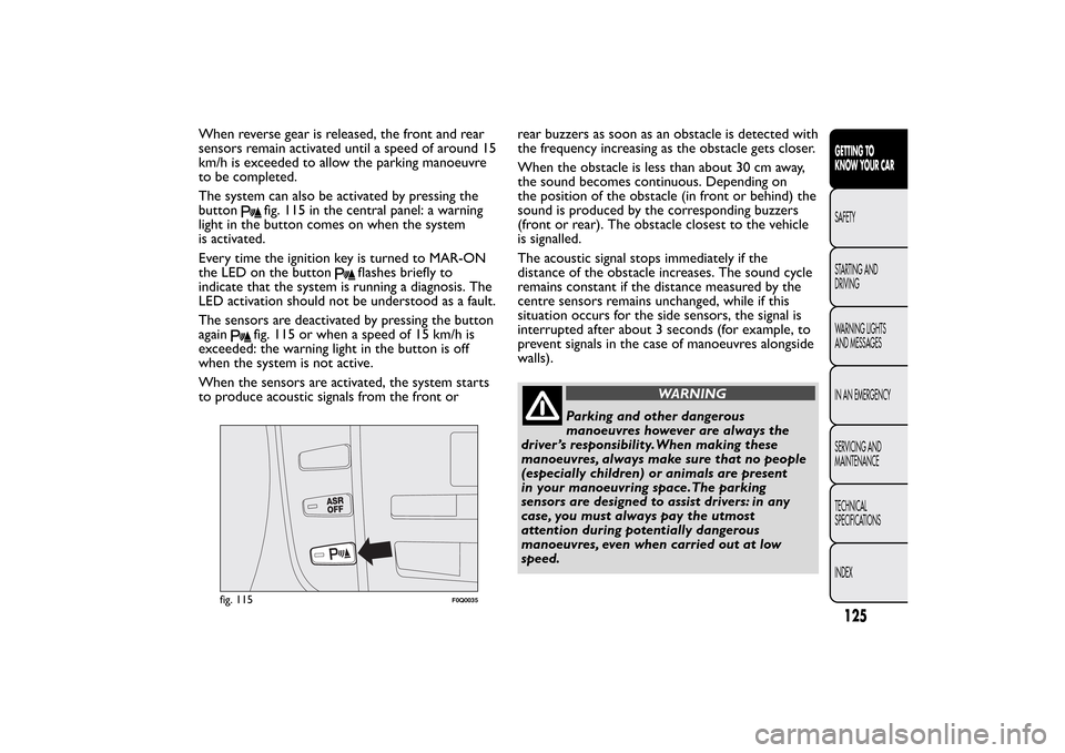
The system can also be activated by pressing the
button
fig. 115 in the central panel: a warning
light in the button comes on when the system
is activated.
Every time the ignition key is turned to MAR-ON
the LED on the button
flashes briefly to
indicate that the system is running a diagnosis. The
LED activation should not be understood as a fault.
The sensors are deactivated by pressing the button
again
fig. 115 or when a speed of 15 km/h is
exceeded: the warning light in the button is off
when the system is not active.
When the sensors are activated, the system starts
to produce acoustic signals from the front orrear buzzers as soon as an obstacle is detected with
the frequency increasing as the obstacle gets closer.
When the obstacle is less than about 30 cm away,
the sound becomes continuous. Depending on
the position of the obstacle (in front or behind) the
sound is produced by the corresponding buzzers
(front or rear). The obstacle closest to the vehicle
is signalled.
The acoustic signal stops immediately if the
distance of the obstacle increases. The sound cycle
remains constant if the distance measured by the
centre sensors remains unchanged, while if this
situation occurs for the side sensors, the signal is
interrupted after about 3 seconds (for example, to
prevent signals in the case of manoeuvres alongside
walls).
WARNING
Parking and other dangerous
manoeuvres however are always the
driver ’s responsibility.When making these
manoeuvres, always make sure that no people
(especially children) or animals are present
in your manoeuvring space.The parking
sensors are designed to assist drivers: in any
case, you must always pay the utmost
attention during potentially dangerous
manoeuvres, even when carried out at low
speed.
fig. 115
F0Q0035
125GETTING TO
KNOW YOUR CARSAFETY
STARTING AND
DRIVING
WARNING LIGHTS
AND MESSAGES
IN AN EMERGENCY
SERVICING AND
MAINTENANCE
TECHNICAL
SPECIFICATIONS
INDEX