sensor FIAT BRAVO 2014 2.G User Guide
[x] Cancel search | Manufacturer: FIAT, Model Year: 2014, Model line: BRAVO, Model: FIAT BRAVO 2014 2.GPages: 275, PDF Size: 3.95 MB
Page 105 of 275
If the vehicle is fitted with TPMS, when a tyre is
removed, it is advisable to replace the rubber gasket
for the valve as well as the ring nut fixing the sensor.
Have this operation performed at a Fiat Dealership.
If the punctured tyre indication persists on the
instrument panel after the initial conditions have
been restored using the tyre repair kit ("Fix&Go
Automatic"), contact a Fiat Dealership.
Changes in outside temperature may cause tyre
pressures to vary. The TPMS may temporarily
indicate insufficient pressure. In this case, check the
tyre pressure when cold and, if necessary, restore
the inflation values.
If the vehicle is fitted with TPMS, tyre and/or rims
fitting/removal operations require specific
precautions. To avoid damaging the sensors or fitting
them incorrectly, tyre and/or rims fitting/removal
operations should be carried out only by specialists.
Contact a Fiat Dealership.
The tyre repair kit ("Fix&Go Automatic")
provided with the car is compatible with
the TPMS sensors; using sealants not
equivalent with that in the original kit may
adversely affect its operation. If sealants not
equivalent with the original one are used, it
is recommended to have the TPMS sensors
checked by a qualified repair centre.
101GETTING TO
KNOW YOUR CARSAFETY
STARTING AND
DRIVING
WARNING LIGHTS
AND MESSAGES
IN AN EMERGENCY
SERVICING AND
MAINTENANCE
TECHNICAL
SPECIFICATIONS
INDEX
Page 106 of 275
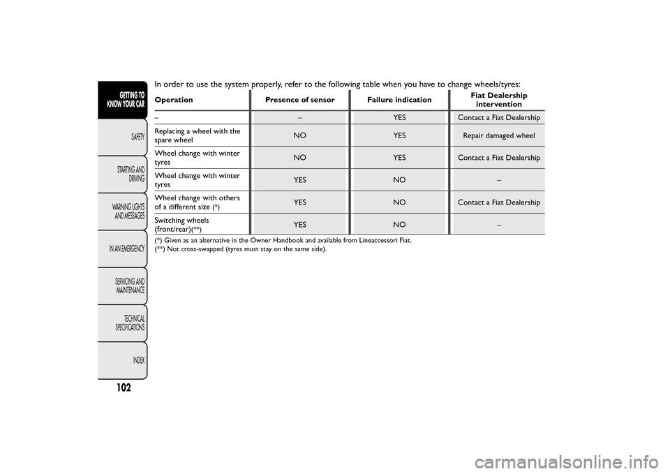
In order to use the system properly, refer to the following table when you have to change wheels/tyres:Operation Presence of sensor Failure indicationFiat Dealership
intervention
– – YES Contact a Fiat Dealership
Replacing a wheel with the
spare wheelNO YES Repair damaged wheel
Wheel change with winter
tyresNO YES Contact a Fiat Dealership
Wheel change with winter
tyresYES NO –
Wheel change with others
of a different size
(*)
YES NO Contact a Fiat Dealership
Switching wheels
(front/rear)
(**)
YES NO –
(*) Given as an alternative in the Owner Handbook and available from Lineaccessori Fiat.
(**) Not cross-swapped (tyres must stay on the same side).
102GETTING TO
KNOW YOUR CAR
SAFETY
STARTING AND
DRIVING
WARNING LIGHTS
AND MESSAGES
IN AN EMERGENCY
SERVICING AND
MAINTENANCE
TECHNICAL
SPECIFICATIONS
INDEX
Page 107 of 275
PARKING SENSORS(for versions/markets, where provided)
Parking sensors provide the driver with information
on the distance when approaching obstacles behind
the vehicle (versions with 4 rear sensors) or in
front of and behind the vehicle (versions with 4 front
and 4 rear sensors).
The system therefore provides a further aid during
parking manoeuvres because it allows the
identification of obstacles outside of the driver's field
of vision.
The driver is notified of the presence and distance of
the obstacle from the vehicle by an acoustic signal
which varies depending on the distance from the
obstacle (as the distance from the obstacle decreases
the frequency of the acoustic signal increases).
SENSORS
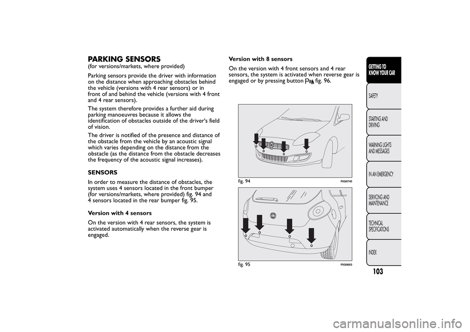
In order to measure the distance of obstacles, the
system uses 4 sensors located in the front bumper
(for versions/markets, where provided) fig. 94 and
4 sensors located in the rear bumper fig. 95.
Version with 4 sensors
On the version with 4 rear sensors, the system is
activated automatically when the reverse gear is
engaged.Version with 8 sensors
On the version with 4 front sensors and 4 rear
sensors, the system is activated when reverse gear is
engaged or by pressing button
fig. 96.
fig. 94
F0Q0745
fig. 95
F0Q0603
103GETTING TO
KNOW YOUR CARSAFETY
STARTING AND
DRIVING
WARNING LIGHTS
AND MESSAGES
IN AN EMERGENCY
SERVICING AND
MAINTENANCE
TECHNICAL
SPECIFICATIONS
INDEX
Page 108 of 275
When reverse gear is released, the front and rear
sensors remain activated until a speed of around 15
km/h is exceeded to allow the parking manoeuvre to
be completed.
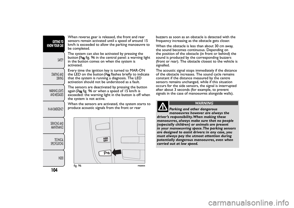
The system can also be activated by pressing the
button
fig. 96 in the central panel: a warning light
in the button comes on when the system is
activated.
Every time the ignition key is turned to MAR-ON
the LED on the button
flashes briefly to indicate
that the system is running a diagnosis. The LED
activation should not be understood as a fault.
The sensors are deactivated by pressing the button
again
fig. 96 or when a speed of 15 km/h is
exceeded: the warning light in the button is off when
the system is not active.
When the sensors are activated, the system starts to
produce acoustic signals from the front or rearbuzzers as soon as an obstacle is detected with the
frequency increasing as the obstacle gets closer.
When the obstacle is less than about 30 cm away,
the sound becomes continuous. Depending on
the position of the obstacle (in front or behind) the
sound is produced by the corresponding buzzers
(front or rear). The obstacle closest to the vehicle is
signalled.
The acoustic signal stops immediately if the distance
of the obstacle increases. The sound cycle remains
constant if the distance measured by the centre
sensors remains unchanged, while if this situation
occurs for the side sensors, the signal is interrupted
after about 3 seconds (for example, to prevent
signals in the case of manoeuvres alongside walls).
WARNING
Parking and other dangerous
manoeuvres however are always the
driver ’s responsibility.When making these
manoeuvres, always make sure that no people
(especially children) or animals are present
in your manoeuvring space.The parking sensors
are designed to assist drivers: in any case, you
must always pay the utmost attention during
potentially dangerous manoeuvres, even when
carried out at low speed.
fig. 96
F0Q0035
104GETTING TO
KNOW YOUR CAR
SAFETY
STARTING AND
DRIVING
WARNING LIGHTS
AND MESSAGES
IN AN EMERGENCY
SERVICING AND
MAINTENANCE
TECHNICAL
SPECIFICATIONS
INDEX
Page 109 of 275
ACOUSTIC SIGNAL
The information concerning the presence and
distance of an obstacle from the vehicle is
transmitted by means of acoustic signals from
buzzers installed in the passenger compartment:
❒in the versions with 4 rear sensors, a buzzer in the
front dashboard area warns of the presence of rear
obstacles;
❒in the versions with 8 sensors (4 front and 4 rear
sensors), a front buzzer warns of the presence of
obstacles at the front and a buzzer located at
the rear warns of the presence of obstacles at the
rear. This notifies the driver of the direction
(front/rear) of the obstacles.
When reverse gear is engaged an intermittent
acoustic signal is automatically activated.
The acoustic signal:
❒increases as the distance between the car and the
obstacle decreases;
❒becomes continuous when the distance between
the car and the obstacle is less than 30 cm and
stops immediately if the distance increases;
❒remains constant if the distance remains
unchanged; if this situation concerns the side
sensors, the buzzer will stop after about 3 seconds
to avoid, for example, warning indications in the
event of manoeuvres along walls.
WARNING
For correct operation, sensors must
always be clean from mud, dirt , snow or
ice. Be careful not to scratch or damage the
sensors while cleaning them. Avoid using dry,
rough or hard cloths.The sensors should be
washed using clean water with the addition of
car shampoo if necessary. In washing stations,
clean sensors quickly keeping the vapour
jet/high pressure washing nozzles at 10 cm at
least from the sensors.
WARNING
Only have the bumpers repainted or any
retouches to the paintwork in the area
of the sensors carried out by a Fiat Dealership.
Incorrect paint application could affect the
operation of the parking sensors.
105GETTING TO
KNOW YOUR CARSAFETY
STARTING AND
DRIVING
WARNING LIGHTS
AND MESSAGES
IN AN EMERGENCY
SERVICING AND
MAINTENANCE
TECHNICAL
SPECIFICATIONS
INDEX
Page 110 of 275
SENSOR OPERATING RANGE
The sensors allow the system to check the front part
(version with 8 sensors) and rear part of the vehicle.
Their position covers the middle and side areas of
the front and rear of the vehicle.
If an obstacle is located in a middle area, it is
detected when the distance is less than about 0.9 m
(front) and 1.40 m (rear).
If the obstacle is located at the side, it is detected at
distances of less than 0.6 m.
OPERATION WITH TRAILER
The operation of the sensors is automatically
deactivated when the trailer's electric cable plug is
inserted in the car's tow hook socket.
The sensors are automatically enabled again when
the trailer's cable plug is removed.
IMPORTANT If you wish to leave the tow hook
fitted when there is no trailer, it is advisable to
contact a Fiat Dealership to have the system updated
because the tow hook could be detected as an
obstacle by the central sensors.FAILURE INDICATIONS
Any failures in the parking sensor system are
signalled, when reverse gear is engaged, by the
warning light
in the instrument panel lighting up
or by the symbol
together with a message in the
display (see "Warning lights and messages" chapter).
GENERAL WARNINGS
During parking manoeuvres, pay the utmost
attention to any obstacles that could be located
above or below the sensors.
Under certain circumstances close objects located in
front of or behind the car may not be detected and
could therefore cause damage to the car or be
damaged themselves.
The following conditions may influence the
performance of the parking sensor system:
❒Reduced sensor sensitivity and a reduction in the
parking assistance system performance could be
due to the presence on the surface of the sensor
of: ice, snow, mud, thick paint.
❒The sensors may detect a non-existent obstacle
(echo interference) due to mechanical
interference, for example when washing the car, in
rain (strong wind), hail.
❒The signals sent by the sensors can also be altered
by the presence of ultrasonic systems (e.g.
pneumatic brake systems or pneumatic drills) near
the vehicle.
106GETTING TO
KNOW YOUR CAR
SAFETY
STARTING AND
DRIVING
WARNING LIGHTS
AND MESSAGES
IN AN EMERGENCY
SERVICING AND
MAINTENANCE
TECHNICAL
SPECIFICATIONS
INDEX
Page 111 of 275
❒The performance of the parking assistance system
may also be affected by the position of the
sensors. For example, if the geometry is altered
(as a result of wear of the shock absorbers,
suspension), the tyres are changed, the vehicle is
too heavily laden or specific tuning is carried
out that lowers the vehicle.
❒The detection of obstacles at the top part of the
car may not be guaranteed because the system
detects obstacles that could cause an impact with
the car in the bottom part.
AT THE FILLING STATIONMOTORI DIESEL - Operation at low
temperatures
If the outside temperature is very low, diesel
thickens due to the formation of paraffin clots with
consequent defective operation of the fuel supply
system.
In order to avoid these problems, different types of
diesel are distributed according to the season:
summer type, winter type and arctic type
(cold/mountain areas). If refuelling with diesel fuel
whose specifications are not suitable for the current
temperature, it is advisable to mix TUTELA DIESEL
ART additive in the proportions shown on the
container. Pour the additive into the tank before the
diesel fuel.
When using or parking the car for a long time in the
mountains or cold areas, it is advisable to refuel
using locally available diesel. In this case, it is also
advisable to keep the tank over 50% full.
107GETTING TO
KNOW YOUR CARSAFETY
STARTING AND
DRIVING
WARNING LIGHTS
AND MESSAGES
IN AN EMERGENCY
SERVICING AND
MAINTENANCE
TECHNICAL
SPECIFICATIONS
INDEX
Page 155 of 275
INCOMPLETE DOOR LOCKING
(red)
The warning light switches on when one or more
doors are not completely shut. An acoustic signal is
activated with the doors open and the car moving.GENERIC FAILURE INDICATION
(amber)
Fuel cut-off inertia switch tripped
The warning light comes on when the inertial fuel
cut-off switch is triggered. The display shows the
dedicated message.
Engine oil pressure sensor failure
The warning light comes on when the engine oil
pressure sensor is faulty.
Dusk sensor failure
This warning light comes on when a dusk sensor
fault is detected. The display shows the dedicated
message.
Preset speed limit exceeded
(for Arab countries only)
The warning light switches on when the vehicle
speed exceeds 120 km/h.Rain sensor failure
The warning light switches on when a rain sensor
fault is detected. The display shows the dedicated
message.
Parking sensor failure
(for versions/markets, where provided)
The warning light turns on when failure is detected in
the parking sensors.
Tyre pressure monitoring system failure
(for versions/markets, where provided)
The warning light turns on when a failure is detected
in the TPMS (for versions/markets where provided).
Should one or more wheels without a sensor be
fitted, the instrument panel warning light will come
on and stay on until the initial conditions are
restored. The display shows the dedicated message.
NoteIf one of the above mentioned failures occurs,
contact a Fiat Dealership as soon as possible.
151GETTING TO KNOW
YOUR CAR
SAFETY
STARTING AND
DRIVINGWARNING LIGHTS
AND MESSAGESIN AN EMERGENCY
SERVICING AND
MAINTENANCE
TECHNICAL
SPECIFICATIONS
INDEX
Page 197 of 275
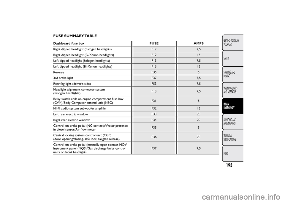
FUSE SUMMARY TABLEDashboard fuse box FUSE AMPS
Right dipped headlight (halogen headlights) F12 7,5
Right dipped headlight (Bi-Xenon headlights) F12 15
Left dipped headlight (halogen headlights) F13 7,5
Left dipped headlight (Bi-Xenon headlights) F13 15
Reverse F35 5
3rd brake light F37 7,5
Rear fog light (driver's side) F53 7,5
Headlight alignment corrector system
(halogen headlights)F13 7,5
Relay switch coils on engine compartment fuse box
(CVM)/Body Computer control unit (NBC)F31 5
HI-FI audio system subwoofer amplifier F32 15
Left rear electric window F33 20
Right rear electric window F34 20
Control on brake pedal (NC contact)/Water presence
in diesel sensor/Air flow meterF35 5
Central locking system control unit (CGP)
(door opening/closing, safe lock, tailgate release)F36 20
Control on brake pedal (normally open contact NO)/
Instrument panel (NQS)/Gas discharge bulbs control
units on front headlightsF37 7,5
193GETTING TO KNOW
YOUR CAR
SAFETY
STARTING AND
DRIVING
WARNING LIGHTS
AND MESSAGESIN AN
EMERGENCYSERVICING AND
MAINTENANCE
TECHNICAL
SPECIFICATIONS
INDEX
Page 198 of 275
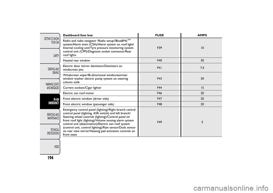
Dashboard fuse box FUSE AMPS
Radio and radio navigator /Radio setup//Blue&Me
TM
system/Alarm siren (CSA)/Alarm system on roof light/
Internal cooling unit/Tyre pressure monitoring system
control unit (CPP)/Diagnosis socket connector/Rear
roof lightsF39 10
Heated rear window F40 30
Electric door mirror demisters/Demisters on
windscreen jetsF41 7,5
Windscreen wiper/Bi-directional windscreen/rear
window washer electric pump system on steering
column stalkF43 30
Current sockets/Cigar lighter F44 15
Electric sun roof motor F46 20
Front electric window (driver side) F47 20
Front electric window (passenger side) F48 20
Emergency control panel (lighting)/Right branch central
control panel (lighting, ASR switch) and left branch/
Steering wheel controls (lighting)/Control panel on
front roof light (lighting)/Volume sensing alarm system
control unit (deactivation)/Electric sun roof system
(control unit, control lighting)/Rain sensor/Dusk sensor
on rear view mirror/Heating pad activation controls on
front seatsF49 5
194GETTING TO KNOW
YOUR CAR
SAFETY
STARTING AND
DRIVING
WARNING LIGHTS
AND MESSAGES
IN AN
EMERGENCY
SERVICING AND
MAINTENANCE
TECHNICAL
SPECIFICATIONS
INDEX