tow FIAT DOBLO COMBI 2017 2.G Owners Manual
[x] Cancel search | Manufacturer: FIAT, Model Year: 2017, Model line: DOBLO COMBI, Model: FIAT DOBLO COMBI 2017 2.GPages: 300, PDF Size: 24.91 MB
Page 20 of 300
WARNING
1)Used batteries are harmful to the
environment. You can dispose of them
either in the correct containers as specified
by law or by taking them to a Fiat
Dealership, which will deal with their
disposal.
IGNITION DEVICE
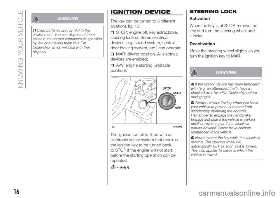
The key can be turned to 3 different
positions fig. 10:
STOP: engine off, key extractable,
steering locked. Some electrical
devices (e.g. sound system, central
door locking system, etc.) can operate;
MAR: driving position. All electrical
devices are enabled;
AVV: engine starting (unstable
position).
The ignition switch is fitted with an
electronic safety system that requires
the ignition key to be turned back
to STOP if the engine will not start,
before the starting operation can be
repeated.
4) 5) 6) 7)
STEERING LOCK
Activation
When the key is at STOP, remove the
key and turn the steering wheel until
it locks.
Deactivation
Move the steering wheel slightly as you
turn the ignition key to MAR.
WARNING
4)If the ignition device has been tampered
with (e.g. an attempted theft), have it
checked over by a Fiat Dealership before
driving again.
5)Always remove the key when you leave
your vehicle to prevent someone from
accidentally operating the controls.
Remember to engage the handbrake.
Engage first gear if the vehicle is parked
uphill or reverse gear if the vehicle is
parked downhill. Never leave children
unattended in the vehicle.
6)Never extract the key while the vehicle is
moving. The steering wheel will
automatically lock as soon as it is turned.
This also applies to cases in which the
vehicle is towed.
10F0V0006
16
KNOWING YOUR VEHICLE
Page 23 of 300
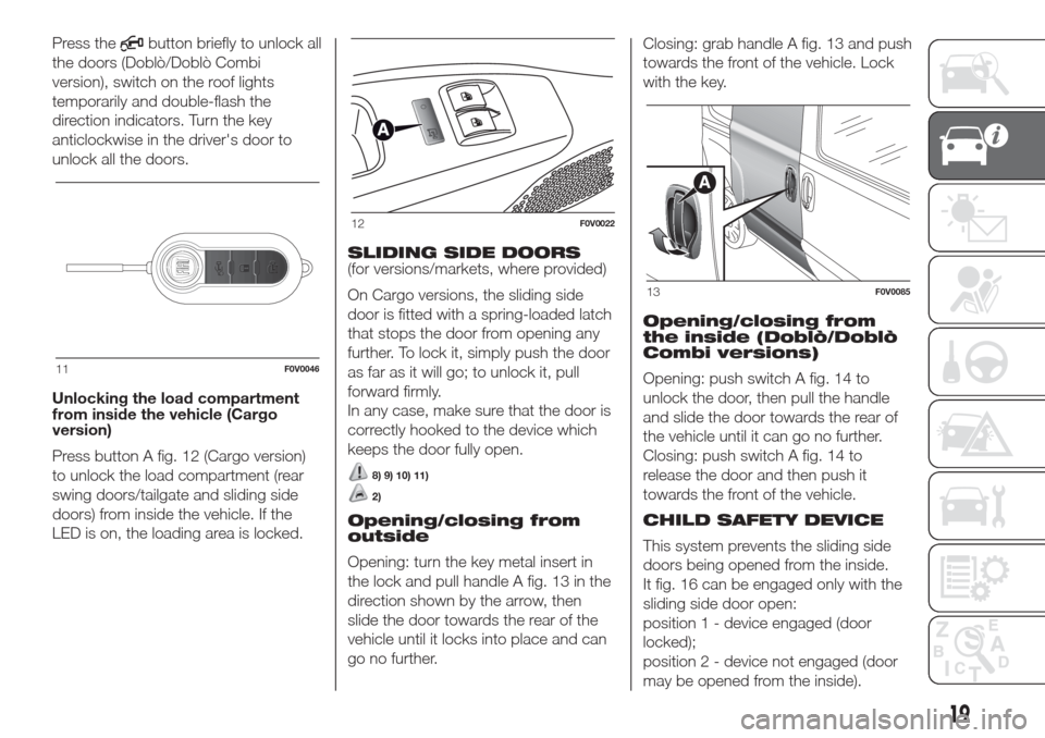
Press thebutton briefly to unlock all
the doors (Doblò/Doblò Combi
version), switch on the roof lights
temporarily and double-flash the
direction indicators. Turn the key
anticlockwise in the driver's door to
unlock all the doors.
Unlocking the load compartment
from inside the vehicle (Cargo
version)
Press button A fig. 12 (Cargo version)
to unlock the load compartment (rear
swing doors/tailgate and sliding side
doors) from inside the vehicle. If the
LED is on, the loading area is locked.SLIDING SIDE DOORS
(for versions/markets, where provided)
On Cargo versions, the sliding side
door is fitted with a spring-loaded latch
that stops the door from opening any
further. To lock it, simply push the door
as far as it will go; to unlock it, pull
forward firmly.
In any case, make sure that the door is
correctly hooked to the device which
keeps the door fully open.
8) 9) 10) 11)
2)
Opening/closing from
outside
Opening: turn the key metal insert in
the lock and pull handle A fig. 13 in the
direction shown by the arrow, then
slide the door towards the rear of the
vehicle until it locks into place and can
go no further.Closing: grab handle A fig. 13 and push
towards the front of the vehicle. Lock
with the key.
Opening/closing from
the inside (Doblò/Doblò
Combi versions)
Opening: push switch A fig. 14 to
unlock the door, then pull the handle
and slide the door towards the rear of
the vehicle until it can go no further.
Closing: push switch A fig. 14 to
release the door and then push it
towards the front of the vehicle.
CHILD SAFETY DEVICE
This system prevents the sliding side
doors being opened from the inside.
It fig. 16 can be engaged only with the
sliding side door open:
position 1 - device engaged (door
locked);
position 2 - device not engaged (door
may be opened from the inside).
11F0V0046
12F0V0022
13F0V0085
19
Page 30 of 300
REMOVING 3RD ROW
SEATS
Proceed as follows:
remove the rear seat head restraints;
remove the rolling curtain from its
housing;
move the seat belt to the side,
making sure that it is fully extended and
not twisted;
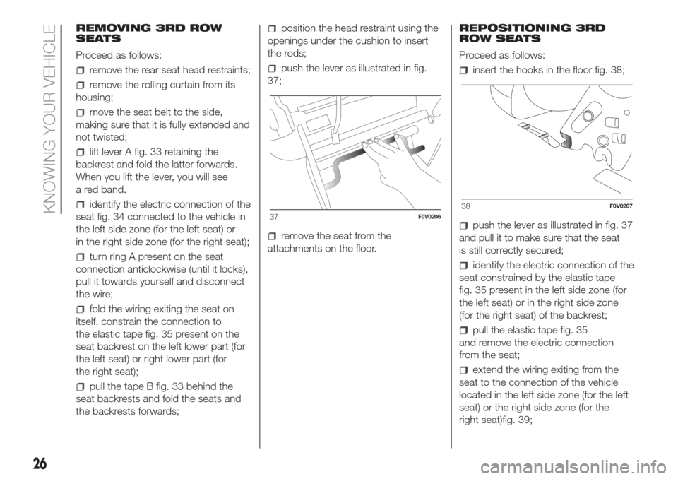
lift lever A fig. 33 retaining the
backrest and fold the latter forwards.
When you lift the lever, you will see
a red band.
identify the electric connection of the
seat fig. 34 connected to the vehicle in
the left side zone (for the left seat) or
in the right side zone (for the right seat);
turn ring A present on the seat
connection anticlockwise (until it locks),
pull it towards yourself and disconnect
the wire;
fold the wiring exiting the seat on
itself, constrain the connection to
the elastic tape fig. 35 present on the
seat backrest on the left lower part (for
the left seat) or right lower part (for
the right seat);
pull the tape B fig. 33 behind the
seat backrests and fold the seats and
the backrests forwards;
position the head restraint using the
openings under the cushion to insert
the rods;
push the lever as illustrated in fig.
37;
remove the seat from the
attachments on the floor.REPOSITIONING 3RD
ROW SEATS
Proceed as follows:
insert the hooks in the floor fig. 38;
push the lever as illustrated in fig. 37
and pull it to make sure that the seat
is still correctly secured;
identify the electric connection of the
seat constrained by the elastic tape
fig. 35 present in the left side zone (for
the left seat) or in the right side zone
(for the right seat) of the backrest;
pull the elastic tape fig. 35
and remove the electric connection
from the seat;
extend the wiring exiting from the
seat to the connection of the vehicle
located in the left side zone (for the left
seat) or the right side zone (for the
right seat)fig. 39;
37F0V020638F0V0207
26
KNOWING YOUR VEHICLE
Page 35 of 300
WARNING
22)All adjustments must only be carried
out with the vehicle stationary and the
engine off. Head restraints must be
adjusted so that the head, rather than the
neck, rests on them. Only in this case
can they protect your head correctly.
23)To make the best use of the head
restraint's protective action, adjust the
backrest so that your torso is upright and
keep your head as close as possible to the
head restraint.
STEERING WHEEL
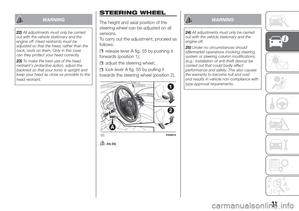
The height and axial position of the
steering wheel can be adjusted on all
versions.
To carry out the adjustment, proceed as
follows:
release lever A fig. 55 by pushing it
forwards (position 1);
adjust the steering wheel;
lock lever A fig. 55 by pulling it
towards the steering wheel (position 2).
24) 25)
WARNING
24)All adjustments must only be carried
out with the vehicle stationary and the
engine off.
25)Under no circumstances should
aftermarket operations involving steering
system or steering column modifications
(e.g.: installation of anti-theft device) be
carried out that could badly affect
performance and safety. This also causes
the warranty to become null and void
and results in vehicle non-compliance with
type-approval requirements.
55F0V0014
31
Page 38 of 300
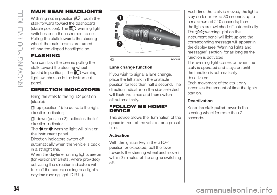
MAIN BEAM HEADLIGHTS
With ring nut in position
, push the
stalk forward toward the dashboard
(stable position). The
warning light
switches on in the instrument panel.
Pulling the stalk towards the steering
wheel, the main beams are turned
off and the dipped headlights on.
FLASHING
You can flash the beams pulling the
stalk toward the steering wheel
(unstable position). The
warning
light switches on in the instrument
panel.
DIRECTION INDICATORS
Bring the stalk to the fig. 62 position
(stable):
up (position 1): to activate the right
direction indicator;
down (position 2): activates the left
direction indicator.
The
orwarning light will blink on
the instrument panel.
Direction indicators switch off
automatically when the vehicle is back
in a straight line.
When the daytime running lights are on
(for versions/markets, where provided)
activating the direction indicators will
turn off the corresponding headlight’s
daytime running light (D.R.L.).Lane change function
If you wish to signal a lane change,
place the left stalk in the unstable
position for less than half a second. The
direction indicator on the side selected
will flash five times and then switch
off automatically.
"FOLLOW ME HOME"
DEVICE
This device allows the illumination of the
space in front of the vehicle for a preset
time.
Activation
With the ignition key in the STOP
position or extracted, pull the lever
towards the steering wheel and move it
within 2 minutes of the engine switching
off.Each time the stalk is moved, the lights
stay on for an extra 30 seconds up to
a maximum of 210 seconds; then
the lights are switched off automatically.
The
warning light on the
instrument panel will light up and the
corresponding message will appear in
the display (see “Warning lights and
messages” section) for as long as the
function is activated.
The warning light comes on when the
stalk is operated and stays on until
the function is automatically
deactivated.
Each movement of the stalk only
increases the amount of time the lights
stay on.
Deactivation
Keep the stalk pulled towards the
steering wheel for more than 2
seconds.
62F0V0516
34
KNOWING YOUR VEHICLE
Page 43 of 300
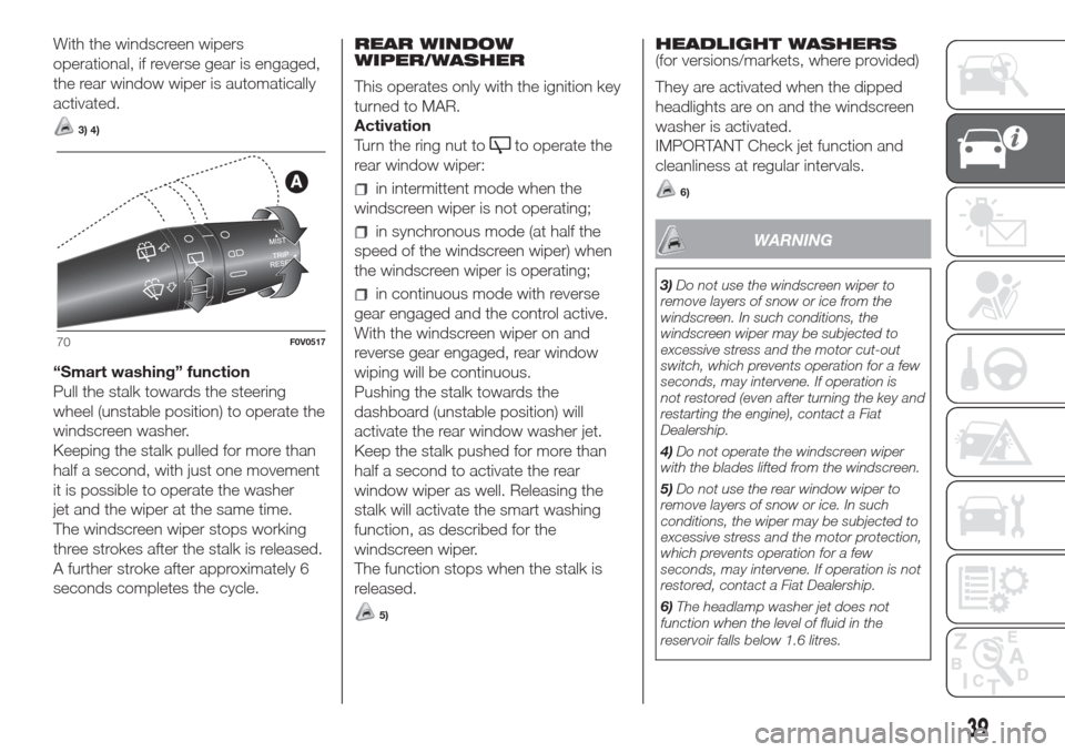
With the windscreen wipers
operational, if reverse gear is engaged,
the rear window wiper is automatically
activated.
3) 4)
“Smart washing” function
Pull the stalk towards the steering
wheel (unstable position) to operate the
windscreen washer.
Keeping the stalk pulled for more than
half a second, with just one movement
it is possible to operate the washer
jet and the wiper at the same time.
The windscreen wiper stops working
three strokes after the stalk is released.
A further stroke after approximately 6
seconds completes the cycle.REAR WINDOW
WIPER/WASHER
This operates only with the ignition key
turned to MAR.
Activation
Turn the ring nut to
to operate the
rear window wiper:
in intermittent mode when the
windscreen wiper is not operating;
in synchronous mode (at half the
speed of the windscreen wiper) when
the windscreen wiper is operating;
in continuous mode with reverse
gear engaged and the control active.
With the windscreen wiper on and
reverse gear engaged, rear window
wiping will be continuous.
Pushing the stalk towards the
dashboard (unstable position) will
activate the rear window washer jet.
Keep the stalk pushed for more than
half a second to activate the rear
window wiper as well. Releasing the
stalk will activate the smart washing
function, as described for the
windscreen wiper.
The function stops when the stalk is
released.
5)
HEADLIGHT WASHERS
(for versions/markets, where provided)
They are activated when the dipped
headlights are on and the windscreen
washer is activated.
IMPORTANT Check jet function and
cleanliness at regular intervals.
6)
WARNING
3)Do not use the windscreen wiper to
remove layers of snow or ice from the
windscreen. In such conditions, the
windscreen wiper may be subjected to
excessive stress and the motor cut-out
switch, which prevents operation for a few
seconds, may intervene. If operation is
not restored (even after turning the key and
restarting the engine), contact a Fiat
Dealership.
4)Do not operate the windscreen wiper
with the blades lifted from the windscreen.
5)Do not use the rear window wiper to
remove layers of snow or ice. In such
conditions, the wiper may be subjected to
excessive stress and the motor protection,
which prevents operation for a few
seconds, may intervene. If operation is not
restored, contact a Fiat Dealership.
6)The headlamp washer jet does not
function when the level of fluid in the
reservoir falls below 1.6 litres.
70F0V0517
39
Page 47 of 300
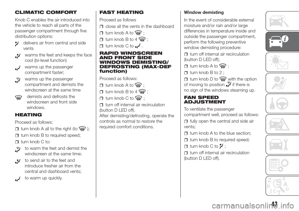
CLIMATIC COMFORT
Knob C enables the air introduced into
the vehicle to reach all parts of the
passenger compartment through five
distribution options:
delivers air from central and side
vents
warms the feet and keeps the face
cool (bi-level function)
warms up the passenger
compartment faster;
warms up the passenger
compartment and demists the
windscreen at the same time
demists and defrosts the
windscreen and front side
windows.
HEATING
Proceed as follows:
turn knob A all to the right (to);
turn knob B to required speed;
turn knob C to:
to warm the feet and demist the
windscreen at the same time;
to send air to the feet and
introduce fresher air from the
central and dashboard vents;
to warm up quickly.FAST HEATING
Proceed as follows
close all the vents in the dashboard
turn knob A to;
turn knob B to 4;
turn knob C to.
RAPID WINDSCREEN
AND FRONT SIDE
WINDOWS DEMISTING/
DEFROSTING (MAX-DEF
function)
Proceed as follows:
turn knob A to;
turn knob B to 4;
turn knob C to;
turn off internal air recirculation
(button D LED off).
After demisting/defrosting, operate the
controls as normal to restore the
required comfort conditions.Window demisting
In the event of considerable external
moisture and/or rain and/or large
differences in temperature inside and
outside the passenger compartment,
perform the following preventive
window demisting procedure:
turn off internal air recirculation
(button D LED off);
turn knob A to;
turnknobBto2;
turn knob D towith the option
of moving to position
if there is
no sign of the windows steaming up.
FAN SPEED
ADJUSTMENT
To ventilate the passenger
compartment well, proceed as follows:
fully open the central and side air
vents;
turn knob A to the blue section;
turn knob B to required speed;
turn knob C to;
turn off internal air recirculation
(button D LED off).
43
Page 69 of 300
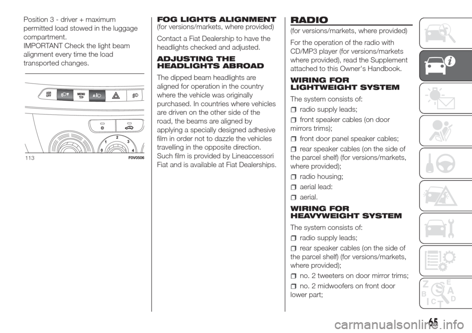
Position 3 - driver + maximum
permitted load stowed in the luggage
compartment.
IMPORTANT Check the light beam
alignment every time the load
transported changes.FOG LIGHTS ALIGNMENT
(for versions/markets, where provided)
Contact a Fiat Dealership to have the
headlights checked and adjusted.
ADJUSTING THE
HEADLIGHTS ABROAD
The dipped beam headlights are
aligned for operation in the country
where the vehicle was originally
purchased. In countries where vehicles
are driven on the other side of the
road, the beams are aligned by
applying a specially designed adhesive
film in order not to dazzle the vehicles
travelling in the opposite direction.
Such film is provided by Lineaccessori
Fiat and is available at Fiat Dealerships.RADIO
(for versions/markets, where provided)
For the operation of the radio with
CD/MP3 player (for versions/markets
where provided), read the Supplement
attached to this Owner's Handbook.
WIRING FOR
LIGHTWEIGHT SYSTEM
The system consists of:
radio supply leads;
front speaker cables (on door
mirrors trims);
front door panel speaker cables;
rear speaker cables (on the side of
the parcel shelf) (for versions/markets,
where provided);
radio housing;
aerial lead:
aerial.
WIRING FOR
HEAVYWEIGHT SYSTEM
The system consists of:
radio supply leads;
rear speaker cables (on the side of
the parcel shelf) (for versions/markets,
where provided);
no. 2 tweeters on door mirror trims;
no. 2 midwoofers on front door
lower part;
113F0V0506
65
Page 84 of 300
TRIP COMPUTER
IN BRIEF
The Trip computer is used to display
information on vehicle operation
when the ignition key is turned to
MAR. This function allows you to
define two separate trips, called "Trip
A" and "Trip B", for monitoring the
"complete mission" (journey) of
the vehicle in a reciprocally
independent manner. Both functions
can be reset (reset means start of
a new journey).
"Trip A" can be used to display the
values relating to:
Outside Temperature
Range
Distance travelled A
Average consumption A
Instantaneous consumption
Average speed A
Trip time A (driving time)
Reset Trip A
"Trip B", available on multifunction
display only, is used to display
the values relating to:
Distance travelled B
Average consumption B
Average speed B
Trip time B (driving time)
Trip B reset
11)
Values displayed
Outside temperature (for versions/
markets, where provided)
Indicates the temperature outside the
vehicle passenger compartment.
Range (for versions/markets, where
provided)
This indicates the distance that can still
be travelled with the fuel in the tank,
assuming that driving style remains
unvaried. The display will show the
reading '-----' when the following
events take place:
range is lower than 50 km (or
corresponding figure in mi)
vehicle is left parked with the engine
running for a long time
IMPORTANT The range can be affected
by several factors: driving style (see
“Driving style” in the “Starting and
driving” section), type of route
(motorway, towns and cities, mountain
roads, etc.), conditions of use (load,
tyre pressures, etc.). Trip planning must
therefore take the above into account.Distance travelled
This value shows the distance travelled
from the start of the new journey.
Average consumption (for versions/
markets, where provided)
This value shows the approximate
average fuel consumption from the start
of the new journey.
Instant consumption (for versions/
markets where provided)
This value shows the fuel consumption.
The value is constantly updated. The
display will show "----" if the car is
parked with the engine running.
Average speed
This value shows the car's average
speed based on the overall time
elapsed since the start of the new
journey.
80
KNOWING THE INSTRUMENT PANEL
Page 91 of 300
Warning lights on
panelWhat it means What to do
redLOW ENGINE OIL PRESSURE
When the key is turned to MAR, the digital warning light switches on, but it should
switch off as soon as the engine is started.
The warning light switches on constantly together with the message in the display
when the system detects that the engine oil pressure is insufficient.
12)
DECAYED ENGINE OIL
(MultiJet versions with DPF only)
The warning light starts to flash together with a message on the display (for
versions/markets, where provided) when the system detects that the engine oil
has deteriorated.
If the warning light flashes, this does not mean that the vehicle is faulty, but simply
informs the driver that it is now necessary to change the engine oil as a result of
regular vehicle use. If the oil is not changed, warning light
will also come on
and engine operation is limited to 3000 rpm when a second threshold is reached.
If the oil is still not changed, when a third deterioration threshold is reached, the
engine is limited to 1500 rpm to avoid damage.Contact a Fiat Dealership as
soon as possible.
50) 51)
Remember that the
deterioration of the engine oil
is accelerated by:
– mainly town use of the
vehicle which makes the DPF
regeneration process more
frequent
– use of the vehicle for short
trips, preventing the engine
from reaching operating
temperature
– repeated interruption of the
regeneration process,
signalled by the DPF warning
light coming on.
redLOW ENGINE OIL LEVEL
When turning the ignition key to MAR, the warning light turns on but it should go
off after a few seconds.
This warning light appears on the panel when the engine oil level falls below the
minimum recommended value.
On certain versions a dedicated message is displayed.Restore the correct engine oil
level (see “Checking fluid
levels” in the "Maintenance
and care" section).
87