Multi function display FIAT DUCATO 2008 3.G Owners Manual
[x] Cancel search | Manufacturer: FIAT, Model Year: 2008, Model line: DUCATO, Model: FIAT DUCATO 2008 3.GPages: 282, PDF Size: 4.55 MB
Page 5 of 282
4
SAFETY
DEVICES
CORRECT USE
OF THE
VEHICLE
WARNING
LIGHTS AND
MESSAGES
IN AN
EMERGENCY
VEHICLE
MAINTENANCE
TECHNICAL
SPECIFICATIONS
INDEX
DASHBOARD
AND CONTROLSDASHBOARD (LEFT HAND DRIVE VERSION) ......... 5
DASHBOARD (RIGHT HAND DRIVE VERSION) ...... 6
SYMBOLS ............................................................................... 7
THE FIAT CODE SYSTEM.................................................. 7
THE KEYS .............................................................................. 8
ELECTRONIC ALARM........................................................ 13
IGNITION DEVICE.............................................................. 15
INSTRUMENT PANEL (LEFT HAND DRIVE VERSION) 16
INSTRUMENT PANEL (RIGHT HAND DRIVE VERSION) 17
INSTRUMENTS..................................................................... 18
DIGITAL DISPLAY ............................................................... 21
MULTIFUNCTION DISPLAY ............................................ 26
TRIP COMPUTER ................................................................ 35
FRONT SEATS ..................................................................... 37
HEAD RESTRAINTS............................................................. 43
STEERING WHEEL .............................................................. 44
REARVIEW MIRRORS......................................................... 45
HEATING AND VENTILATION...................................... 47
MANUAL CLIMATE CONTROL SYSTEM .................... 51
AUTOMATIC CLIMATE CONTROL SYSTEM ............. 55
SUPPLEMENTARY HEATER ............................................. 65
SELF-STANDING SUPPLEMENTARY HEATER............ 66
SUPPLEMENTARY REAR HEATER.................................. 72SUPPLEMENTARY REAR AIR CONDITIONER........... 73
EXTERNAL LIGHTS............................................................. 74
WINDOW WASHING....................................................... 77
CRUISE CONTROL ............................................................ 79
CEILING LIGHTS ................................................................. 81
CONTROLS .......................................................................... 82
POWER SUPPLY AND FUEL CUT-OFF SWITCH ...... 84
INTERIOR FITTINGS........................................................... 85
MULTIMETER......................................................................... 91
SPEED BLOCK....................................................................... 92
DOORS .................................................................................. 92
POWER WINDOWS/WINDOW WINDERS .............. 97
BONNET................................................................................. 98
ROOF RACK/SKI RACK .................................................... 100
HEADLIGHTS........................................................................ 101
ABS SYSTEM ......................................................................... 102
ESP SYSTEM .......................................................................... 103
EOBD SYSTEM ..................................................................... 106
PARKING SENSORS ........................................................... 107
SOUND SYSTEM.................................................................. 108
ACCESSORIES PURCHASED BY THE OWNER .......... 109
AT THE FILLING STATION ............................................. 110
PROTECTING THE ENVIRONMENT............................. 112
DIESEL PARTICULATE FILTER (DPF) ............................. 112
DD D
A A
S S
H H
B B
O O
A A
R R
D D
A A
N N
D D
C C
O O
N N
T T
R R
O O
L L
S S
Page 6 of 282
5
SAFETY
DEVICES
CORRECT USE
OF THE
VEHICLE
WARNING
LIGHTS AND
MESSAGES
IN AN
EMERGENCY
VEHICLE
MAINTENANCE
TECHNICAL
SPECIFICATIONS
INDEX
DASHBOARD
AND CONTROLS
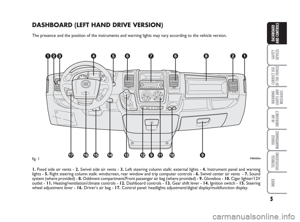
DASHBOARD (LEFT HAND DRIVE VERSION)
The presence and the position of the instruments and warning lights may vary according to the vehicle version.
1.Fixed side air vents - 2.Swivel side air vents - 3.Left steering column stalk: external lights - 4.Instrument panel and warning
lights - 5.Right steering column stalk: windscreen, rear window and trip computer controls - 6.Swivel center air vents - 7.Sound
system (where provided) - 8.Oddment compartment/Front passenger air bag (where provided) - 9.Glovebox - 10.Cigar lighter/12V
outlet - 11.Heating/ventilation/climate controls - 12.Dashboard controls - 13.Gear shift lever - 14.Ignition switch - 15. Steering
wheel adjustment lever - 16.Driver’s air bag - 17.Control panel: headlights adjustment/digital display/multifunction display.
F0N0320mfig. 1
Page 7 of 282
6
SAFETY
DEVICES
CORRECT USE
OF THE
VEHICLE
WARNING
LIGHTS AND
MESSAGES
IN AN
EMERGENCY
VEHICLE
MAINTENANCE
TECHNICAL
SPECIFICATIONS
INDEX
DASHBOARD
AND CONTROLS
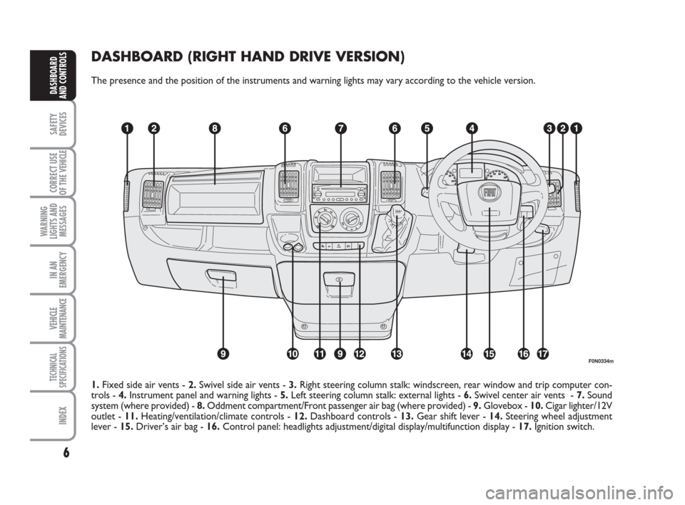
DASHBOARD (RIGHT HAND DRIVE VERSION)
The presence and the position of the instruments and warning lights may vary according to the vehicle version.
F0N0334m
1.Fixed side air vents - 2.Swivel side air vents - 3.Right steering column stalk: windscreen, rear window and trip computer con-
trols - 4.Instrument panel and warning lights - 5.Left steering column stalk: external lights - 6.Swivel center air vents - 7.Sound
system (where provided) - 8.Oddment compartment/Front passenger air bag (where provided) - 9.Glovebox - 10.Cigar lighter/12V
outlet - 11.Heating/ventilation/climate controls - 12.Dashboard controls - 13.Gear shift lever - 14. Steering wheel adjustment
lever - 15.Driver’s air bag - 16.Control panel: headlights adjustment/digital display/multifunction display - 17.Ignition switch.
Page 17 of 282
16
SAFETY
DEVICES
CORRECT USE
OF THE
VEHICLE
WARNING
LIGHTS AND
MESSAGES
IN AN
EMERGENCY
VEHICLE
MAINTENANCE
TECHNICAL
SPECIFICATIONS
INDEX
DASHBOARD
AND CONTROLS
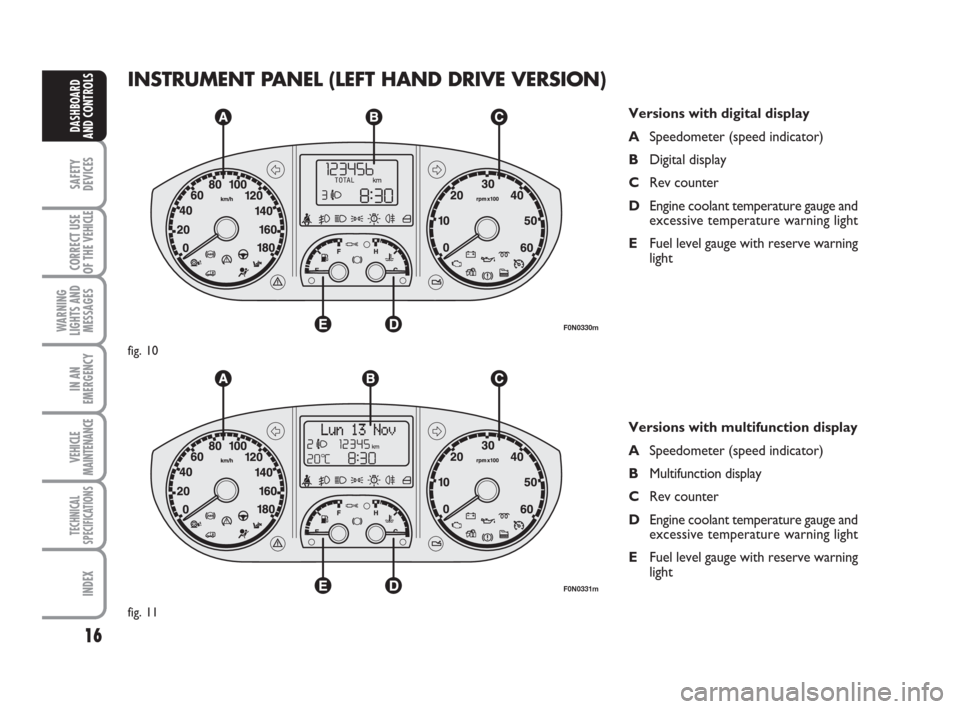
INSTRUMENT PANEL (LEFT HAND DRIVE VERSION)
Versions with digital display
ASpeedometer (speed indicator)
BDigital display
CRev counter
DEngine coolant temperature gauge and
excessive temperature warning light
EFuel level gauge with reserve warning
light
Versions with multifunction display
ASpeedometer (speed indicator)
BMultifunction display
CRev counter
DEngine coolant temperature gauge and
excessive temperature warning light
EFuel level gauge with reserve warning
light
F0N0330m
fig. 10
F0N0331m
fig. 11
Page 18 of 282
17
SAFETY
DEVICES
CORRECT USE
OF THE
VEHICLE
WARNING
LIGHTS AND
MESSAGES
IN AN
EMERGENCY
VEHICLE
MAINTENANCE
TECHNICAL
SPECIFICATIONS
INDEX
DASHBOARD
AND CONTROLS
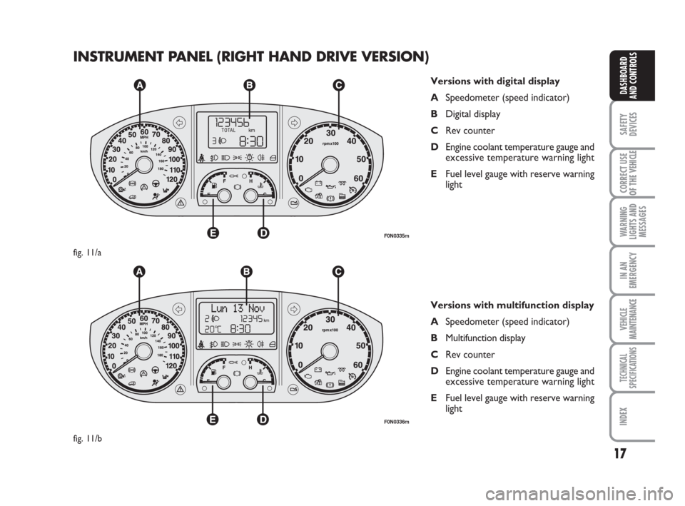
INSTRUMENT PANEL (RIGHT HAND DRIVE VERSION)
F0N0335m
fig. 11/a
F0N0336m
fig. 11/b
Versions with digital display
ASpeedometer (speed indicator)
BDigital display
CRev counter
DEngine coolant temperature gauge and
excessive temperature warning light
EFuel level gauge with reserve warning
light
Versions with multifunction display
ASpeedometer (speed indicator)
BMultifunction display
CRev counter
DEngine coolant temperature gauge and
excessive temperature warning light
EFuel level gauge with reserve warning
light
Page 20 of 282
19
SAFETY
DEVICES
CORRECT USE
OF THE
VEHICLE
WARNING
LIGHTS AND
MESSAGES
IN AN
EMERGENCY
VEHICLE
MAINTENANCE
TECHNICAL
SPECIFICATIONS
INDEX
DASHBOARD
AND CONTROLS
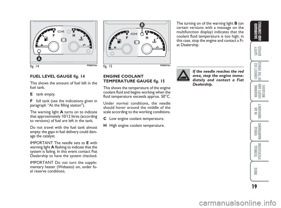
FUEL LEVEL GAUGE fig. 14
This shows the amount of fuel left in the
fuel tank.
Etank empty.
Ffull tank (see the indications given in
paragraph “At the filling station").
The warning light Aturns on to indicate
that approximately 10/12 litres (according
to versions) of fuel are left in the tank.
Do not travel with the fuel tank almost
empty: the gaps in fuel delivery could dam-
age the catalyst.
IMPORTANT The needle sets to Ewith
warning light Aflashing to indicate that the
system is failing. In this event contact Fiat
Dealership to have the system checked.
IMPORTANT Do not turn the supple-
mentary heater (Webasto) on, under fu-
el reserve conditions.ENGINE COOLANT
TEMPERATURE GAUGE fig. 15
This shows the temperature of the engine
coolant fluid and begins working when the
fluid temperature exceeds approx. 50°C.
Under normal conditions, the needle
should hover around the middle of the
scale according to the working conditions.
CLow engine coolant temperature.
HHigh engine coolant temperature.The turning on of the warning light B(on
certain versions with a message on the
multifunction display) indicates that the
coolant fluid temperature is too high; in
this case, stop the engine and contact a Fi-
at Dealership.
fig. 14F0N0014mfig. 15F0N0015m
If the needle reaches the red
area, stop the engine imme-
diately and contact a Fiat
Dealership.
Page 21 of 282
20
SAFETY
DEVICES
CORRECT USE
OF THE
VEHICLE
WARNING
LIGHTS AND
MESSAGES
IN AN
EMERGENCY
VEHICLE
MAINTENANCE
TECHNICAL
SPECIFICATIONS
INDEX
DASHBOARD
AND CONTROLS
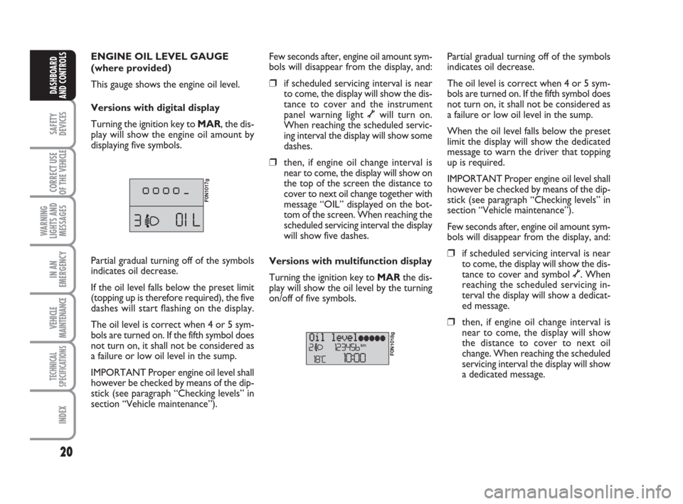
ENGINE OIL LEVEL GAUGE
(where provided)
This gauge shows the engine oil level.
Versions with digital display
Turning the ignition key to MAR, the dis-
play will show the engine oil amount by
displaying five symbols.
F0N1017g
Few seconds after, engine oil amount sym-
bols will disappear from the display, and:
❒if scheduled servicing interval is near
to come, the display will show the dis-
tance to cover and the instrument
panel warning light õwill turn on.
When reaching the scheduled servic-
ing interval the display will show some
dashes.
❒then, if engine oil change interval is
near to come, the display will show on
the top of the screen the distance to
cover to next oil change together with
message “OIL” displayed on the bot-
tom of the screen. When reaching the
scheduled servicing interval the display
will show five dashes.
Versions with multifunction display
Turning the ignition key to MARthe dis-
play will show the oil level by the turning
on/off of five symbols.
F0N1018g
Partial gradual turning off of the symbols
indicates oil decrease.
The oil level is correct when 4 or 5 sym-
bols are turned on. If the fifth symbol does
not turn on, it shall not be considered as
a failure or low oil level in the sump.
When the oil level falls below the preset
limit the display will show the dedicated
message to warn the driver that topping
up is required.
IMPORTANT Proper engine oil level shall
however be checked by means of the dip-
stick (see paragraph “Checking levels” in
section “Vehicle maintenance”).
Few seconds after, engine oil amount sym-
bols will disappear from the display, and:
❒if scheduled servicing interval is near
to come, the display will show the dis-
tance to cover and symbol õ. When
reaching the scheduled servicing in-
terval the display will show a dedicat-
ed message.
❒then, if engine oil change interval is
near to come, the display will show
the distance to cover to next oil
change. When reaching the scheduled
servicing interval the display will show
a dedicated message. Partial gradual turning off of the symbols
indicates oil decrease.
If the oil level falls below the preset limit
(topping up is therefore required), the five
dashes will start flashing on the display.
The oil level is correct when 4 or 5 sym-
bols are turned on. If the fifth symbol does
not turn on, it shall not be considered as
a failure or low oil level in the sump.
IMPORTANT Proper engine oil level shall
however be checked by means of the dip-
stick (see paragraph “Checking levels” in
section “Vehicle maintenance”).
Page 27 of 282
26
SAFETY
DEVICES
CORRECT USE
OF THE
VEHICLE
WARNING
LIGHTS AND
MESSAGES
IN AN
EMERGENCY
VEHICLE
MAINTENANCE
TECHNICAL
SPECIFICATIONS
INDEX
DASHBOARD
AND CONTROLS
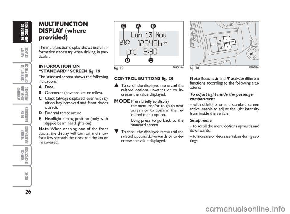
CONTROL BUTTONS fig. 20
▲To scroll the displayed menu and the
related options upwards or to in-
crease the value displayed.
MODEPress briefly to display
the menu and/or to go to next
screen or to confirm the re-
quired menu option.
Long press to go back to the
standard screen.
▼To scroll the displayed menu and the
related options downwards or to de-
crease the value displayed.
MULTIFUNCTION
DISPLAY (where
provided)
The multifunction display shows useful in-
formation necessary when driving, in par-
ticular:
INFORMATION ON
“STANDARD” SCREEN fig. 19
The standard screen shows the following
indications:
ADate.
BOdometer (covered km or miles).
CClock (always displayed, even with ig-
nition key removed and front doors
closed).
DExternal temperature.
EHeadlight aiming position (only with
dipped beam headlights on).
NoteWhen opening one of the front
doors, the display will turn on and show
for a few seconds the clock and the km or
mi covered.
fig. 19F0N0018m
NoteButtons ▲and ▼activate different
functions according to the following situ-
ations:
To adjust light inside the passenger
compartment
– with sidelights on and standard screen
active, enable to adjust the light intensity
from inside the vehicle
Setup menu
– to scroll the menu options upwards and
downwards;
– to increase or decrease values during set-
tings.
fig. 20F0N0017m
Page 36 of 282
35
SAFETY
DEVICES
CORRECT USE
OF THE
VEHICLE
WARNING
LIGHTS AND
MESSAGES
IN AN
EMERGENCY
VEHICLE
MAINTENANCE
TECHNICAL
SPECIFICATIONS
INDEX
DASHBOARD
AND CONTROLS
TRIP COMPUTER
General features
The “Trip computer” displays information
(with ignition key at MAR), relating to the
operating status of the vehicle. This func-
tion comprises two separate and inde-
pendent trips: “Trip A” and “Trip B” con-
cerning the “complete mission” of the ve-
hicle (journey).
Both functions are resettable (reset - start
of new mission).
“Trip A” shall be used to display the fig-
ures relating to:
– External temperature
– Range
– Trip distance
– Average consumption
– Instant consumption
– Average speed
– Travel time (driving time).“Trip B”, available on multifunction display
only, shall be used to display the figures
relating to:
– Trip distance B
– Average consumption B
– Average speed B
– Travel time B (driving time).
Note“Trip B” function can be excluded
(see paragraph “Trip B On/Off”). “Range”
and “Instant consumption” cannot be re-
set.
Values displayed
External temperature
It indicates the external temperature of
the driver compartment.
Range
This value shows the distance in km (or
mi) that the vehicle can still cover before
needing fuel, assuming that driving condi-
tions are kept unvaried. The display will
show “----” in the following cases:
– value lower than 50 km (or 30 mi)
– vehicle left parked with engine running
for long.
Trip distance
This value shows the distance covered
from the start of the new mission. Exit Menu
This is the last function that closes the cir-
cular setting cycle listed in the initial menu
screen.
Briefly press button MODEto go back to
the standard screen without storing set-
tings.
Press button ▼to return to the first menu
option (Speed Beep).
Page 94 of 282
93
SAFETY
DEVICES
CORRECT USE
OF THE
VEHICLE
WARNING
LIGHTS AND
MESSAGES
IN AN
EMERGENCY
VEHICLE
MAINTENANCE
TECHNICAL
SPECIFICATIONS
INDEX
DASHBOARD
AND CONTROLS
flashing. Turn the metal insert counter-
clockwise into the driver’s door lock
fig. 109to unlock all the doors.
With the battery disconnected, access to
the vehicle will only be possible by un-
locking the driver’s door using the me-
chanical lock.
Door locking/unlocking from
the inside
Press button A-fig. 110to lock and press
button Bto unlock the doors. Block/re-
lease actions are carried out centrally
(front and rear). When doors are locked
the button led Ais on and pressing the
button Bwill obtain central unlocking of
the doors and turning off of the led. When
doors are unlocked, the button led is off
and pressing the button will obtain central
locking of the doors. Door locking is ac-
tivated only if all the doors are perfectly
closed.
fig. 109F0N0059mfig. 110F0N0047m
fig. 111F0N0132m
Pulling the internal door handle of one of the
rear doors will unlock the relevant door.
Lacking power (blown fuse, battery discon-
nected, etc.) it is however possible to lock
the doors manually.
After exceeding 20 km/h speed, doors will
be locked automatically if the set up menu
function has been selected (see paragraph
“Multifunction display” in this section).
LOAD COMPARTMENT KEY
fig. 111
Lock activation is indicated by the led on
the key.
The led turns on in the following cases:
❒after each door lock command gener-
ated by the key itself or by key Øon
the dashboard;
❒upon instrument panel activation;
❒upon opening one of the front doors;
❒when the doors are locked at 20 km/h
(if this is activated from the menu);
Deactivation takes place upon opening
one of the load compartment doors or
upon a door release request (load com-
partment or centralised) or upon a release
request via the remote control/door pawl. After locking doors by:
❒remote control;
❒door revolving plug;
it will not be possible to unlock the doors
by pressing button
A-fig. 110.
IMPORTANT With central locking active
pulling the opening lever of one of the front
doors will cause central locking deactivation.