low beam FIAT DUCATO 2008 3.G Owners Manual
[x] Cancel search | Manufacturer: FIAT, Model Year: 2008, Model line: DUCATO, Model: FIAT DUCATO 2008 3.GPages: 282, PDF Size: 4.55 MB
Page 22 of 282
21
SAFETY
DEVICES
CORRECT USE
OF THE
VEHICLE
WARNING
LIGHTS AND
MESSAGES
IN AN
EMERGENCY
VEHICLE
MAINTENANCE
TECHNICAL
SPECIFICATIONS
INDEX
DASHBOARD
AND CONTROLS
DIGITAL DISPLAY
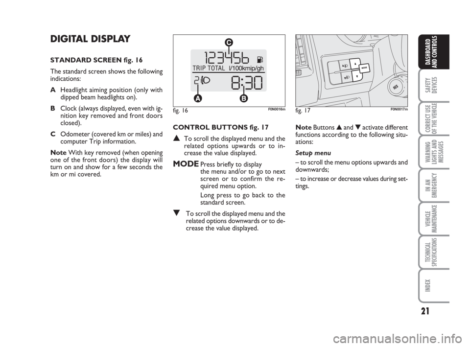
STANDARD SCREEN fig. 16
The standard screen shows the following
indications:
AHeadlight aiming position (only with
dipped beam headlights on).
BClock (always displayed, even with ig-
nition key removed and front doors
closed).
COdometer (covered km or miles) and
computer Trip information.
NoteWith key removed (when opening
one of the front doors) the display will
turn on and show for a few seconds the
km or mi covered.CONTROL BUTTONS fig. 17
▲To scroll the displayed menu and the
related options upwards or to in-
crease the value displayed.
MODEPress briefly to display
the menu and/or to go to next
screen or to confirm the re-
quired menu option.
Long press to go back to the
standard screen.
▼To scroll the displayed menu and the
related options downwards or to de-
crease the value displayed.NoteButtons ▲and ▼activate different
functions according to the following situ-
ations:
Setup menu
– to scroll the menu options upwards and
downwards;
– to increase or decrease values during set-
tings.
fig. 16F0N0016mfig. 17F0N0017m
Page 27 of 282
26
SAFETY
DEVICES
CORRECT USE
OF THE
VEHICLE
WARNING
LIGHTS AND
MESSAGES
IN AN
EMERGENCY
VEHICLE
MAINTENANCE
TECHNICAL
SPECIFICATIONS
INDEX
DASHBOARD
AND CONTROLS
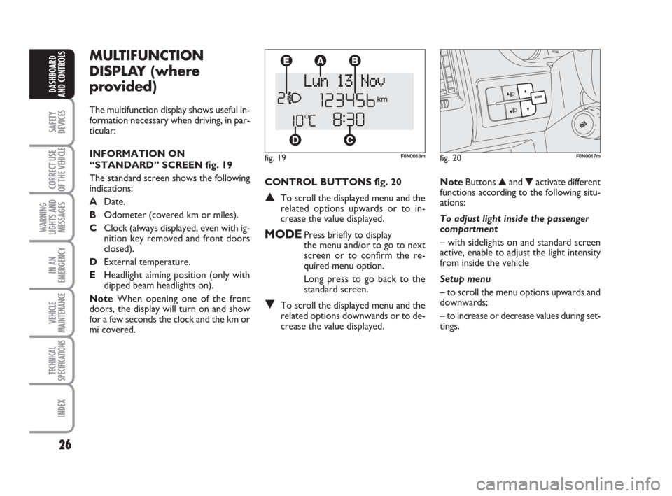
CONTROL BUTTONS fig. 20
▲To scroll the displayed menu and the
related options upwards or to in-
crease the value displayed.
MODEPress briefly to display
the menu and/or to go to next
screen or to confirm the re-
quired menu option.
Long press to go back to the
standard screen.
▼To scroll the displayed menu and the
related options downwards or to de-
crease the value displayed.
MULTIFUNCTION
DISPLAY (where
provided)
The multifunction display shows useful in-
formation necessary when driving, in par-
ticular:
INFORMATION ON
“STANDARD” SCREEN fig. 19
The standard screen shows the following
indications:
ADate.
BOdometer (covered km or miles).
CClock (always displayed, even with ig-
nition key removed and front doors
closed).
DExternal temperature.
EHeadlight aiming position (only with
dipped beam headlights on).
NoteWhen opening one of the front
doors, the display will turn on and show
for a few seconds the clock and the km or
mi covered.
fig. 19F0N0018m
NoteButtons ▲and ▼activate different
functions according to the following situ-
ations:
To adjust light inside the passenger
compartment
– with sidelights on and standard screen
active, enable to adjust the light intensity
from inside the vehicle
Setup menu
– to scroll the menu options upwards and
downwards;
– to increase or decrease values during set-
tings.
fig. 20F0N0017m
Page 77 of 282
76
SAFETY
DEVICES
CORRECT USE
OF THE
VEHICLE
WARNING
LIGHTS AND
MESSAGES
IN AN
EMERGENCY
VEHICLE
MAINTENANCE
TECHNICAL
SPECIFICATIONS
INDEX
DASHBOARD
AND CONTROLS
“FOLLOW ME HOME”
DEVICE
This function allows the illumination of the
space in front of the vehicle for a preset
period of time.
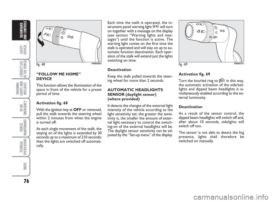
Activation fig. 68
With the ignition key at OFFor removed,
pull the stalk towards the steering wheel
within 2 minutes from when the engine
is turned off.
At each single movement of the stalk, the
staying on of the lights is extended by 30
seconds up to a maximum of 210 seconds;
then the lights are switched off automati-
cally. Each time the stalk is operated, the in-
strument panel warning light 3will turn
on together with a message on the display
(see section “Warning lights and mes-
sages”) until the function is active. The
warning light comes on the first time the
stalk is operated and will stay on up to au-
tomatic function deactivation. Each oper-
ation of the stalk will extend just the lights
switching on time.
Deactivation
Keep the stalk pulled towards the steer-
ing wheel for more than 2 seconds.
AUTOMATIC HEADLIGHTS
SENSOR (daylight sensor)
(where provided)
It detects the changes of the external light
intensity of the vehicle according to the
light sensitivity set: the greater the sensi-
tivity is, the smaller the amount of exter-
nal light necessary to control the switch-
ing-on of the external headlights will be.
The daylight sensor sensitivity can be ad-
justed by the “Set-up menu” of the display.Activation fig. 69
Turn the knurled ring to
2A:in this way,
the automatic activation of the side/tail-
lights and dipped beam headlights is si-
multaneously enabled according to the ex-
ternal luminosity.
Deactivation
As a result of the sensor control, the
dipped beam headlights will switch off and,
after about 10 seconds, sidelights will
switch off too.
The sensor is not able to detect the fog
presence, lights shall therefore be
switched on manually.
fig. 68F0N0036mfig. 69F0N0037m
Page 84 of 282
83
SAFETY
DEVICES
CORRECT USE
OF THE
VEHICLE
WARNING
LIGHTS AND
MESSAGES
IN AN
EMERGENCY
VEHICLE
MAINTENANCE
TECHNICAL
SPECIFICATIONS
INDEX
DASHBOARD
AND CONTROLS
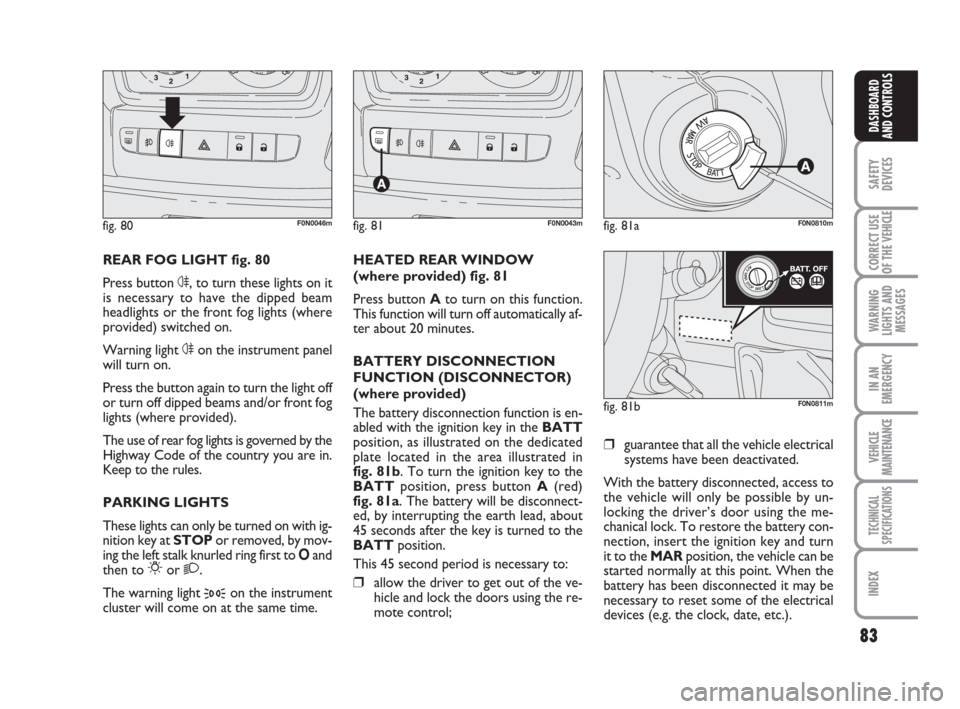
REAR FOG LIGHT fig. 80
Press button 4, to turn these lights on it
is necessary to have the dipped beam
headlights or the front fog lights (where
provided) switched on.
Warning light 4on the instrument panel
will turn on.
Press the button again to turn the light off
or turn off dipped beams and/or front fog
lights (where provided).
The use of rear fog lights is governed by the
Highway Code of the country you are in.
Keep to the rules.
PARKING LIGHTS
These lights can only be turned on with ig-
nition key at STOP or removed, by mov-
ing the left stalk knurled ring first to Oand
then to
6or 2.
The warning light
3on the instrument
cluster will come on at the same time.HEATED REAR WINDOW
(where provided) fig. 81
Press button Ato turn on this function.
This function will turn off automatically af-
ter about 20 minutes.
BATTERY DISCONNECTION
FUNCTION (DISCONNECTOR)
(where provided)
The battery disconnection function is en-
abled with the ignition key in the BATT
position, as illustrated on the dedicated
plate located in the area illustrated in
fig. 81b. To turn the ignition key to the
BATTposition, press button A(red)
fig. 81a. The battery will be disconnect-
ed, by interrupting the earth lead, about
45 seconds after the key is turned to the
BATTposition.
This 45 second period is necessary to:❒allow the driver to get out of the ve-
hicle and lock the doors using the re-
mote control;
fig. 80F0N0046mfig. 81F0N0043mfig. 81aF0N0810m
fig. 81bF0N0811m
❒guarantee that all the vehicle electrical
systems have been deactivated.
With the battery disconnected, access to
the vehicle will only be possible by un-
locking the driver’s door using the me-
chanical lock. To restore the battery con-
nection, insert the ignition key and turn
it to the MARposition, the vehicle can be
started normally at this point. When the
battery has been disconnected it may be
necessary to reset some of the electrical
devices (e.g. the clock, date, etc.).
Page 146 of 282
145
IN AN
EMERGENCY
VEHICLE
MAINTENANCE
TECHNICAL
SPECIFICATIONS
INDEX
DASHBOARD
AND CONTROLS
SAFETY
DEVICES
CORRECT USE
OF THE
VEHICLE
WARNING
LIGHTS AND
MESSAGES
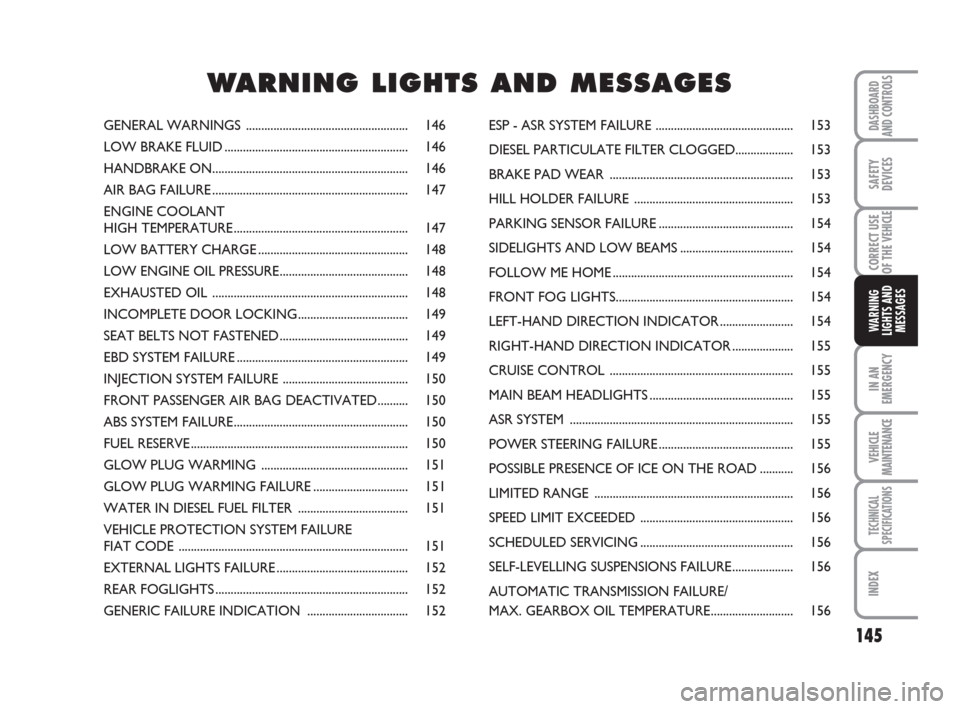
GENERAL WARNINGS ..................................................... 146
LOW BRAKE FLUID............................................................ 146
HANDBRAKE ON................................................................ 146
AIR BAG FAILURE................................................................ 147
ENGINE COOLANT
HIGH TEMPERATURE......................................................... 147
LOW BATTERY CHARGE................................................. 148
LOW ENGINE OIL PRESSURE.......................................... 148
EXHAUSTED OIL ................................................................ 148
INCOMPLETE DOOR LOCKING.................................... 149
SEAT BELTS NOT FASTENED.......................................... 149
EBD SYSTEM FAILURE........................................................ 149
INJECTION SYSTEM FAILURE ......................................... 150
FRONT PASSENGER AIR BAG DEACTIVATED.......... 150
ABS SYSTEM FAILURE......................................................... 150
FUEL RESERVE....................................................................... 150
GLOW PLUG WARMING ................................................ 151
GLOW PLUG WARMING FAILURE............................... 151
WATER IN DIESEL FUEL FILTER .................................... 151
VEHICLE PROTECTION SYSTEM FAILURE
FIAT CODE ........................................................................... 151
EXTERNAL LIGHTS FAILURE........................................... 152
REAR FOGLIGHTS............................................................... 152
GENERIC FAILURE INDICATION ................................. 152ESP - ASR SYSTEM FAILURE ............................................. 153
DIESEL PARTICULATE FILTER CLOGGED................... 153
BRAKE PAD WEAR ............................................................ 153
HILL HOLDER FAILURE .................................................... 153
PARKING SENSOR FAILURE............................................ 154
SIDELIGHTS AND LOW BEAMS..................................... 154
FOLLOW ME HOME........................................................... 154
FRONT FOG LIGHTS.......................................................... 154
LEFT-HAND DIRECTION INDICATOR........................ 154
RIGHT-HAND DIRECTION INDICATOR.................... 155
CRUISE CONTROL ............................................................ 155
MAIN BEAM HEADLIGHTS............................................... 155
ASR SYSTEM ......................................................................... 155
POWER STEERING FAILURE............................................ 155
POSSIBLE PRESENCE OF ICE ON THE ROAD ........... 156
LIMITED RANGE ................................................................. 156
SPEED LIMIT EXCEEDED .................................................. 156
SCHEDULED SERVICING.................................................. 156
SELF-LEVELLING SUSPENSIONS FAILURE.................... 156
AUTOMATIC TRANSMISSION FAILURE/
MAX. GEARBOX OIL TEMPERATURE........................... 156
WW W
A A
R R
N N
I I
N N
G G
L L
I I
G G
H H
T T
S S
A A
N N
D D
M M
E E
S S
S S
A A
G G
E E
S S
Page 155 of 282
154
IN AN
EMERGENCY
VEHICLE
MAINTENANCE
TECHNICAL
SPECIFICATIONS
INDEX
DASHBOARD
AND CONTROLS
SAFETY
DEVICES
CORRECT USE
OF THE
VEHICLE
WARNING
LIGHTS AND
MESSAGES
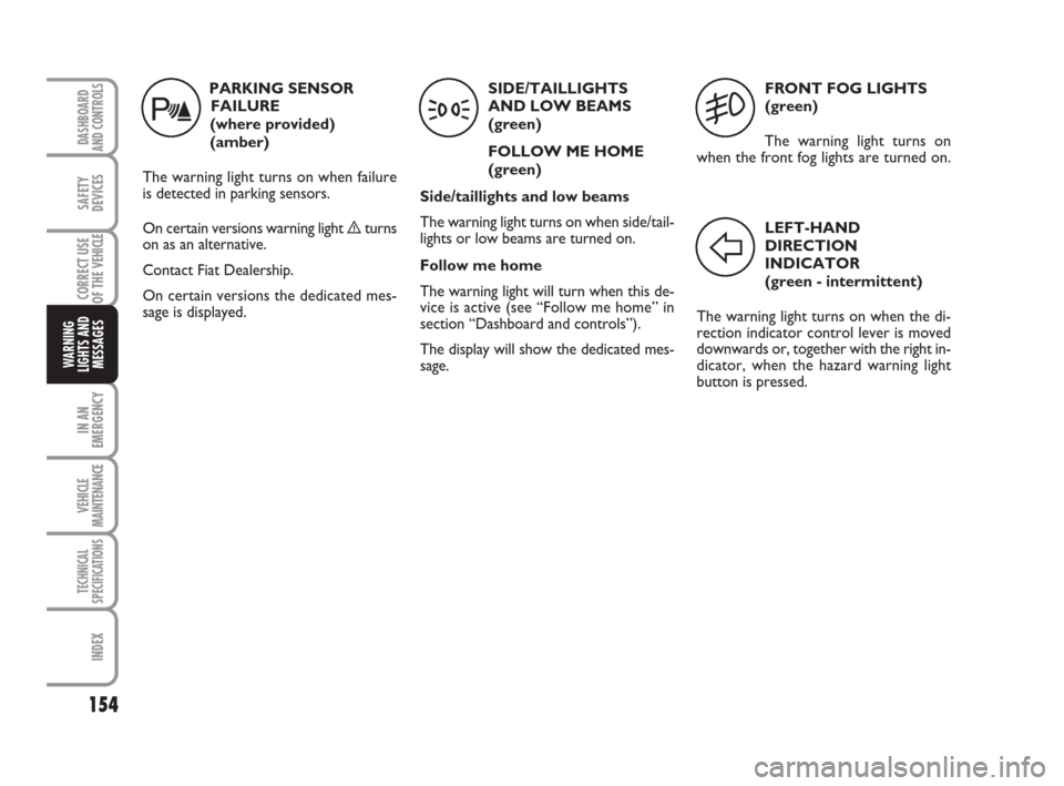
FRONT FOG LIGHTS
(green)
The warning light turns on
when the front fog lights are turned on.
5
LEFT-HAND
DIRECTION
INDICATOR
(green - intermittent)
The warning light turns on when the di-
rection indicator control lever is moved
downwards or, together with the right in-
dicator, when the hazard warning light
button is pressed.
F
PARKING SENSOR
FAILURE
(where provided)
(amber)
The warning light turns on when failure
is detected in parking sensors.
On certain versions warning light èturns
on as an alternative.
Contact Fiat Dealership.
On certain versions the dedicated mes-
sage is displayed.
t
SIDE/TAILLIGHTS
AND LOW BEAMS
(green)
FOLLOW ME HOME
(green)
Side/taillights and low beams
The warning light turns on when side/tail-
lights or low beams are turned on.
Follow me home
The warning light will turn when this de-
vice is active (see “Follow me home” in
section “Dashboard and controls”).
The display will show the dedicated mes-
sage.
3
Page 169 of 282
168
WARNING
LIGHTS AND
MESSAGES
VEHICLE
MAINTENANCE
TECHNICAL
SPECIFICATIONS
IINDEX
DASHBOARD
AND CONTROLS
SAFETY
DEVICES
CORRECT USE
OF THE
VEHICLE
IN AN
EMERGENCY
WHEN NEEDING TO
CHANGE A BULB
GENERAL INSTRUCTIONS
❒When a light is not working, check
that the corresponding fuse is intact
before changing a bulb. For the loca-
tion of fuses, refer to the paragraph “If
a fuse blows” in this section;
❒Before changing a bulb check the con-
tacts for oxidation;
❒Burnt bulbs must be replaced by oth-
ers of the same type and power;
❒Always check the height of the head-
light beam after changing a bulb.
IMPORTANT The headlight inner surface
may be lightly misted over: this is not a
fault but a natural fact due to low tem-
perature and the level of air humidity. It
will disappear as soon the headlights are
turned on. The presence of drops inside
the headlights means water infiltration,
therefore contact Fiat Dealership.
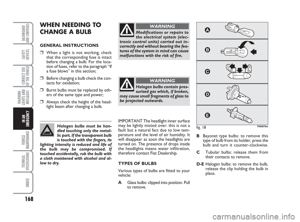
TYPES OF BULBS
Various types of bulbs are fitted to your
vehicle:
AGlass bulbs: clipped into position. Pull
to remove.BBayonet type bulbs: to remove this
type of bulb from its holder, press the
bulb and turn it counter-clockwise.
CTubular bulbs: release them from
their contacts to remove.
D-EHalogen bulbs: to remove the bulb,
release the clip holding the bulb in
place. Halogen bulbs must be han-
dled touching only the metal-
lic part. If the transparent bulb
is touched with the fingers, its
lighting intensity is reduced and life of
the bulb may be compromised. If
touched accidentally, rub the bulb with
a cloth moistened with alcohol and al-
low to dry.
Modifications or repairs to
the electrical system (elec-
tronic control units) carried out in-
correctly and without bearing the fea-
tures of the system in mind can cause
malfunctions with the risk of fire.
WARNING
Halogen bulbs contain pres-
surised gas which, if broken,
may cause small fragments of glass to
be projected outwards.
WARNING
fig. 18F0N0078m
Page 171 of 282
170
WARNING
LIGHTS AND
MESSAGES
VEHICLE
MAINTENANCE
TECHNICAL
SPECIFICATIONS
IINDEX
DASHBOARD
AND CONTROLS
SAFETY
DEVICES
CORRECT USE
OF THE
VEHICLE
IN AN
EMERGENCY
IF AN EXTERIOR LIGHT
BURNS OUT
For the type of bulb and power rating, see
“When needing to change a bulb”.
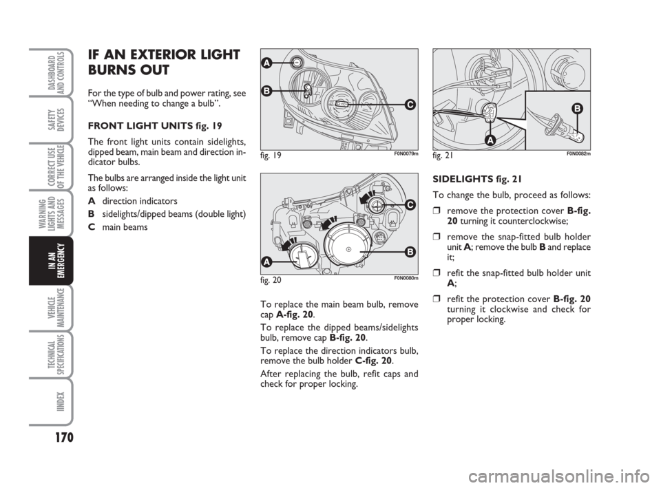
FRONT LIGHT UNITS fig. 19
The front light units contain sidelights,
dipped beam, main beam and direction in-
dicator bulbs.
The bulbs are arranged inside the light unit
as follows:
Adirection indicators
Bsidelights/dipped beams (double light)
Cmain beams
To replace the main beam bulb, remove
cap A-fig. 20.
To replace the dipped beams/sidelights
bulb, remove cap B-fig. 20.
To replace the direction indicators bulb,
remove the bulb holder C-fig. 20.
After replacing the bulb, refit caps and
check for proper locking.SIDELIGHTS fig. 21
To change the bulb, proceed as follows:
❒remove the protection cover B-fig.
20turning it counterclockwise;
❒remove the snap-fitted bulb holder
unit A; remove the bulb Band replace
it;
❒refit the snap-fitted bulb holder unit
A;
❒refit the protection cover B-fig. 20
turning it clockwise and check for
proper locking.
fig. 19F0N0079mfig. 21F0N0082m
fig. 20F0N0080m
Page 172 of 282
171
WARNING
LIGHTS AND
MESSAGES
VEHICLE
MAINTENANCE
TECHNICAL
SPECIFICATIONS
INDEX
DASHBOARD
AND CONTROLS
SAFETY
DEVICES
CORRECT USE
OF THE
VEHICLE
IN AN
EMERGENCY
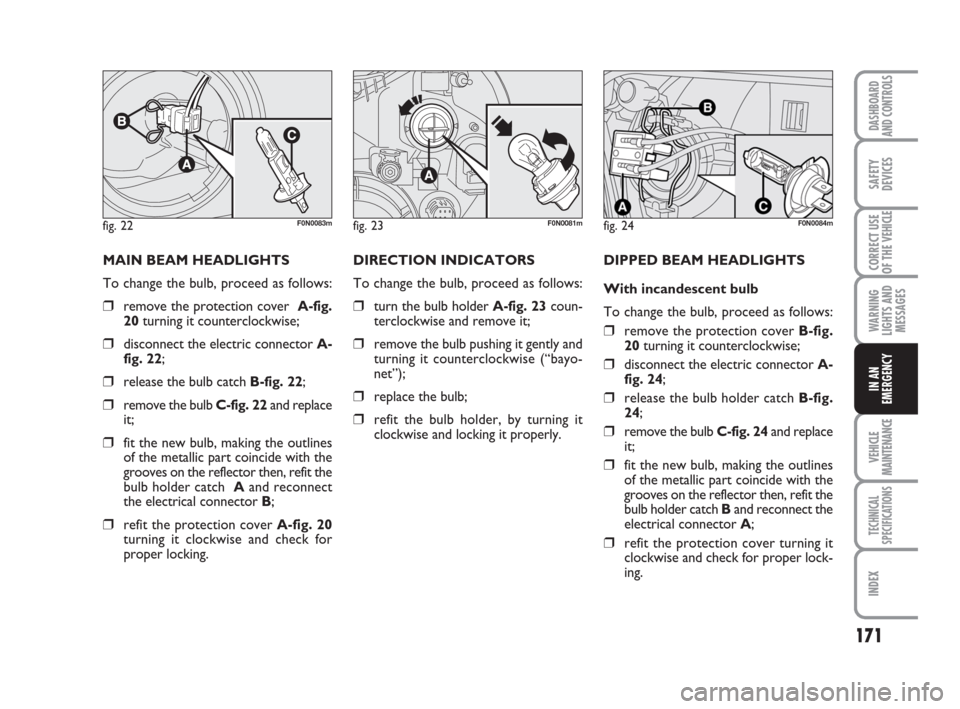
MAIN BEAM HEADLIGHTS
To change the bulb, proceed as follows:
❒remove the protection cover A-fig.
20 turning it counterclockwise;
❒disconnect the electric connector A-
fig. 22;
❒release the bulb catch B-fig. 22;
❒remove the bulb C-fig. 22 and replace
it;
❒fit the new bulb, making the outlines
of the metallic part coincide with the
grooves on the reflector then, refit the
bulb holder catch Aand reconnect
the electrical connector B;
❒refit the protection cover A-fig. 20
turning it clockwise and check for
proper locking.DIRECTION INDICATORS
To change the bulb, proceed as follows:
❒turn the bulb holder A-fig. 23coun-
terclockwise and remove it;
❒remove the bulb pushing it gently and
turning it counterclockwise (“bayo-
net”);
❒replace the bulb;
❒refit the bulb holder, by turning it
clockwise and locking it properly.DIPPED BEAM HEADLIGHTS
With incandescent bulb
To change the bulb, proceed as follows:
❒remove the protection cover B-fig.
20turning it counterclockwise;
❒disconnect the electric connector A-
fig. 24;
❒release the bulb holder catch B-fig.
24;
❒remove the bulb C-fig. 24and replace
it;
❒fit the new bulb, making the outlines
of the metallic part coincide with the
grooves on the reflector then, refit the
bulb holder catch Band reconnect the
electrical connector A;
❒refit the protection cover turning it
clockwise and check for proper lock-
ing.
fig. 22F0N0083mfig. 23F0N0081mfig. 24F0N0084m
Page 184 of 282
183
WARNING
LIGHTS AND
MESSAGES
VEHICLE
MAINTENANCE
TECHNICAL
SPECIFICATIONS
INDEX
DASHBOARD
AND CONTROLS
SAFETY
DEVICES
CORRECT USE
OF THE
VEHICLE
IN AN
EMERGENCY
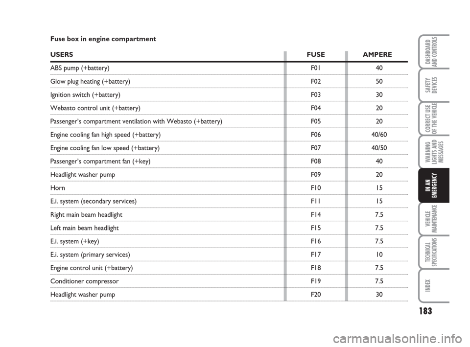
Fuse box in engine compartment
USERSFUSE AMPERE
ABS pump (+battery) F01 40
Glow plug heating (+battery) F02 50
Ignition switch (+battery) F03 30
Webasto control unit (+battery) F04 20
Passenger’s compartment ventilation with Webasto (+battery) F05 20
Engine cooling fan high speed (+battery) F06 40/60
Engine cooling fan low speed (+battery) F07 40/50
Passenger’s compartment fan (+key) F08 40
Headlight washer pump F09 20
HornF10 15
E.i. system (secondary services) F11 15
Right main beam headlight F14 7.5
Left main beam headlight F15 7.5
E.i. system (+key) F16 7.5
E.i. system (primary services) F17 10
Engine control unit (+battery) F18 7.5
Conditioner compressor F19 7.5
Headlight washer pump F20 30